
Dual Frequency GPS Antennas for Space Monitoring
Hocine Hamoudi
1,2
, Haddad Boualem
2
and Lognonne Phillipe
3
1
Institut National de la Poste et des TIC (INPTIC), EUCALYPTUS, Algiers, Algeria
2
Laboratoire de Traitement d'Image et Rayonnement (LTIR), FEI, USTHB, Algiers, Algeria
3
Institut de Physique du Globe de Paris, (IPGP), Paris, France
h_hamoudi@inptic.edu.dz, bhaddad_57@yahoo.fr, lognonne@ipgp.fr
Keywords: Antennas array, GNSS/GPS, Nanosatellite, patch antenna, TEC, tsunami alert.
Abstract: This work focuses on design and study of low cost corners truncated antennas arrays, printed on alumina,
operating at L1/L2 GPS frequencies. This device consists on one patch antennas array to be integrated, in a
warning system, with the aim of detecting ionosphere disturbances associated with land-based perturbations
and tsunami's arrivals at the coast. To address such concerns, we studied a dual frequency patch antennas
array. The performances of the antenna have been measured in terms of return loss, frequency of operation,
axial ratio, bandwidth, and radiation pattern. Particularity and major advantage of this antenna, compared to
conventional marketed GPS antennas, is the simultaneous use of both GPS frequencies L1 and L2.
1 INTRODUCTION
Natural disasters (volcanoes, tsunamis, floods ...) are
creating significant property damage and casualties.
Last decades, significant progress in detecting and
modelling the atmosphere disturbances induced by
climatic phenomena and seismic waves, were
performed. This research is now an important part of
the assignment and monitoring projects in the upper
atmosphere (Lognonné, Artru, Garcia, Crespon,
Ducic, Jeansou, Occhipinti, Helbert, Moreaux, and
Godet, 2006). In this framework, we are particularly
interested in the behavior of the ionosphere, which is
considered as the seat of physical phenomena.
Investigations of (Fenn, 2008) show that an antenna
array with adaptive directional beams is a promising
method to detect, using GPS /GNSS signals, some
disturbances in the ionosphere. For microstrip
antennas to be exploited in such systems, high
polarization purity and isolation between orthogonal
polarizations being linear or circular are needed.
Many shapes of the patch like rectangular patch,
elliptical patch, patch with loops, or Square ring
microstrip antenna with truncated corners (Chen, Wu,
and Wong, 1998) were used to obtain Circular
Polarization (CP). The circular polarization can be
obtained by well known method of a single-feed
square microstrip antenna with truncating a pair of
patch corners design. The main goal is the industrial
manufacturing of a GNSS/GPS network of smart
antennas. GNSS systems, however, offer other
perspectives, not initially intended to designing the
system, thanks to reflected GNSS signals. Therefore,
could we use the GNSS satellites as opportunity of
transmitters, and develop systems at ground surface,
airborne or embedded for imaging GNSS reflections
to deduce deformation of the Earth’s surface, or maps
of variation of sea level for tsunami survey and
monitoring ? Especially after the Sumatra’s tsunami
on 2004 and Fukushima on 2011. The development
of this new approach is the main objective of one of
the ‘Institut de Physique du Globe de Paris’
(IPGParis) project, which focused on demonstration
of the use of satellite navigation (GNSS) in existing
and new application areas, such as the Land and sea
monitoring. This is precisely the main objective of
this work which will go through system design, based
on GNSS antennas. The total size of the array is about
90 mm ×90 mm.
Compared to similar works in this area, the
proposed antenna array offers relatively small
dimensions, low weight, ease in fabrication, simple
structure, smaller number of layers and works at the
two GPS receiver frequencies, compared to
conventional existing GPS antennas which work at
L1 frequency only. The dual frequency antenna shall
be passive and requires no electrical power.
83
Hamoudi H., Boualem H. and Phillipe L.
Dual Frequency GPS Antennas for Space Monitoring.
DOI: 10.5220/0005421600830087
In Proceedings of the Third International Conference on Telecommunications and Remote Sensing (ICTRS 2014), pages 83-87
ISBN: 978-989-758-033-8
Copyright
c
2014 by SCITEPRESS – Science and Technology Publications, Lda. All rights reserved

In this paper, a 1× 4 dual frequency patch antenna
array, suitable for use in space monitoring with
Circular Polarization is presented.
2 CONTEXT & METHODOLOGY
GNSS which stands for Global Navigation Satellite
Systems, allow to measure positions in real time with
an accuracy ranging from a few meters to a few
centimetres. In terms of public used, GPS receiver
requires compact, low power lightweight, low cost,
high reliability and with mobility capability. In the
field of natural hazards, they are also used to measure
deformations, such as volcanoes or to monitor
changes in sea level in order to confirm a tsunami and
estimate its height in the open sea. The development
of a technique to detecting tsunami, thanks to the GPS
data, could therefore improve warning systems in the
seismogenic and tsunamigenic zones. The
information provided by this method is
complementary to those provided by classical
seismology. Hence, the proposed methodology is the
study of dual frequency antenna to be used in Global
Positioning System (GPS) receivers operating at Ll
(1575.42 MHz) and L2 (1227.6 MHz) frequency
bands.
3 SIMPLE ELEMENT ANTENNA
CONFIGURATION
Low profile, light weight, ease in fabrication, rugged,
conformal, and in some cases lower cost than
comparable antennas, are among favourable features
which help microstrip antenna to be used in a broad
range of modern applications. Microstrip antennas
have been designed and incorporated in very wide
range of systems, from commercial car navigation
GPS systems, biomedical systems, to sophisticated
satellite communication system.
The configuration of a single element of the array
is shown in Figure 1. To reduce the cost of antenna
manufacturing and making it more rigid, FR4
substrates are used, in a first time (Hamoudi, Haddad
and Lognonne, 2012) (Hamoudi Haddad and
Lognonne, 2013), but given constraining
specifications of the project such as satellite, it was
necessary to reduce the size of the device. For this
purpose, the miniaturization of the radiating element
using a substrate of acceptable cost and suitable for
space missions (mechanical properties, electrical and
thermal stresses) was our guideline. We also consider
the design of another antenna with dual frequency.
Our choice, for dielectric material, fell on alumina
(ε
r
=9.8 and h = 0.635 mm). To achieve a CP
operation, we have chosen a truncated corner antenna,
which consists of a squared patch with two opposites
corners cut in angle of 45°. After computation, using
equations (Sainati, 1996) and simulation we obtain:
a) A L2 antenna with the dimension of 38mm and
truncated length 2mm and b) L1 truncated square
patch with the dimension of 30 mm and truncated
length 4mm. The initial truncation length is kept
0.5mm, which is subsequently increased by 0.5mm in
each successive step while obtain satisfactory
performances.
We note that with a substrate constant about 9.8 it
was possible to reduce, significantly, the antenna size
from 43.1 mm and 57.4 mm (for epoxy glass) to 30
mm and 38 mm, so a reduction of approximately
35%. To verify the proposed design, a prototype of
the single element antennas with optimized
dimensions has been simulated. The simulation
results show the impedance bandwidth (VSWR < 2)
of 4% at L1 and 3.5% at L2 frequencies. For the
operating frequency, a peak antenna gain of 4.8 dB is
observed The simulated radiation patterns in two
principle planes at 1.57 GHz and 1.22 GHz are
satisfactory and suitable for our application.
With this configuration, we have shown that we
have two separate antennas for L1 and L2
frequencies, but we have not yet been able to optimize
the dimensions and size. The goal of this work is then
precisely the study of a two GPS frequencies that fit
to the same specifications previously mentioned for
receiving antennas
Figure 1: Simple element antenna geometry.
Dual frequency antennas consist of a single
radiating structure, which exhibits a resonant
behavior, both in terms of radiation and impedance
matching at two separate frequencies. In microstrip
antenna technology, dual frequency operation can be
achieved through several numbers of different
configurations. The basic three categories are
Third International Conference on Telecommunications and Remote Sensing
84

mentioned in (Sharma and Gupta, 1983). As
discussed in the cavity model, two different modes
can be excited on a single rectangular patch to obtain
dual frequency operation by adjusting the width and
the length of the patch according to the two separate
resonant frequencies. Orthogonal modes can be
excited either by using a single feed or by using two
separate feeds. The choice depends on the type of
application. When separate field configuration is
used, as long as the spacing between the feed points
is physically realizable, feeds must be positioned
close to the centre of the corresponding edges in order
to obtain good isolation levels between the ports.
Following this approach and based on the previous
results of two single patch antennas and using EM
simulator, we obtain a rectangular patch printed on
alumina with a length about 39 mm and width of 30
mm excited by two feed located at P1 (-0.75,+1) and
P2 (-0.75,+1).
By packaging this antenna configuration into a
compact patch type structure it will be suitable for use
on a 3U Nano-satellite for spatial missions. The
simple structure of microstrip antenna, previously,
was used to form two configurations of antennas with
2 patches and four patches. The compact
configurations of microstrips antennas dual-band
with 2 patches and 4 patches is shown on Fig. 2.
4 NTENNA ARRAY DESIGN
In the case of single patch element, it has been
observed that the antenna gain is quite low. That is
why we consider using an array of antennas in order
to increase the gain and improve the radiation
characteristics. The major advantage of antenna
arrays compared to a single antenna element is the
electronic scanning capability. To reduce the cost of
antenna fabrication and making it more rigid during
construction, FR4 substrates are used, in a first time
(Hamoudi et al., 2012) (Hamoudi et al., 2013), but
given specifications of the project such as satellite
geometry, volume and weight allocated to the
antenna, we were forced to reduce the size of the
device. To verify the proposed design, a prototype of
the single element antennas with optimized
dimensions has been simulated. We note that with a
substrate constant about 9.8 it was possible to reduce,
significantly, the antenna size from 43.1mm and 57.4
mm (for epoxy glass) to 30 mm and 38 mm, which
corresponds to a reduction of approximately 35%. A
single patch antenna can be used in a great majority
of applications; nevertheless, the gain of these
antennas is typically not sufficient to overcome path
loss. For this reason, we use an antenna array. The
gain of an array is typically many times larger than
the gain provided by a single radiating element.
Therefore, it is necessary to employ a number of
elements in an array combination to achieve the
required gain and pattern characteristics.
First, a two element array is simulated (1*2). The
most important points in the design of an antenna
array are the feed network and the element spacing
(d). In our case, we have opted for a parallel feed. The
parallel feed, also called the corporate feed, where the
patch elements are fed in parallel by the power
division transmission lines. The transmission line
divides into two branches and each branch divides
again until it reaches the patch elements. This is first
constructed by connecting two adjacent elements
together with a transmission line, calculated from (1)
and (3). Now, two separate groups need to be
connected together with a transmission line drawn
between the centre of the 4 mm wide transmission
line.
1
t
W
1
e
e
eff
0
0
1.444)]
t
W
0.667ln(
1.393
t
W
ε
η
Z
(1)
and, for
1
t
W
t
W
0.25
W
8t
ln
ε2π
η
Z
e
e
eff
0
0
(2)
Where
For
2π
1
t
W
)
h
4ππ
ln(1
t
h
π
1.25
t
W
t
W
e
(3)
For
2π
1
t
W
)
h
2π
ln(1
t
h
π
1.25
t
W
t
W
e
(4)
Figure 2: (1*2) and (1*4) element antennas geometry.
Dual Frequency Gps Antennas for Space Monitoring
85
1.00 1.10 1.20 1.30 1.40 1.50 1.60
Freq [GHz]
-50.00
-40.00
-30.00
-20.00
-10.00
0.00
dB(S(P1,P1))
HFSSDesign1
XY Plot 12
ANSOFT
Curve Info
dB(S(P1,P1))
Setup1 : Sweep1
1.00 1.10 1.20 1.30 1.40 1.50 1.60
Freq [GHz]
0.00
5.00
10.00
15.00
20.00
25.00
30.00
35.00
40.00
45.00
dB(VSWR(P1))
HFSSDesign1
XY Plot 13
ANSOFT
Curve Info
dB(VSWR(P1))
Setup1 : Sweep1
Where W
e
is the effective width of the patch, t is
the thickness of the dielectric substrate, and ε
eff
effective dielectric constant of the patch, Z
0
is the
impedance of the transmission line and η
0
is the free
space intrinsic impedance (120π). The transmission
line is split using T-junction with equal power split.
In general, the array elements should be as far as
possible from each other, so the mutual coupling
becomes negligible. In our case, the inter-element
distance at set and fixed at 25 mm. Once the
performance of the single antenna (2 patches)
established, we went further to the study and
simulation of the network (1*4) (four patches) in
terms of S
11
, VSWR, radiation pattern and gain. The
major characteristics of adaptation and radiation are
shown, in table 1
Table 1: Antennas array parameters.
Parameters
antenna array
Frequency
1575.42 MHz
1227.6 MHz
LxW
(90 x 90)mm
2
Truncated length
4 mm
2 mm
V.S.W.R
1.8 dB
0.3 dB
Return loss (S
11
)
-17 dB
-46 dB
Gain (G)
10 dB
Axial Ratio
Good (<3dB)
Bandwidth
3.5 %
4%
Polarization
RHCP
The civilian signals issued from GNSS satellites
are all right hand circularly polarized (RHCP). These
antennas are made of Right Hand Circular
Polarization. This property will be used for our
antenna. Recall that circularly polarized antenna
arrays are more often used in wireless communication
systems as they can be easily mounted on mobile
devices. They provide: (1) more focused radiation
beams for better weather penetration and (2) good
cross polarization rejection.
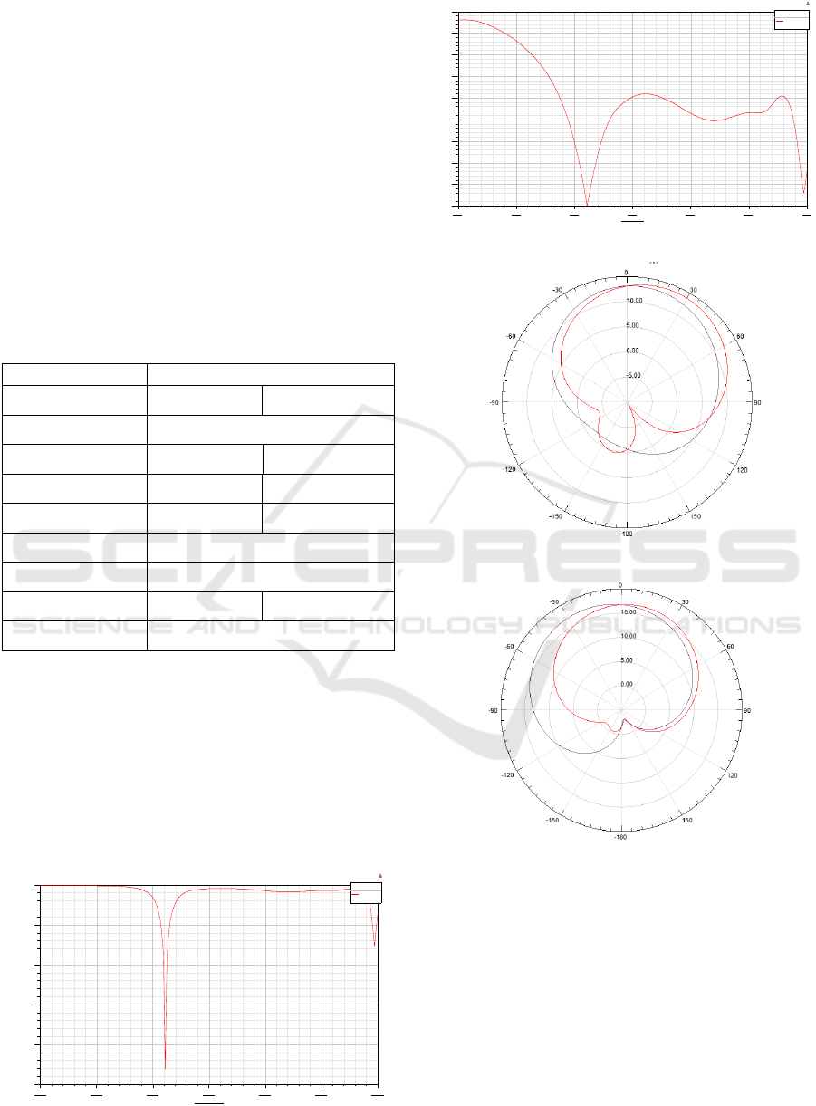
Figure 3: S
11
diagram for (1*4) antennas array.
Figure 4: V.S.W.R diagram for (1*4) antenna array.
Figure 5: Simulated E&H plane radiation pattern at L1.
Figure 6: Simulated E&H plane radiation pattern at L2.
A good agreement of the return loss value is
obtained at the operating frequencies, -17 dB and -46
dB, respectively, at L1 and L2. As can be seen in
comparison with single element and two elements
array, the return loss performance is increased. The
dual antenna VSWR is well below 2 at L1 and L2
frequency. Radiation patterns of all the proposed
antennas are derived using Electromagnetic
Simulator. The results at their resonating frequencies
are shown on Fig.5 and Fig.6. The antenna radiates to
the upper half-space, ideally to track visible satellite,
Third International Conference on Telecommunications and Remote Sensing
86

with a beamwidth at 3 dB of approximately 60º.
Moreover, we went from a gain of 4.8 dB for a
configuration with one patch to a gain of about 10 dB
with a configuration of 4 elements. The measured
performance of this antenna showed good agreement
with the specifications required to meet the
application needs.
5 CONCLUSION
A compact and low cost dual frequency array
antenna, operating at L1 and L2 is proposed. The
simulated characteristics of the proposed
configuration satisfy the requirements for GPS
application and spatial mission. The study of printed
antennas shows that, we were able to design an
antennas arrays consisting of four truncated square
elements, which will be used for tsunami warning
system and Total Electronic Content (TEC)
measurement.
As it is seen on Section 4, simulation results are
satisfactory for input reflection coefficient, VSWR,
radiation patterns, beam-width at 3 dB and axial ratio.
The present network thus proposed with acceptable
gain, ease in manufacturing, low cost, lightweight and
small footprint meets our goal. In comparison with
similar works in this area, the proposed antennas
array offers relatively small dimensions, simple
structure, low cost and the major advantage is
operation at both GPS L1 and L2 frequencies at the
same time. The antenna prototypes will, thereafter, be
related to a GPS OEM board and integrated to a
NanoSat "triple cube" designed for space monitoring.
As perspective to this work, we will consider the
study of a dual frequency network with 4 bi-
frequency elements.
REFERENCES
Chen W.S., Wu C.K., and Wong K.L. (1998). Single feed
squarering microstrip antenna with truncated corner
for compact circular polarization operation,
Electronics Letters (UK), vol. 34.
Fenn A.J. (2008), Adaptive Antennas and Phased Arrays
for Radar and Communications. Boston: Artech House.
Hamoudi H., Haddad B., and Lognonné P. (2012). Design
of an antenna array for GNSS/GPS network. In Image
and Signal Processing, A. Elmoataz et al. Eds.
ICISP2012. Lectures Notes in Computer Science
(7340), Springer, 183-190.
Hamoudi, H., Haddad B., and Lognonné P. (2013). Design
of an antenna array for GNSS/GPS network, IEEE, 7
th
EUCAP2013, Goteborg, Sweden, 2111-2115.
Lognonne P., Artru J., Garcia R., Crespon F., Ducic V.,
Jeansou E., Occhipinti G., Helbert J., Moreaux G., and
Godet P. (2006). Ground-based GPS imaging of
ionospheric post-seismic signal, Planetary and Space
Science, 54.
Sainati R.A. (1996). CAD of micro strip antenna for
wireless applications. Inc.: Artech House.
Sharma P.C., and Gupta K.C. (1983). Analysis and
optimised design of single point feed circularly
polarised microstrip antennas, IEEE Transaction on
Antenna Propagation (USA), vol. AP-31
Dual Frequency Gps Antennas for Space Monitoring
87
