
Architectural View Driven Model Transformations for
Supporting the Lifecycle of Parallel Applications
Ethem Arkin
1
and Bedir Tekinerdogan
2
1
Aselsan A.Ş., Ankara, Turkey
2
Information Technology Group, Wageningen University, Wageningen, Netherlands
Keywords: Parallel Computing, Architecture Modeling, Architecture Viewpoint, Model-to-Model Transformation.
Abstract: Two important trends can be identified in parallel computing. First of all, the scale of parallel computing
platforms is rapidly increasing. Secondly, the complexity and variety of current software systems requires to
consider the parallelization of application modules beyond algorithms. These two trends have led to a
complexity that is not scalable and tractable anymore for manual processing, and therefore automated support
is required to design and implement parallel applications. In this context, we present a model-driven
transformation chain for supporting the automation of the lifecycle of parallel computing applications. The
model-driven transformation chain adopts metamodels that are derived from architectural viewpoints. The
transformation chain is defined as a logical sequence consisting of model-to-model transformations. We
present the tool support that implements the metamodels and transformations.
1 INTRODUCTION
To increase the performance that is required from
large scale applications, the current trend is towards
applying parallel computing on multiple nodes. Here,
unlike serial computing in which instructions are
executed serially, multiple processing nodes are used
to execute the program instructions simultaneously.
To benefit from the parallel computing power,
usually parallel algorithms are defined that can be
executed simultaneously on multiple nodes. As such,
increasing the processing nodes will increase the
performance of the parallel programs. Different
studies have been carried out on the design and
analysis of parallel algorithms to support parallel
computing (Amdahl, 2007) (Frank, 2002) (Pllana and
Fahringer, 2002). These studies have provided useful
results and further increased the performance of
parallel computing. Several important challenges
have been identified and tackled in parallel
computing related to activities such as the analysis of
the parallel algorithm, the definition of the logical
configuration of the platform, and the mapping of the
algorithm to the logical configuration platform. The
research on parallel algorithms and its mapping to
parallel computing platforms is still ongoing.
We can identify two important trends in parallel
computing. First of all, the scale of parallel
computing platforms is rapidly increasing. Over the
last decade the number of processing nodes has
increased dramatically to tens and hundreds of thou-
sands of nodes providing processing performance
from petascale to exascale levels (Kogge et. al.,
2008). The second trend includes the increasing
complexity and variety of current software systems.
Here the design problem goes beyond the notion of
algorithms and data structures of the computation,
and the design of the overall system or application of
the parallel computing systems emerges as an
important problem. Hence, the challenge then
becomes not only analyzing, deploying and mapping
parallel algorithms but requires considering the
overall analysis and mapping of parallel applications
to parallel computing platform.
These two trends have led to a complexity that is
not scalable and tractable anymore for manual
processing, and therefore automated support is
required to design and implement parallel
applications. In this context, we present a model-
driven transformation chain for supporting the
automation of the lifecycle of parallel computing
applications. The model-driven transformation chain
adopts metamodels that are derived from architectural
viewpoints. The architecture viewpoints have been
defined in our earlier work for modeling the mapping
of parallel applications to parallel computing
platforms (Tekinerdogan and Arkin, 2013). In
essence, the viewpoints can be used to derive
40
Arkin E. and Tekinerdogan B..
Architectural View Driven Model Transformations for Supporting the Lifecycle of Parallel Applications.
DOI: 10.5220/0005231600400049
In Proceedings of the 3rd International Conference on Model-Driven Engineering and Software Development (MODELSWARD-2015), pages 40-49
ISBN: 978-989-758-083-3
Copyright
c
2015 SCITEPRESS (Science and Technology Publications, Lda.)

architectural views that serve as blueprints for
realizing the system. The viewpoints are in essence
visual and do not support the automated processing.
In this paper we map the viewpoints to domain
specific languages to represent architecture views as
textual executable descriptions that can be used in
model transformations to automate the steps of the
life cycle of parallel computing. The transformation
chain is defined as a logical sequence consisting of
model-to-model transformations. We present the tool
support that implements the metamodels and
transformations
The remainder of the paper is organized as
follows. In section 2, we shortly describe the
viewpoints which form the basis for the domain
specific languages and the model transformations.
Section 3 presents the model transformation approach
and the model transformations. Section 4 describes
the implementation and the toolset. Section 5 presents
the related work and finally we conclude the paper in
section 6.
2 PRELIMINARIES
In principle we can identify the following important
concerns in the life cycle for modeling parallel
applications:
Identifying Parallel and Serial Modules in the
Application
Depending on the application semantics, while some
modules can run in parallel others can only run in
serial. Typically serial modules will be mapped to a
single node, while parallel modules need to be
mapped to multiple nodes. For the architect it is
important to depict these explicitly and as such help
to identify the proper selection of parallel module.
Modeling of the Physical Computing Platform
The application will run on a selected or to be selected
physical configuration platform that consists of
multiple nodes. The architect needs to be able to
model the physical computing platform for smaller
but also for very large computing platforms (e.g.
exascale computing).
Mapping of Modules and Algorithms to Physical
Nodes
The mapping of the modules to the computing
platforms can be done in different ways. The mapping
can be usually done in many different alternative
ways and each alternative will typically behave
differently with respect to quality metrics such as
speedup and efficiency. The architecture needs to be
able to communicate the decision on which mapping
is made. Based on this the optimal design decision
can be made.
Defining the Interaction Patterns among Parallel
Modules
Parallel modules and algorithms will typically
exchange information to perform the requested tasks.
In general it is important to define the proper
interaction patterns not only for functional reasons
but also to optimize the parallelization overhead and
as such increase efficiency.
Modeling Multiple Computer Architectures
When considering application instead of
algorithm only it appears that we cannot reduce the
problem to one of the computing platforms as defined
in the Flynn’s taxonomy. Typically, multiple of these
categories are integrated in the overall application.
That is, for example, both the SIMD and MISD could
be needed for realizing the application. For complex
applications all the four kinds of computing
architectures might be required. The Order
Management case is such an example.
Based upon the number of concurrent instruction
(or control) and data streams available in the
architecture the so-called Flynn’s Taxonomy
distinguishes among the following types of
computing architectures (Flynn, 1972):
Single Instruction, Single Data (SISD): This
architecture exploits no parallelism in either the
datastream or instructions. A traditional
uniprocessor computer like the PC is an example
to this type of architecture.
Single Instruction, Multiple Data (SIMD): This
architecture exploits multiple data streams using a
single instruction stream to perform operations
that may be parallelized. For example, processor
arrays or GPUs process multiple pixel data on an
image using the same instruction set.
Multiple Instruction, Single Data (MISD): In this
architecture multiple instructions operate on a
single data stream. Pipeline architectures are often
considered as an example of this type.
Multiple Instruction, Multiple Data (MIMD): This
architecture exploits multiple processors
executing different instructions on different data
simultaneously. Distributed systems, clusters,
grid systems are examples of MIMD
architectures.
Based on the above concerns we have proposed an
architecture framework consisting of a coherent set of
viewpoints which addresses the different concerns for
supporting the design of parallel applications
(Tekinerdogan and Arkin, 2015). These six
viewpoints are as follows:
ArchitecturalViewDrivenModelTransformationsforSupportingtheLifecycleofParallelApplications
41
Application Decomposition Viewpoint
This viewpoint aims to support the analysis and
decomposition of the application into parallel and
serial modules. A module can be either a package that
is a grouping module element to group a set of
modules or a module that can be serial, parallel, serial
algorithm or parallel algorithm. A serial module and
a serial algorithm module is the implementation of a
set of instructions or algorithm which is executed on
a single processing unit. A parallel module is a
module with the instruction set that run on multiple
processing units simultaneously.
Algorithm Decomposition Viewpoint
Each module in the application decomposition
viewpoint has a separate behavior for the deployment
of the application. A serial module or a serial
algorithm module can be deployed and executed on a
single processing unit. A parallel module consists of
a set of instructions that will be executed among
different processing units simultaneously. A parallel
algorithm module includes serial or parallel sections
that determines the behavior of the algorithm and
must be decomposed into sections that will be
executed serial or parallel.
Component Viewpoint
According to the decomposition of the parallel
application, a component view includes serial
components, serial algorithm components, parallel
components and parallel algorithm components. The
types of the components are determined by the
module that is compiled to the component.
Physical Configuration Viewpoint
Physical configuration viewpoint includes the
hardware configuration for the parallel computing
platform including nodes, network, processing units,
memory and bus.
Deployment Viewpoint
Deployment viewpoint is used to represent the
deployment of components to the physical
configuration view.
Logical Configuration Viewpoint
This viewpoint is used to represent the logical
communication patterns and the dynamic behavior of
the algorithm. Logical configuration is generated
according to the tile and communication pattern
definitions which is described in our earlier study
(Tekinerdogan and Arkin, 2013).
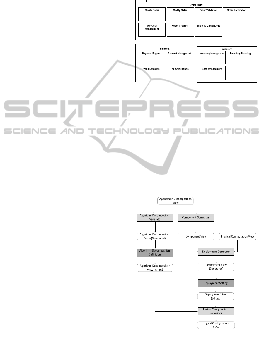
To illustrate the problem we will use the Order
Management Application architecture as an example.
The Order Management application is typically a
critical part of commercial systems including, for
example, packages like Order Entry, Financial and
Inventory. To increase the performance of such a
system several modules need to be run in parallel.
Figure 1: Order Management Application Architecture
(Decomposition View).
3 ARCHITECTURE VIEW
DRIVEN TRANSFORMATIONS
The architecture viewpoints of the previous section
can be used to realize the mapping of parallel
applications to parallel computing platforms.
However, the viewpoints are mainly visual and not
appropriate for automated support. In this section we
present the approach for automating the overall
process using the architecture viewpoints. Figure 2
represents the transformation chain including views
Figure 2: Transformation Chain for Supporting the
Lifecycle of Parallel Applications.
MODELSWARD2015-3rdInternationalConferenceonModel-DrivenEngineeringandSoftwareDevelopment
42
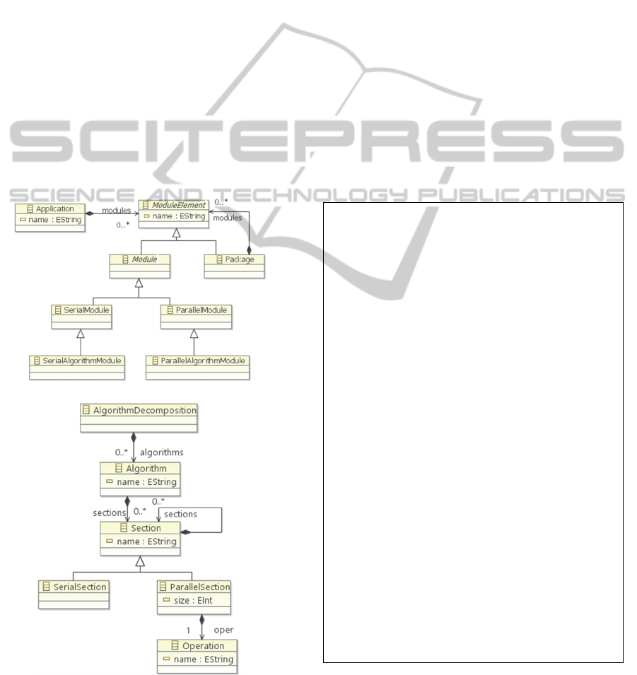
and transformations between the views for parallel
computing architectures. Four transformation
processes are defined including Algorithm
Decomposition Generator, Component Generator,
Deployment Generator, and Logical Configuration
Generator. In the following subsections we discuss
each generator in detail. In addition to the generators
the transformation chain include the two manual
activities Algorithm Decomposition Definition and
Deployment Setting. Both activities are used to
enhance additional details to the generated views. In
the activity Algorithm Decomposition Definition the
preliminary generated Algorithm Decomposition
View is manually edited for identifying the parallel
and serial sections of the algorithm (Arkin et. al.,
2013). In the activity Deployment Setting the parallel
components are manually assigned to physical
configuration processing units.
3.1 Algorithm Decomposition
Generator
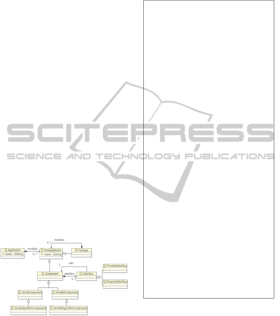
a) Application Decomposition Metamodel
b) Algorithm Decomposition Metamodel
Figure 3: Metamodels for Algorithm Decomposition
Generator.
Algorithm Decomposition Generator transforms the
ParallelAlgorithmModule elements of application
decomposition view to Algorithm elements of
algorithm decomposition view. Figure 3 shows the
metamodels of the application decomposition
viewpoint and algorithms decomposition viewpoint.
Application Decomposition metamodel (Figure 3a)
has a main Application element. Application includes
the Module Elements which can be either a Package
or a Module. Package contains other module
elements that can be either ParallelModule,
SerialModule, ParallelAlgorithmModule or
SerialAlgorithmModule. Algorithm Decomposition
metamodel (Figure 3b) contains parallel algorithms
used for the parallel application. Algorithm includes
Sections, Parallel Sections and Serial Sections. Each
section can contain other sections. A parallel
application is related to a parallel Operation that is
defined in the parallel library. This library is used for
defining reusable parallel operations using tiles and
communication patterns which are described in detail
in (Arkin et. al., 2013).
1. rule AlgorithmDecompositionGenerator
2. transform app :
3. applicationdecomposition!Application
4. to algs :
algorithmdecomposition!AlgorithmDecompositi
on
5. {
6. algs.algorithms = Sequence{};
7. for (module in app.modules)
8. {
9. generateAlgorithm(algs, module);
10. }
11. }
12. operation generateAlgorithm
13. (algs:
14. algorithmdecomposition!AlgorithmDecompositi
on,
15. module:
applicationdecomposition!ModuleElement)
16. {
17. if(module.isTypeOf(
18. applicationdecomposition!
19. ParallelAlgorithmModule))
20. {
21. var alg = new
22.
algorithmdecomposition!Algorithm;
23. alg.name = module.name;
24. algs.algorithms.add(alg);
25. }
26. if(module.isTypeOf(
27. applicationdecomposition!Package))
28. {
29. for (m in module.modules)
30. {
31. generateAlgorithm(algs, m);
32.
}
33. }
34. }
Figure 4: Algorithm Decomposition Generator
Transformation Rules.
ArchitecturalViewDrivenModelTransformationsforSupportingtheLifecycleofParallelApplications
43
The Algorithm Decomposition Generator searches
for the Parallel Algorithm Modules in the application
decomposition view and generates the algorithm
decomposition view. Figure 4 shows the
transformation rules of Algorithm Decompostion
Generator.
The main transformation rule iterates over the
modules of the application and calls the operation
generateAlgorithm for the module (lines 7-10). The
generateAlgorithm operation (lines 12-33) first
checks the module whether it is a
ParallelAlgorithmModule or a Package. If the
module is a Parallel Algorithm Module, then a new
algorithm instance is created and added to algorithm
list (lines 17-25). If the module is a Package, then
generateAlgorithm operation is recursively called for
each submodule (lines 26-32).
3.2 Component Generator
Component Generator transforms modules of
application decomposition view to components for
component view. The transformation uses
Application Decomposition Metamodel (Figure 3a)
and Component Metamodel (Figure 5). Component
metamodel includes Application element as main
element. Application consists of Packages and
Components. Similarly, components can be either
Parallel Component, Serial Component, Parallel
Algorithm Component or Serial Algorithm
Component. Each component has an Interface
relation with another component. A component has
required and provided interfaces.
Figure 5: Component Metamodel.
The transformation rules for Component
Generator is shown in Figure 6. The main
transformation rule is shown from lines 2 to 10. The
application decomposition view modules are
transformed into component view modules. The
transformModule operation is defined to implement
this transformation. The transformed module is added
1. rule ComponentGenerator
2. transform app :
applicationdecomposition!Application
3. to capp : component!Application {
4. capp.name = app.name;
5. capp.modules = Sequence{};
6. for (module in app.modules) {
7. capp.modules.add(
8. transformModule(module));
9. }
10. }
11. operation transformModule
12. (module:
13.
applicationdecomposition!ModuleElement
14. ) : component!ModuleElement {
15. var comp;
16. if(module.isTypeOf(
17.
applicationdecomposition!ParallelModule))
18. {
19. comp = new component!ParallelComponent;
20. comp.name = module.name;
21. }
22. if(module.isTypeOf(
23. applicationdecomposition!SerialModule))
24. {
25. comp = new component!SerialComponent;
26. comp.name = module.name;
27. }
28. if(module.isTypeOf(
29. applicationdecomposition!
30. ParallelAlgorithmModule))
31. {
32. comp = new
33.
component!ParallelAlgorithmComponent;
34. comp.name=module.name;
35. }
36. if(module.isTypeOf(
37. applicationdecomposition!
38. SerialAlgorithmModule))
39. {
40. comp = new
41. component!SerialAlgorithmComponent;
42. comp.name = module.name;
43. }
44. if(module.isTypeOf(
45. applicationdecomposition!Package))
46. {
47. comp = new component!Package;
48. comp.name = module.name;
49. comp.modules = Sequence{};
50. for (m in module.modules) {
51. comp.modules.add(transformModule(m));
52. }
53. }
54. return comp;
55. }
Figure 6: Component Generator Transformation Rules.
to component view in lines 7-8. In the
transformModule operation, the type of the
application decomposition module is checked. Each
module type is transformed to the counter component.
If the module is ParallelModule, then a new
ParallelComponent instance is created with the same
name (lines 16-21). If the module is SerialModule,
then a new SerialComponent instance is created (lines
22-27). In lines 28-35, ParallelAlgorithmComponent
is created from ParallelAlgorithmModule and in lines
MODELSWARD2015-3rdInternationalConferenceonModel-DrivenEngineeringandSoftwareDevelopment
44
36-43, SerialAlgorithmComponent is created from
SerialAlgorithmModule. If the module is a Package,
then the transformModule operation is called for its
submodules (lines 44-53).
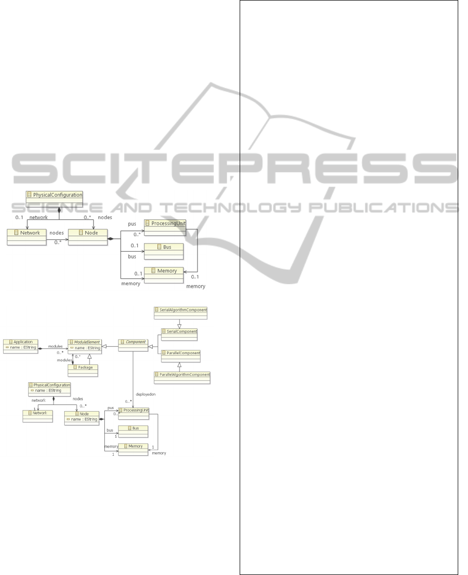
3.3 Deployment Generator
Deployment Generator merges and transforms the
component view and physical configuration view to
deployment view. The transformation uses the
Component Metamodel (Figure 5), Physical
Configuration Metamodel (Figure 7a) and
Deployment Metamodel (Figure 7b). The Physical
Configuration metamodel is adopted from
(Tekinerdogan and Arkin, 2013) which includes
Network, Node, Processing Unit, Bus and Memory
elements. Deployment metamodel is a composition of
component metamodel and physical configuration
metamodel which has a relation of <<deployed on>>
from component to processing unit.
a) Physical Configuration Metamodel
b) Deployment Metamodel
Figure 7: Metamodels for Deployment Generator.
The transformation rules as shown in Figure 8 have
two main rules. The first rule transforms the physical
configuration elements to deployment view elements.
The Physical Configuration Transform rule
transforms the physical configuration to deployment
configuration in which the network and nodes are
transformed to deployment instances. Each node of
the physical configuration is transformed to
deployment node calling transformNode operation in
line 8. The transformNode operation creates a new
node instance and transforms the memory, bus and
processing unit elements in the node (lines 12-19).
1. rule PhysicalConfigurationTransform
2. transform pc :
physicalconfiguration!PhysicalConfiguration
3. to dpc : deployment!PhysicalConfiguration
{
4. dpc.name = pc.name;
5. dpc.network = new deployment!Network;
6. dpc.nodes = Sequence{};
7. for (node in pc.nodes) {
8. dpc.nodes.add( transformNode(node)
);}
9. }
10. operation transformNode
11. (node: physicalconfiguration!Node) :
deployment!Node {
12. var n = new deployment!Node;
13. n.memory = new deployment!Memory;
14. n.bus = new deployment!Bus;
15. n.pus = Sequence{};
16. for (pu in node.pus) {
17. var p = new
deployment!ProcessingUnit;
18. p.memory = n.memory;
19. n.pus.add(p);}
20. return n;
21. }
22. rule ApplicationTransform
23. transform app : component!Application
24. to dapp : deployment!Application {
25. dapp.name = app.name;
26. dapp.modules = Sequence{};
27. for (module in app.modules) {
28.
dapp.modules.add(transformModule(module))
;}
29. }
30. operation transformModule
31. (module: component!ModuleElement) :
deployment!ModuleElement {
32.
var comp;
33. if(module.isTypeOf(component!ParallelComp
onent)) {
34. comp = new
deployment!ParallelComponent;
35. comp.name = module.name;}
36. if(module.isTypeOf(component!SerialCompon
ent)) {
37. comp = new
deployment!SerialComponent;
38. comp.name = module.name;}
39. if(module.isTypeOf(component!ParallelAlgo
rithmComponent)) {
40. comp = new
deployment!ParallelAlgorithmComponent;
41. comp.name = module.name;}
42. if(module.isTypeOf(component!SerialAlgori
thmComponent)) {
43. comp = new
deployment!SerialAlgorithmComponent;
44. comp.name = module.name;}
45. if(module.isTypeOf(component!Package)) {
46. comp = new deployment!Package;
47. comp.name = module.name;
48. comp.modules = Sequence{};
49. for (m in module.modules) {
50.
comp.modules.add(transformModule(m));}}
51. return comp;
52. }
Figure 8: Deployment Generator Transformation Rules.
ArchitecturalViewDrivenModelTransformationsforSupportingtheLifecycleofParallelApplications
45

The second rule transforms the component
application elements into deployment application
elements. Here, the modules of the component view
are transformed using transformModule operation
(lines 30-51), which checks the type of the module
and transforms to the counter element in the
deployment view.
3.4 Logical Configuration Generator
Logical Configuration Generator transforms an
algorithm decomposition view to a logical
configuration view using the information of the
deployment of parallel algorithm components to
processing units. The metamodel for logical
configuration is adopted and is used to generate the
dynamic behaviour of the algorithm using tiles,
communication patterns and operations. The
transformation rules to generate the logical
configuration is defined in Figure 9. The
transformation rules consist of three main parts. In the
first part, tiles that will be used according to
deployment view and algorithm sections are found
from the base library (lines 20-31). The prime
factorization method is used to find the tile size of
appropriate tiles. In the second part, patterns are
selected to generate the communication patterns for
the tiles with respect to the operations for the
algorithm sections (lines 32-44). Subsequently, these
selected patterns are added to the patterns list of the
corresponding operation. Later on when it is needed
the pattern can be reused in the last section in which
the final logical configuration is generated (lines 45-
54).
4 IMPLEMENTATION AND
TOOLSET
To assist the architect for applying the architecture
views and transforming using the transformation
chain, we have developed the toolset that implements
each architecture viewpoint metamodel and defined
transformation rules. For this we have used the
Epsilon (2014) toolset for Eclipse IDE that is used to
represent the notation (concrete syntax) of the
viewpoints. For each viewpoint we have defined the
corresponding metamodel. The metamodels are
defined in the Eclipse Modeling Framework (EMF)
using Emfatic language in Epsilon.
Figure 10 shows the architecture views for the
earlier defined case study, which are generated by the
transformation chain in the toolset. In
Figure 10a a test
1. operation library!Pattern
isDominating(tile:library!Core) : Boolean
2. operation logicalconfiguration!Pattern
getTile
3. (i:Integer, j:Integer) :
logicalconfiguration!Tile
4. operation logicalconfiguration!Pattern
setCommunication
5. (from_i:Integer, from_j:Integer,
to_i:Integer, to_j:Integer,
6. patternList:Sequence, level:Integer)
7. operation logicalconfiguration!Pattern
setCommunication
8. (ft:logicalconfiguration!Tile,
tt:logicalconfiguration!Tile)
9. operation createPattern
10. (main:logicalconfiguration!Pattern,
i:Integer, j:Integer,
11. patternList:Sequence,
commLevel:Integer, level:Integer,
12. parentSize:Integer, scaling:Any)
13.
14. rule LogicalConfigurationGenerator
15. merge base : library!AssetBase
16. with algorithm : algorithm!Algorithm
17. into lc :
logicalconfiguration!LogicalConfiguration {
18. for(parallelSection in
19. algorithm!ParallelSection.all) {
20. //FIND TILES
21. var n = coreSize;
22. while (i<=n) {
23. while ((n - (n/i * i)) = 0) {
24. factors.add(i);
25. n = n / i;}
26. i = i + 1;}
27. var
operationName=parallelSection.oper.name;
28. var sizeList = Sequence{};
29. i = 0;
30.
while(i < factors.size()){
31. sizeList.add(factors.get(i)); i = i +
1;}
32. //FIND PATTERNS
33. var patternList = Sequence{};
34. for(factor in sizeList){
35. for(oper in base.operations) {
36. if(oper.name == operationName) {
37. for(pattern in oper.uses) {
38. if(pattern.size == factor) {
39. //pattern.name.println();
40. //commLevel.println();
41. patternList.add(pattern);}}}}}
42. var commLevel = 0;
43. if(scaling == base!ScalingType#UP) {
44. commLevel = patternList.size - 1; }
45. //GENERATE LOGICAL CONFIGURATION
46. for(pattern in patternList) {
47. var mainPattern = new
48.
logicalconfiguration!Pattern;
49. createPattern(mainPattern, 0, 0,
patternList,
50. commLevel, 0, 1,
pattern.scaling);
51. var patternOperation = new
52.
logicalconfiguration!Operation;
53. mainPattern.implements =
patternOperation;}
54. lc.tiles.add(sectionPattern);}}
Figure 9: Logical Configuration Generator Transformation
Rules.
MODELSWARD2015-3rdInternationalConferenceonModel-DrivenEngineeringandSoftwareDevelopment
46
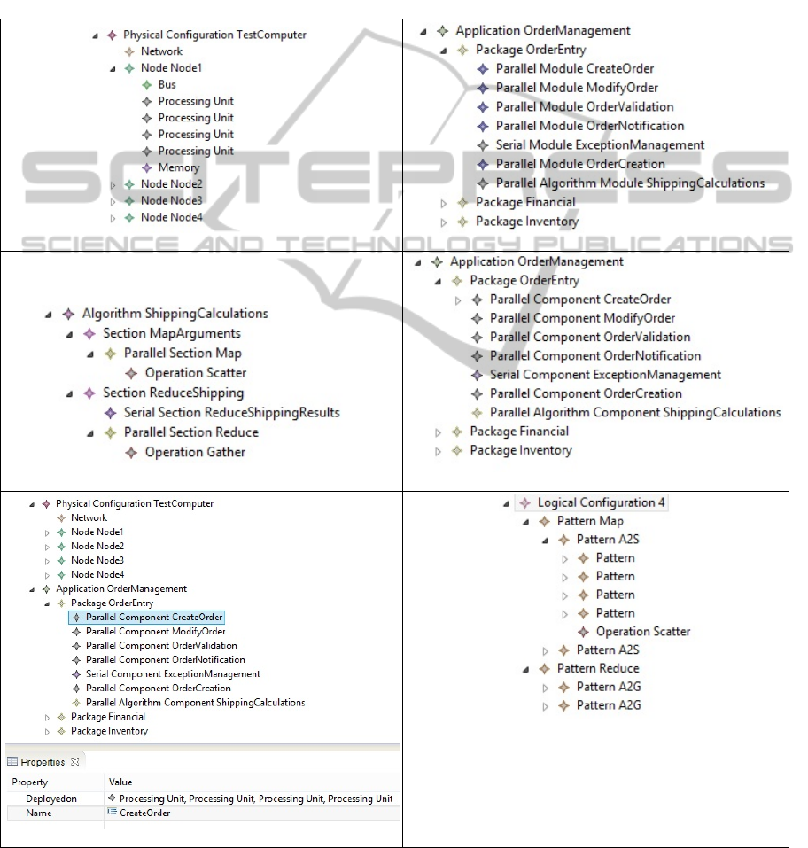
computer is defined with four nodes and a network
among nodes. Each node has four processing units, a
bus and a memory. Application decomposition for
Order Management Application, which is shown in
Figure 10b, is composed of three packages and each
package includes modules. In
Figure 10c, Algorithm
Decomposition View is generated using application
decomposition viewpoint, where parallel algorithm
module ShippingCalculations is defined. Component
viewpoint (
Figure 10d) is generated using application
decomposition. Deployment view (
Figure 10e)
includes test computer definition (physical
configuration), order management components and
<<deployedon>> relation property for each
component. Logical configuration (
Figure 10f) is
generated from algorithm decomposition using
parallel mapping library and the information that the
parallel algorithm component is deployed on which
processing units.
a) Physical Configuration View
b) Application Decomposition View
c) Algorithm Decomposition View d) Component View
e) Deployment View
f) Logical Configuration View
Figure 10: Architecture views generated by transformation chain.
ArchitecturalViewDrivenModelTransformationsforSupportingtheLifecycleofParallelApplications
47
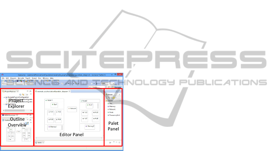
Moreover, in the toolset we have implemented
view editors for the architecture view definitions. The
Eclipse Graphical Modeling Framework (GMF)
models are generated from the EMF models using
EuGENia tool in Epsilon.
Figure 11
shows a snapshot of the toolset with the
example for Physical Configuration Editor. The user
interface of the editor provides four panels: 1) Project
Explorer, 2) Outline Overview, 3) Editor Panel and
4) Palet Panel. Project Explorer shows the projects
to define different physical configuration models.
Outline Overview shows the outline of the editing
physical configuration. Editor Panel, provides the
panel for editing the physical configuration using the
Viewpoint structures which can be selected and easily
added to the model by drag and drop. Finally, the
Palet Panel includes the view structures. In the
example a physical configuration with two nodes and
a network is given. Each node has 4 processing units
and a memory with a bus.
Figure 11: Physical Configuration Editor.
5 RELATED WORK
In the literature of parallel computing the particular
focus seems to have been on parallel programming
models such as MPI, OpenMP, CILK etc. (Talia,
2001) but the design and the modeling got less
attention. Several papers have focused in particular
on higher level design abstractions in parallel
computing and the adoption of model-driven
development.
Palyart et. al. (2012) propose an approach for
using model-driven engineering in high performance
computing. They focus on automated support for the
design of a high performance computing application
based on abstract platform independent model. The
approach includes the steps for successive model
transformations that enrich progressively the model
with platform information. The approach is supported
by a tool called Archi-MDE. Gamatie et al. (2011)
represent the Graphical Array Specification for
Parallel and Distributed Computing (GASPARD)
framework for massively parallel embedded systems
to support the optimization of the usage of hardware
resources. GASPARD uses MARTE standard profile
for modeling embedded systems at a high abstraction
level. MARTE models are then refined and used to
automatically generate code. Our approach can be
considered an alternative approach to both
GASPARD and Archi-MDE. The difference of our
approach is the particular focus on optimization at the
design level using architecture viewpoints.
In our earlier study (Arkin et. al., 2013)
(Tekinerdogan and Arkin, 2013), we have proposed
an architecture framework for mapping parallel
algorithms to parallel computing platforms. In that
study we only focused on parallel algorithms and did
not consider the broader concept of application. Also
we assumed a distributed memory model in which
each node has its own memory unit and, as such,
targeted the MISD architecture of the Flynn’s
taxonomy. The current approach is more general and
detailed in the sense that it focuses on software
application, supports both modules and algorithms,
can represent different memory models, supports
modeling different computing architectures, and most
importantly, supports the generation of the views.
6 CONCLUSIONS
We have applied model-driven transformation
techniques to support the automation of the mapping
of parallel applications to parallel computing
platforms. We have mainly focused on the practical
aspects and showed that this is indeed possible. We
could define the domain specific languages without
substantial problems and use these in the generators
that we implemented. The overall approach provides
a substantial support for the scalability problem in
parallel computing and increases the productivity and
quality. In our future work we will focus on
supporting design aspects beyond modeling, and
focus on optimizing the deployment configurations of
parallel applications.
REFERENCES
Amdahl, G.M., 2007. Validity of the Single Processor
Approach to Achieving Large Scale Computing
Capabilities, Reprinted from the AFIPS Conference
Proceedings, Vol. 30 (Atlantic City, N.J., Apr. 18–20),
MODELSWARD2015-3rdInternationalConferenceonModel-DrivenEngineeringandSoftwareDevelopment
48

AFIPS Press, Reston, Va., 1967, pp. 483–485, Solid-
State Circuits Newsletter, IEEE, vol.12, no.3, pp.19,20,
Summer.
Arkin, E., Tekinerdogan, B., Imre. K., 2013. Model-Driven
Approach for Supporting the Mapping of Parallel
Algorithms to Parallel Computing Platforms. Proc. of
the ACM/IEEE 16th International Conference on
Model Driven Engineering Languages and System.
Epsilon, http://www.eclipse.org/epsilon.
Flynn, M., 1972. Some Computer Organizations and Their
Effectiveness, Computers, IEEE Transactions on,
vol.C-21, no.9, pp.948, 960.
Frank, M.P., 2002. The physical limits of computing,
Computing in Science & Engineering, vol.4, no.3,
pp.16, 26, May-June.
Gamatié, A., Le Beux, S., Piel, E., Ben Atitallah, R., Etien,
R., Marquet, P., Dekeyser, J., 2011. A Model-Driven
Design Framework for Massively Parallel Embedded
Systems. ACM Transactions on Embedded Computing
Systems, 10(4), 1–36.
Kogge, P., Bergman, K., Borkar, S., Campbell, D., Carlson,
W., Dally, W., Denneau, M., Franzon, P., Harrod, W.,
Hiller, J., Karp, S., Keckler, S., Klein, D., Lucas, R.,
Richards, M., Scarpelli, A., Scott, S., Snavely, A.,
Sterling, T., Williams, R.S., Yelick, K., Bergman, K.,
Borkar, S., Campbell, D., Carlson, W., Dally, W.,
Denneau, M., Franzon, P., Harrod, W., Hiller, J.,
Keckler, S., Klein, D., Williams, R.S., and Yelick, K.,
2008. Exascale Computing Study: Technology
Challenges in Achieving Exascale Systems. DARPA.
Palyart, M., Ober, I., Lugato, D., Bruel, J., 2012. HPCML:
a modeling language dedicated to high-performance
scientific computing. In Proceedings of the 1st
International Workshop on Model-Driven Engineering
for High Performance and CLoud computing
(MDHPCL '12). ACM, New York, NY, USA, Article
6, 6 pages.
Pllana, S., Fahringer, T., 2002. UML based modeling of
performance oriented parallel and distributed
applications, Simulation Conference, 2002.
Proceedings of the Winter, vol.1, no., pp.497, 505 vol.1,
8-11.
Talia, D., 2001. Models and Trends in Parallel
Programming. Parallel Algorithms and Applications
16, no. 2: 145-180.
Tekinerdogan, B., Arkin. E., 2015. Architecture
Framework for Modeling the Deployment of Parallel
Applications on Parallel Computing Platforms, 3rd Int.
Conf. on Model-Driven Engineering and Software
Development (MODELSWARD 2015).
Tekinerdogan, B., Arkin, E., 2013. Architecture
Framework for Mapping Parallel Algorithms to Parallel
Computing Platforms, In MDHPCL@ MoDELS, pp.
53-62.
ArchitecturalViewDrivenModelTransformationsforSupportingtheLifecycleofParallelApplications
49
