
Modeling and Verification of B-based Distributed Reconfigurable
Control Systems
Raja Oueslati
1
, Olfa Mosbahi
2
Mohamed Khalgui
2
and Samir Ben Ahmed
1
1
Faculty of Sciences of Tunis, University of Tunis El Manar, Tunis, Tunisia
2
LISI, INSAT, University of Carthage, Carthage, Tunisia
Keywords:
Distributed Reconfigurable Control Systems, B Method, Modeling, Formal Verification, Multi-agent Archi-
tecture, Coordination.
Abstract:
The paper deals with the modeling and verification of B based Distributed Reconfigurable Control Systems
(DRCS). A distributed multi-agent architecture is developed, where for each system is affected a Reconfigu-
ration Agent to apply a local automatic reconfiguration, and a Coordination Agent is proposed to harmonize
between systems when any local reconfiguration is applied in a system. We apply the Distributed Reconfig-
urable B “DR-B” formalism to define all possible behaviors, to determine reconfiguration functions for each
system and to execute the appropriate ones to respond to reconfiguration requests and to switch between the
specific distributed configuration at run-time to cope with the coherence of running systems. We verify a
DRCS by using the B method. The goal is to guarantee the consistency and the correctness of the abstract
specification level. Further more, to avoid combinatorial explosion problem in DRCS, we apply the “Check R-
B” tool, to reduce redundant checking of different behaviors sharing similar operations. All the contributions
of this work are applied to two benchmark production systems FESTO and EnAS.
1 INTRODUCTION
Nowadays in industry, the development of safe dis-
tributed control systems is not a trivial activity be-
cause a failure can be critical for the safety of hu-
man being e.g. air and railway traffic control (khalgui
et al., 2012). In this context, one of the mostimportant
challenges is the trade-off between performance and
rapid response to market changes and customer needs.
One of the most promising directions, where consid-
erable progress has been made, to address these issues
is the reconfiguration of Distributed Control Systems
(DCS). We distinguish two types of reconfigurations:
static (offline) and dynamic (online) (Angelov et al.,
2005). The former is applied offline before system
cold starts, whereas the latter is applied automatically
at run-time. In the latter case, two types exist : man-
ual reconfigurations to be executed by users and au-
tomatic (intelligent) reconfigurations to be performed
by intelligent agents that can be a physical resource
(robot, machine ...) or a logical resource (scheduler),
and hybrid reconfigurations which are the combina-
tion of manual and automatic reconfigurations.
To deal with the automatic reconfiguration of dis-
tributed industrial control systems following the B
method, we propose, in this work a new distributed
multi-agent architecture. We define two kinds of
agents: Reconfiguration Agent (RA) which is as-
signed to each system to apply a local automatic re-
configuration and a Coordination Agent (CA) which
handles the coherence of distributed concurrent re-
configurations of different systems. A “DR-B” for-
malism is applied to model distributed reconfigurable
control systems. It consists of three modules: Behav-
ior, Control and Coordinator. The first defines all pos-
sible behaviors of the system, whereas the second is
a set of reconfiguration functions applied to change
each system from one configuration to another one at
run-time by adding or removing some operations in B
machines and the third module coordinates between
the different systems when applying a reconfiguration
scenario by executing the appropriate reconfiguration
functions. This reconfiguration scenario is applied as
a response to improve the system
′
s performance, or
also to recover and prevent hardware/software errors,
or also to adapt its behavior to new requirements ac-
cording to the environment evolution. After the mod-
eling of the DRCS, the next step is to check the cor-
rectness of the DRCS using B method. In order to
avoid combinatorial explosion problem, we apply the
“Check R-B” tool that was implemented, in (Oues-
lati et al., 2014), to reduce redundant checking of dif-
ferent behaviors sharing similar operations. To our
knowledge, this is the first contribution dealing with
124
Oueslati R., Mosbahi O., Khalgui M. and Ben Ahmed S..
Modeling and Verification of B-based Distributed Reconfigurable Control Systems.
DOI: 10.5220/0005244601240131
In Proceedings of the 5th International Conference on Pervasive and Embedded Computing and Communication Systems (PECCS-2015), pages
124-131
ISBN: 978-989-758-084-0
Copyright
c
2015 SCITEPRESS (Science and Technology Publications, Lda.)

the B method to dynamically and automatically re-
configure distributed industrial control systems.
The rest of the paper is organized as follows: in
the second Section, we present the background in
which we introduce B method. In the third Section,
we describe the two benchmark production systems
FESTO and EnAS to be followed in the paper as run-
ning examples to explain our contribution. We define,
in the next Section, the Distributed Reconfigurable
B “DR-B” formalism that we apply to our system.
The distributed multi-agent architecture is proposed,
in the fifth Section. In the sixth Section, we present
the “Check R-B” tool for DRCS. We finish by a con-
clusion and the exposition of our future works.
2 BACKGROUND KNOWLEDGE
We present in this section, the well-known B method.
2.1 Presentation of B
B is a formal method developed by Abrial to support
the software development life cycle from specifica-
tion to implementation (Abrial, 1996). It is based on
Zermelo-Fraenkel set theory and on generalized sub-
stitution. Sets are used for data modeling, General-
ized Substitutions are used to describe state modifi-
cation, and the refinement calculus is used to relate
models at varying abstraction levels. A machine B is
composed of header part allowing the identification
of the abstract machine, static part defining observa-
tions (sets, variables, constants, etc) of the system and
their invariant properties and dynamic part describing
operations changing the state of the system.
2.2 Composition in B
Abstract machines can be combined, through the
clauses INCLUDES, SEES, IMPORTS and USES to
build new specifications (Abrial, 1996). We are inter-
ested to the clause INCLUDES which allows a ma-
chine to be included in another one with read/write
access to the variables of the included machine. A
machine M includes a machine M1 means that M has
a full access to the constants, sets, variables and oper-
ations of M1 and operations of M can be defined by
using any M1 operations. It is worth mentioning that
at most one operation of the included machine can be
called from within an operation of the including ma-
chine. In order to avoid an obvious clash, we have
the possibility to rename a machine while including
it. This is done simply by prefixing, in the clause IN-
CLUDES, the name of the machine we want to re-
name with a certain identifier by a dot (x.M1, y.M1)
as explained in Figure 1.
Machine M(x,n)
............................
INCLUDES
x.M1, y.M1
OPERATIONS
C= PRE condition THEN x.A|| y.B END
END
Machine M1
............................
............................
............................
OPERATIONS
A= PRE ................THEN .........END
B= PRE ................THEN .........END
END
Figure 1: Clause INCLUDES.
3 CASES STUDIES: FESTO AND
EnAS
Two benchmark production systems FESTO and
EnAS (ref, ) are used as intact running examples in
this paper, in order to highlight the contributions of
our work. They are well documented laboratory sys-
tems used by many universities for research and edu-
cation purposes.
3.1 FESTO System
It consists of three units: Distribution Unit, Test Unit,
Processing Unit. The Distribution Unit is formed
of a pneumatic feeder and a converter which trans-
mits cylindrical workpieces from a stock to the Test
Unit. The Test Unit is composed of a detector, a tester
and an elevator. It performs tests on workpieces for
height, type of material and color. Workpieces that
satisfy these tests are transmitted to the Processing
Unit which is composed of a rotating disk, a drill
machine and a control machine. The rotating disk is
composed of locations to contain and transport work-
pieces from the input position, to the drilling position,
to the control position and finally to the output posi-
tion. Four production modes are assumed in this pa-
per to be applied in FESTO, depending on the number
of workpieces NP, as follows:
• Light1: If NP < C1, Then only Drill1 is used for
drilling workpieces.
• Light2: If NP < C1, Then only Drill2 is used for
drilling workpieces.
• Medium: If C1 ≤ NP < C2, Then Drill1 or Drill2
are used for drilling workpieces.
• High: If NP ≥ C2, Then the two drilling machines
are used simultaneously to drill two pieces at the
same time.
If both Drill1 and Drill2 are broken, the system is
completely stopped. We should make FESTO able
to switch production modes automatically at run-time
ModelingandVerificationofB-basedDistributedReconfigurableControlSystems
125
Light1
Light2
Medium
High
Drill1 error
or
user
Drill2 error
or
user
user
Drill1 error
Drill2 error
or
user
Drill1 error
or
user
user
user
user
Figure 2: Allowed reconfigurations of FESTO.
according to any changes in the working environment
caused by errors or user requirements without a halt.
It is assumed that the production modes are inter-
changeable as shown in Figure 2.
3.2 EnAS System
EnAS transports workpieces from FESTO into stor-
ing stations. The workpieces shall be placed inside
tins to close with caps afterwards. The EnAS sys-
tem is mainly composed of a belt, two Jack stations
(J1 and J2) and two Gripper stations (G1 and G2).
The Jack stations place new drilled workpieces from
FESTO and close tins with caps, whereas the Gripper
stations remove charged tins from the belt into storing
stations (ST1 and ST2). Initially, the belt moves a par-
ticular pallet containing a tin and a cap into the first
Jack station J1. Four production modes are assumed
in this paper to be applied in EnAS, depending on the
number of drilled workpieces nbpieces, tins and caps
nb(tins+caps), as follows:
• Policy1: If nbpieces/nb(tins+caps)<C1, Then J1
places and closes, G1 removes into St1.
• Policy2: If nbpieces/nb(tins+caps)<C1, Then J1
places, J2 closes, G2 removes into St2.
• Policy3: If C1≤nbpieces/nb(tins+caps)<C2,
Then J1 places and closes, G2 removes into St2
or J1 places, J2 closes, G1 removes into St1.
• Policy4: If nbpieces/nb(tins+caps)≥C2, Then J1
places, J2 places and closes, G2 removes the tin
(with two pieces) into St2.
The system is completely stopped if both J1 and J2
are broken. We should make EnAS able to switch
policies automatically at run-time according to any
changes in working environment caused by errors or
user requirements without a halt. It is assumed that
policies are interchangeable as shown in Figure 3.
The two systems FESTO and EnAS are linked to
coordinate their work. We define in Table 1 the al-
lowed compositions of behavior modes of the two
systems. To guarantee the correctness and safeness
of the whole system when a local reconfiguration
Policy1
Policy2
Policy3
Policy4
G1 Error
or
user
G2 Error
or
user
G1 Error
or
user
J1 Error
or user
J2 error
or
user
J1 Error
or
user
user
G2 Error
or
user
user
G2 Error
Figure 3: Allowed reconfigurations of EnAS.
Table 1: Allowed coordinations of FESTO and EnAS.
(FESTO, EnAS) (FESTO,EnAS)
(Light1,Policy1) (Light2,Policy3)
(Light1,Policy2) (Medium,Policy3)
(Light1,Policy3) (Medium,Policy1)
(Light2,Policy1) (Medium,Policy2)
(Light2,Policy2) (High,Policy4)
is allowed to be applied in one of them, then the
other should have a proper reaction as a response
to the planed reconfiguration. The behavior modes
Light1, Light2 and Medium of FESTO can cohere
with Policy1, Policy2 and Policy3 of EnAS and High
of FESTO requires Policy4 of EnAS and vise versa.
4 PRESENTATION OF DR-B
FORMALISM
In this section, we propose the “DR-B” formal-
ism to model DRCS following the B method. A
“DR-B” consists of a behavior module which is the
union of all system configurations, a control module
formed by a set of reconfiguration functions handling
automatic transformations between specific config-
urations in the behavior module and a coordina-
tor module that manages appropriate reconfiguration
functions to switch between distributed configuration
without any disturbance. For a DRCS, finite behav-
ior modes (configurations) can be performed and the
time cost for the reconfiguration of the control sys-
tems should be as short as possible to guarantee the
instantaneity, the validity, and more importantly the
safety. Each configuration model is called a B ma-
chine in this paper.
Definition1. A DCS is composed of n systems as
follows DCS = {sys
1
, sys
2
, ..., sys
n
} and each one can
perform behavior modes as follows sys
1
= {x, x
′
, ...},
sys
2
= {y, y
′
, ...} ... and sys
n
= {z, z
′
, ...}. The set of
allowed distributed configurations of the n systems is
defined according to the coherence between the n sys-
tems behavior modes as follows:
SET
allowedcoordinations
= {(x, y, ..., z), (x
′
, y
′
, ..., z
′
), ...}
PECCS2015-5thInternationalConferenceonPervasiveandEmbeddedComputingandCommunicationSystems
126

Example1. The set of allowed coordinators
SET
allowedcoordinators
of the two systems FESTO and
EnAS is presented in Table 1.
Definition 2. A “DR-B” formalism of the n systems
of DCS is a structure defined as follows:
DR-B=(∪(β
sys
i
, R
sys
i
),Coordinator)
where:∪(β
sys
i
, R
sys
i
) is the union of the behavior and
control module of each system sys
i
and Coordinator
is a Coordinator module of the DCS.
Definition 3. Behavior Module. The behavior mod-
ule of a system β
sys
i
is the union of m configurations
of sys
i
, represented as follows:
β
sys
i
= {M
0
, M
1
, ..., M
i
, ...M
m
}
Where:(i) M
0
is the initial B machine corresponding
to the first configuration, (ii) M
i
is the machine repre-
sented by the following tuple:
M
i
= (C, S, Const, P, V, I, Init, Op)
Where:(i) C:the system constraints, (ii) S:the sets,
(iii) Const:the constants, (iv) P:the properties con-
stants , (v) V:the variables, (vi) I:the invariants, (vii)
Init:the initialization of variables and (viii) Op:the
operations.
Definition 4. Control Module. The control module
of a system R
sys
i
is a set of reconfiguration functions
R
sys
i
= {r
i
,..., r
m
} allowing automatic transformations
between configurations. A reconfiguration function
of a system r
sys
i
(x,x
′
)
is a structure changing the system
from a configuration x to another one x’ defined as
follows r
sys
i
(x,x
′
)
= (Cond
sys
i
(x,x
′
)
, S
sys
i
(x,x
′
)
), where:(i)
Cond
sys
i
(x,x
′
)
∈{True, False}:the pre-condition of
r
sys
i
(x,x
′
)
, (ii) S
sys
i
(x,x
′
)
:(
•
M) →(M
•
) is the structure
modification instruction where (
•
M) denotes the
machine M
i
before the application of r
sys
i
(x,x
′
)
and
(M
•
) denotes the target machine M
j
after the recon-
figuration function r
sys
i
(x,x
′
)
is applied. The structure
S
sys
i
(x,x
′
)
models the transformation from a M
i
to
another M
j
machine, when we apply a reconfigu-
ration scenario. If Cond
sys
i
(x,x
′
)
= True, r
sys
i
(x,x
′
)
is
executable, otherwise it cannot be executed. The
structure modification instruction S
sys
i
(x,x
′
)
guides the
system transformation from (
•
M) to (M
•
), including
the addition /removal of operations from a source M
i
,
to obtain a target M
j
machine. The pre-condition of
a reconfiguration function means specific external
instructions and gusty functioning failures.
Definition 5. Coordinator Module. The coordi-
nator module is a set of distributed reconfiguration
functions RD
sys
i
= {rd
i
,..., rd
m
}. A distributed
reconfiguration function rd which allows the system
to apply dynamic reconfigurations at run-time from
the current distributed configuration (x, y, ..., z) to
the target distributed configuration (x
′
, y
′
, ..., z
′
), is a
structure described as follows:
rd
(x,y,...,z),(x
′
,y
′
,...,z
′
)
=
(Cond
(x,y,...,z),(x
′
,y
′
,...,z
′
)
, (r
sys
1
(x,x
′
)
∧ r
sys
2
(y,y
′
)
... ∧
r
sys
n
(z,z
′
)
)),
where: (i) Cond
(x,y,...,z),(x
′
,y
′
,...,z
′
)
∈{True, False}:
the pre-condition of rd
(x,y,...,z),(x
′
,y
′
,...,z
′
)
, (ii)
(r
sys
1
(x,x
′
)
∧ r
sys
2
(y,y
′
)
... ∧ r
sys
n
(z,z
′
)
): the reconfigu-
ration functions of the systems sys
1
, sys
2
... and sys
n
,
respectively.
Cond
(x,y,...,z),(x
′
,y
′
,...,z
′
)
is True if the system can switch
from the current distributed configuration (x, y, ..., z)
to the target distributed configuration (x
′
, y
′
, ..., z
′
)
then r
sys
1
(x,x
′
)
, r
sys
2
(y,y
′
)
, ... and r
sys
n
(z,z
′
)
are exe-
cutable, otherwise they cannot be executed.
Definition6. A DRCS=(∪sys
i
, Coordinator) where
∪sys
i
represents the n systems composing DCS and
Coordinator denotes the coordinator of the appropri-
ate reconfiguration functions of the n systems. When
a reconfiguration scenario of a running system is
allowed, the coordinator should make a decision and
provide an optimal solution for all the other running
systems in the environment.
5 DISTRIBUTED
RECONFIGURABLE B
CONTROL SYSTEMS
In this section, we propose a multi-Agent distributed
architecture for DRCS following B method. We de-
fine two kinds of agents: Coordination Agent (CA)
and Reconfiguration Agent (RA). The RA of each
system is represented by the control module R
sys
i
of
the “DR-B” formalism. The role of any RA is to ap-
ply dynamic reconfigurations on the system. The exe-
cution of a reconfiguration changes the system behav-
ior at run-time from a valid configuration to another
one according to well-defined conditions to adapt it
to its environment. Any uncontrolled automatic re-
configuration applied in a system can lead to criti-
cal problems, serious disturbances in others. There-
fore, CA is defined to cope with the coordination of
the running systems that handle the coherence of dis-
tributed reconfigurations between the different RAs.
When a reconfiguration scenario is allowed, the coor-
dinator should provide an optimal solution for all the
other running systems in the environment such that
the safety and the correctness of the whole system are
guaranteed all along. In order to manage the coordi-
nation between RAs, we define the CA represented by
an abstract B machine which maintains safe reconfig-
uration scenarios that can be applied by the different
RAs.
ModelingandVerificationofB-basedDistributedReconfigurableControlSystems
127

6 APPLICATION TO FESTO AND
EnAS
In this section, we apply the proposed formalism to
the DCS composed of the two systems FESTO and
EnAS in order to explain our contribution. Firstly,
we present all the possible configurations of the two
systems in order to determine their behavior modules.
Secondly, we describe the FESTO and EnAS control
modules. Thirdly, we define the coordinator model of
the two systems.
6.1 FESTO and EnAS Behavior
Modules
According to the fourth production modes, FESTO
behavior module β
FESTO
is composed of eight ma-
chines, presented as follows:
MF1
∆
= op1; op2; op3; op4
MF2
∆
=op1; op2; op3; op5; op61; op7; op62; op11;
op63; op12
MF3
∆
=op1; op2 ; op3; op5; op61; op7
MF4
∆
=op1; op2; op3; op5; op61; op8; op62; op11;
op63; op12
MF5
∆
=op1; op2; op3; op5; op61; op9; op62; op11;
op63; op12
MF6
∆
=op1; op2; op3; op5; op61; op9
MF7
∆
=op1; op2; op3; op5; op61; op10; op62; op11;
op63; op12
MF8
∆
=op1; op2; op3; op5; op61; op10
Piece
ejection
op1
Convert
op2
Test
op3
Elevate
op5
Rotate1
op61
Drill2
op8
Drill1 or
Drill2
op9
Drill1
and
Drill2
op10
Drill1
op7
Tester
failed
op4
Rotate2 Checker
op11op62
Rotate3
op63
Evacuate
op12
Figure 4: Working process of FESTO.
The default initial production mode Light1 can be de-
scribed by the combination of MF1, MF2 and MF3.
In fact, after the execution of op3, a workpiece is re-
moved to op4 or op5 according to the result of the test
unit. Similarly, Light2 is specified by the combina-
tion of MF1 and MF4. The combinations of MF1,
MF5, MF6, and MF1, MF7, MF8 represent respec-
tively the medium and high production modes of the
FESTO system. EnAS can perform four types of be-
havior modes according to the production rate. It’s
behavior module β
EnAS
is composed of twelve ma-
chines, presented as follows:
J1 places
workpiece
op'1
J1 closes tin/
cap
op'2
Belet moves
tin from J1 to
G1
op'3
G1 removes
tin to ST1
op'4
Belet moves
workpiece to
J2
op'6
J2 closes tin/
cap
op'8
Belet moves
tin from J2 to
G2
op'10
G2 removes
tin to ST2
op'11
J2 places
workpiece
op'7
Belet moves
tin from J2 to
G1
op'6
Belet moves
tin from J1 to
G2
op'5
Figure 5: Working process of EnAS.
ME1
∆
= op
′
1 ; op
′
2 ; op
′
3 ; op
′
4
ME2
∆
= op
′
1 ; op
′
2
ME3
∆
= op
′
1 ; op
′
2 ; op
′
3
ME4
∆
= op
′
1 ; op
′
6 ; op
′
8 ; op
′
10 ; op
′
11
ME5
∆
= op
′
1 ; op
′
6 ; op
′
8 ; op
′
10
ME6
∆
= op
′
1 ; op
′
2 ; op
′
5 ; op
′
11
ME7
∆
= op
′
1 ; op
′
2 ; op
′
5
ME8
∆
= op
′
1 ; op
′
6 ; op
′
8 ; op
′
9; op
′
4
ME9
∆
= op
′
1 ; op
′
6 ; op
′
8; op
′
9
ME10
∆
= op
′
1 ; op
′
6 ; op
′
7; op
′
8 ; op
′
10; op
′
11
ME11
∆
= op
′
1 ; op
′
6 ; op
′
7; op
′
8
ME12
∆
= op
′
1 ; op
′
6 ; op
′
7; op
′
8 ; op
′
10
The default initial production mode Policy1 can be
described by the combination of ME1, ME2 and
ME3. Policy2 is specified by ME4 and ME5. The
combinations of ME6, ME7, ME8 with ME9, and
ME10, ME11 with ME12 represent the Policy3 and
Policy4 of the EnAS system, respectively.
6.2 FESTO and EnAS Control Modules
In this section, we describe the RAs of the two sys-
tems FESTO and EnAS allowing automatic changes
between all the system configurations. In the follow-
ing, the four behavior modes of FESTO are denoted
by 1, 2, 3, and 4 corresponding to Light1, Light2,
Medium and High, respectively. The four behavior
modes of EnAS are denoted by 1, 2, 3 and 4 cor-
responding to Policy1, Policy2, Policy3 and Policy4,
respectively. As shown in Figure 2, the RA of FESTO
is represented as follows:
R
FESTO
={ r
FESTO(1,2)
, r
FESTO(1,3)
, r
FESTO(1,4)
,
r
FESTO(3,1)
, r
FESTO(3,2)
, r
FESTO(3,4)
, r
FESTO(4,1)
,
r
FESTO(4,2)
, r
FESTO(4,3)
}
Let us assume that FESTO is in Light1 production
mode when the user requests to change the produc-
tion to Medium. If Cond
FESTO(1,3)
=true, then the
PECCS2015-5thInternationalConferenceonPervasiveandEmbeddedComputingandCommunicationSystems
128

reconfiguration function r
FESTO(1,3)
is executed auto-
matically to respond to this request. To implement
r
FESTO(1,3)
, we execute the structure modification in-
struction S
FESTO(1,3)
including the removal of the op-
eration op7 and the addition of the operation op9. The
S
FESTO(1,3)
is presented as follows:
S
FESTO(1,3)
: MF2 → MF5
After, S
FESTO(1,3)
is executed, Drill2 or Drill1 is used
to drill workpieces. FESTO continues to work in
the Medium mode. We define in the following, the
FESTO controller B machine using the clause IN-
CLUDES for calling the needed FESTO machines, as
follows:
MACHINE FESTO_Controller_machine(........)
CONSTRAINTS ...............................
INCLUDES
a1.MF2(.........),a2.MF2(.........), ....
d1.MF5(.........),d2.MF5(.........),.....
SETS
REQ_FESTO_USER= {No_Req_FESTO, L1, L2, M, H};
VARIABLES req_festo_user
INVARIANT REQ_FESTO_USER: req_festo_user
INITIALISATION req_festo_user:= No_Req_FESTO
OPERATIONS
MF2_to_MF5= SELECT ....................
THEN ANY ...WHERE .................
THEN a1.eject_piece (.........)||
a2.convert(.........)||
a3.test_unit (.........) ||
a4.To_processing_unit (....) ||
a5.rotate1(.........) ||
d1.Drill(.........) ||
a7.rotate2(.........) ||
a8.Check (.........) ||
a9.rotate3(.........) ||
a10.Remove(.........)
END END; ..........................
Where: a1.MF2 (resp. d1.MF5) represents the in-
stance of the MF2 machine (resp. the instance of MF5
machine). For example, a2.convert (resp. d1.Drill)
means the call of the operation convert (resp. Drill)
from the instance of MF2 (resp. MF5).
There are ten different reconfiguration scenarios that
can be applied to EnAS as shown in Figure 3. The
control module of EnAS is represented as follows:
R
EnAS
={ r
EnAS(1,2)
, r
EnAS(1,3)
, r
EnAS(1,4)
, r
EnAS(2,3)
,
r
EnAS(3,1)
, r
EnAS(3,2)
, r
EnAS(3,4)
, r
EnAS(4,1)
, r
EnAS(4,2)
,
r
EnAS(4,3)
}
Let us assume that EnAS is in Policy1 production
mode when the user requests to change the produc-
tion to Policy3. If Cond
EnAS(1,3)
=true, then the
reconfiguration function r
EnAS(1,3)
is executed au-
tomatically to respond to this request. To imple-
ment r
EnAS(1,3)
, we execute the structure modification
instruction S
EnAS(1,3)
including removing operations
op
′
3; op
′
4 and adding operations op
′
5; op
′
11. The
S
EnAS(1,3)
is presented as follows:
S
EnAS(1,3)
: ME1 → ME6
After, S
EnAS(1,3)
is executed, J1 and G2 are used to
store drilled workpieces. EnAS continues to work in
Policy3 mode. We define in the following, the EnAS
controller B machine using the clause INCLUDES for
calling the needed EnAS machines, as follows:
MACHINE EnAS_Controller_Machine(.........)
CONSTRAINTS ..............................
INCLUDES
h1.ME1(...........),h2.ME1(...........),...
n3.ME6(...........),n4.ME6(...........),...
SETS
REQ_USER_ENAS={No_Req_EnAS, P1, P2, P3, P4}
VARIABLES req_enas_user
INVARIANT req_enas_user : REQ_USER_ENAS
INITIALISATION req_enas_user:= No_Req_EnAS
OPERATIONS
ME1_to_ME6= SELECT ................
THEN ANY ......WHERE.............. THEN
h1.place1(...) ||
h2.close1(.....)||
n3.move4(......) ||
n4.remove2(.......)
END END; .........................
Where: h1.ME1 (resp. n1.ME6) represents the in-
stance of the ME1 machine (resp. the instance of ME6
machine). For example, h1.place1 means the call of
the operation place1 from the instance of ME1 and
n3.move4 means the call of the operation move4 from
the instance of ME6.
6.3 Coordinator Module
In this section, we define the CA of the two systems
FESTO and EnAS that executes appropriate recon-
figuration functions of RAs to switch between dis-
tributed configuration without any disturbance to re-
spond to reconfiguration requests. According to Fig-
ure 2 and Figure 3, a state machine is defined as
shown in Figure 6, where each state corresponds to a
specific distributed configuration and each transition
means the system reconfiguration from a distributed
configuration to another. In the following, the vec-
tor (4,3) means that FESTO is in the High production
mode while EnAS is in Policy3 production mode.
There are 58 different reconfiguration scenarios that
can be applied to FESTO and EnAS to respond to user
requests or occurred fault. The Coordinator Module
is represented as follows:
RD
Coordinator
={ rd
(1,1),(1,2)
, rd
(1,1),(1,3)
, ...,
rd
(3,3),(1,1)
, rd
(3,3),(1,2)
, rd
(3,3),(1,3)
,..., rd
(4,3),(3,1)
,
rd
(4,3),(3,2)
, rd
(4,3),(3,3)
}
ModelingandVerificationofB-basedDistributedReconfigurableControlSystems
129
(1.1)
(1.2)
(2.2)
(2.1) (1.3)
(3.3)(2.3)
(3.1) (3.2)(4.4)
1
2
3
4
5
6
7
8
9
10
11
12 13
14
15
16
17
18
19
20
21
22
23
24
25
26
27
28
29
30
31
32
36
37
38
39
40
41
42
43
44
45
46
47
48
49
50
51
52
53
54 55
56
57
58
33
34
35
Figure 6: Specification of the Coordinator of FESTO and
EnAS.
Let us assume that FESTO is in Light1 when the
user requests to change to Medium and EnAS is
in Policy1 when the user requests to change Pol-
icy3. If Cond
(1,1),(3,3)
= True then the reconfigu-
ration functions r
FESTO(1,3)
and r
EnAS(1,3)
are exe-
cuted automatically to respond to the two requests.
We define in the following the CA represented by
a B machine including FESTO and EnAS controller
machines and taking into account the allowed co-
ordinations of the two systems. Therefore, we
use the clause INCLUDES calling the two RAs
of DCS defined by FESTO
Controller Machine and
EnAS
Controller Machine. The Coordinator machine
is as follows:
MACHINE Coordinator_Machine
INCLUDES FESTO_Controller_Machine(........)
EnAS_Controller_Machine(.........)
OPERATIONS
L1toM_P1toP3= SELECT
req_festo_user=M &req_enas_user=P3
THEN MF2_to_MF5 || ME1_to_ME6
END END; .......................
Where MF2 to MF5 (resp. ME1 to E6) rep-
resents the call of the operation of the in-
cluded machine FESTO
Controller Machine (resp.
EnAS
Controller Machine) that switches the system
from Light2 to Medium (resp. from Policy1 to Pol-
icy3).
The proof obligations of B machines were proved by
the B4free prover and all invariants were preserved by
operations.
7 VERIFICATION OF DRCS
Once a DRCS model is well established, the next step
is the optimal verification to avoid redundant calcula-
tion. In (Oueslati et al., 2014), an optimal verification
algorithm was developed and a prototyped tool called
“Check R-B” is implemented to solve the redundancy
problem of the operations and to validate B machines,
we can consider it as a module that can be added to
B4free. The main idea is to identify for a given dis-
tributed configuration, the operations that should be
checked. An operation should be checked only once
by the B4free prover. So, from one distributed config-
uration to another, only the new operations should be
verified and also old ones that did not respect prece-
dence relationship between them. In this section, we
use the same tool to simulate the verification process
of DRCS.
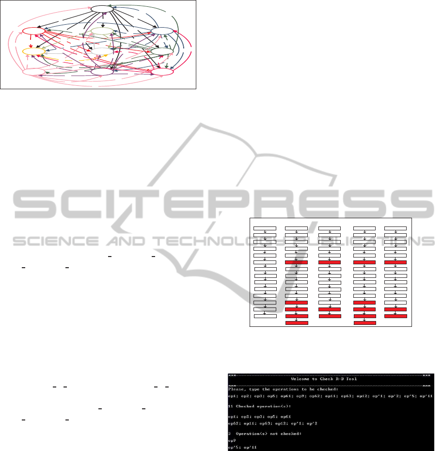
Example2. Verification of DRCS
As shown in Figure 7, from the distributed config-
uration (1,1) to (2,3) (resp. (3,3)), only op8 and
op’5;op’11 (resp. op9 and op’5; op’11) need to be
verified, the same operations have not to be checked
again. Further more, from the distributed configura-
tion (1,1) to (2,2) (resp. (3,2)), only operations op8
and op
′
6 ; op
′
8 ; op
′
10 ; op
′
11 (resp. op9 and op
′
6
; op
′
8 ; op
′
10 ; op
′
11 ) need to be verified, since the
others are similar.
(2,2)
op'10
op'11
op'8
op'6
op'1
op8
op61
op5
op3
op2
op1
(1,1)
op'4
op'3
op'2
op'1
op7
op61
op5
op3
op2
op1
(2,3)
op'11
op'5
op'2
op'1
op8
op61
op5
op3
op2
op1
(3,2)
op'10
op'11
op'8
op'6
op'1
op9
op61
op5
op3
op2
op1
(3,3)
op'11
op'5
op'2
op'1
op9
op61
op5
op3
op2
op1
op11
op62
op12
op63
op11
op62
op12
op63
op11
op62
op12
op63
op11
op62
op12
op63
op11
op62
op12
op63
Figure 7: Verification of DRCS:FESTO and EnAS.
Example3. Simulation of the configuration (3,3)
Figure 8: Simulation of the configuration (3,3).
Let us assume that the user introduces operations cor-
responding to the execution of the distributed config-
uration (3,3). Let us assume that the tool has verified
firstly the distributed configuration (1,1), so a search
in a file containing checked machines will be done. If
a sequence of operations with precedence relationship
already exists, it is not necessary to check it again.
Otherwise, it will be forwarded to the prover. As
shown in Figure 8, the sequence of operations (op1;
op2; op3; op5; op61) and (op62; op11; op63; op12;
op’1; op’2) have already been checked and the oper-
ations (op9) and (op
′
5 ; op
′
11) have to be verified.
PECCS2015-5thInternationalConferenceonPervasiveandEmbeddedComputingandCommunicationSystems
130

Figure 9 shows two curves corresponding to the
comparison between verification process with and
without using “Check R-B”. The values of the ab-
scises axis correspond to the distributed configura-
tions when the system runs two times ((1,1), (2,2),
(2,3), (3,2), (1,2), (3,3), (4,4), (3,1), (1,3), (2,1)) in
order. The ordinate axis correspond to the number of
checked operations. The curve in blue corresponds
to the verification without “Check R-B”. The curve
in pink corresponds to the optimal verification using
“Check R-B”. It is important to note that the num-
ber of checked operations decreases gradually until
the value zero when we use the Check R-B tool as
compared to a direct verification without Check R-B.
0
2
4
6
8
10
12
14
16
18
(1,1)
(2,2)
(2,3)
(3,2)
(1,2)
(3,3)
(4,4)
(3,1)
(1,3)
(2,1)
(1,1)
(2,2)
(2,3)
(3,2)
(1,2)
(3,3)
(4,4)
(3,1)
(1,3)
(2,1)
Distributed Configurations
Number of Checked Operations
Figure 9: Comparison between verification process with
and without using “Check R-B”.
8 CONCLUSION
This paper deals with the modeling and verification
of distributed multi-agent reconfigurable control sys-
tems following the B method. We affect to each sub-
system a CA to apply local automatic reconfigura-
tions, and a CA for any coordination between systems
in order to guarantee safe and adequate distributed
reconfigurations. We propose a “DR-B” formalism
to model DRCS. Further more, to reduce redundant
checking of different behaviors sharing similar oper-
ations, we applied the “Check R-B” tool.
Different directions can be mentioned as further
work. First of all, we plan to generate the C code for
each developed B machine. We plan also to develop
a graphical tool that allows the efficient modeling and
verification of reconfigurable systems with “DR-B”.
REFERENCES
http://aut.informatik.unihalle.de/forschung/testbed/.
Abrial, J.-R. (1996). The B-Book. Cambridge University
Press.
Angelov, C., Sierszecki, K., and Marian, N. (2005). De-
sign models for reusable and reconfigurable state ma-
chines. volume 3824, pages 152–163. 3th Interna-
tional Conference on Embedded and Ubiquitous Com-
puting.
khalgui, M., Mosbahi, O., Hanisch, H., and Li, Z. (2012).
A multi-agent architectural solution for coherent dis-
tributed reconfigurations of function blocks. Journal
of Intelligent Manufacturing, 23:2531–2549.
Oueslati, R., Mosbahi, O., Khalgui, M., and Ben Ahmed, S.
(2014). New solutions for modeling and verification
of b-based reconfigurable control systems. pages 749–
757. 11th International Conference on Informatics in
Control, Automation and Robotics.
ModelingandVerificationofB-basedDistributedReconfigurableControlSystems
131
