
CHAMELEON
New Object Oriented Solution for Adaptive Control Systems
Asma Nafti
2,3
, Mohamed Romdhani
1,3
and Mohamed Khalgui
1,3
1
University of Carthage, Carthage, Tunisia
2
FST Faculty, University of Tunis El Manar, Tunis, Tunisia
3
LISI Laboratory, INSAT Institute, Tunis, Tunisia
Keywords:
Real-time, Reconfiguration, Adaptive Control System, CHAMELEON System, Memory, Optimization.
Abstract:
The paper deals with a new Object Oriented Solution for Adaptive Control Systems having as name
CHAMELEON. The CHAMELEON system provides more flexibility and a gain in memory compared to
the Classical Oriented Object Approach. Firstly, we give a formalization of the solution. Then, we propose a
CHAMELEON meta-model and a sequence diagram to emphasize the dynamic aspects. Finally, an evaluation
is done in order to highlight the performance of the proposed approach.
1 INTRODUCTION
Embedded systems are playing an increasing role in
our daily life. They also affect different economic
areas such as transport, telecommunications, avion-
ics, etc. These systems are characterized by rigor-
ous functional and performance constraints which are
mainly imposed by their changing operational envi-
ronment. Thanks to the control theory, many ad-
vances have been accomplished yet in the streamline
of the mastery of the specification and the implemen-
tation of both functional and reactive aspects of em-
bedded and real-time systems. However, the changing
requirements of the context and the variation of exe-
cution environments invoke the need to develop adap-
tive control systems. An adaptive control system is a
system that is able to reconfigure its behavior or its
architecture at runtime in order to meet (or to adapt
to) the context change. Several research studies have
focused on the development of recongurable control
systems (Zhuo and Prasanna, 2008), (O. Lysne and
Skeie, 2008), (W. Jigang and Wang, 2007). These
studies have dealt with many kinds of reconguration
such as static and dynamic configurations. None of
those works, to our best knowledge, has addressed
the problem of building an adaptive and dynamically
reconfigurable architecture framework for real-time
systems at runtime. Our contribution consists of de-
signing CHAMLEON which a new Object Oriented
infrastructure for the design and the implementation
of control systems. CHAMELEON shifts the classi-
cal object oriented paradigm to allow extreme flexible
way of defining objects, their behavior and collabo-
ration, thereby reducing memory consumption. The
paper is structured as follows: Section II deals with
the state of the art. The Case study is mentioned
in section III. Section IV presents our contribution
which consists in modeling the recongurable embed-
ded systems by chameleon system. Section V de-
scribes the meta-model and the sequence diagramme
of CHAMELEON system. We evaluate our proposi-
tion in section VI.
2 STATE OF THE ART
Nowadays, several research approaches have been
studied for the implementation of adaptive control
software: J. Cobleigh and Al. Wise proposes a hierar-
chical self- adaptive software model for robot systems
with fault tolerances (Cobleigh and al, 2002). D. Gar-
lan, B. Schmerl, and P proposes Rainbow that con-
sists of a two layer framework with an external fixed
control loop for architecture based adaptation using
utility theory (Garlan and Steenkiste, 2004). Other
approaches focus on component adaptations such that
K-components (Dowling and Cahill, 2004). Many
works has been done in order to develop extending
middlewares with self-adaptation capabilities. Adap-
tive CORBA Template (Sadjadi and McKinley, 2004)
focuses on CORBA applications transparently weav-
297
Nafti A., Romdhani M. and Khalgui M..
CHAMELEON - New Object Oriented Solution for Adaptive Control Systems.
DOI: 10.5220/0005244902970304
In Proceedings of the 5th International Conference on Pervasive and Embedded Computing and Communication Systems (PECCS-2015), pages
297-304
ISBN: 978-989-758-084-0
Copyright
c
2015 SCITEPRESS (Science and Technology Publications, Lda.)
ing adaptive behavior into object request brokers at
runtime. Zhang and Cheng (Zhang and Cheng, 2006)
introduced an approach to create formal models of
adaptive programs behavior for analysis and imple-
mentation synthesis. Their approach separates spec-
ifications of adaptive and non-adaptive behavior by
simplifying their use. Using models as formal spec-
ifications of self-adaptive software systems has been
also proposed.Genie (N. Bencomo and Blair, 2008)
uses architectural models to support generation and
execution of adaptive systems for component-based
middlewares.
Although these contributions are interesting, we
believe they are limited when real-time configuration
becomes a requirement for the adaptation of the sys-
tem to its environment. The current paper proposes an
original CHAMELEON-based solution for a required
flexibility of the software as well as the optimal man-
agement of the used memory.
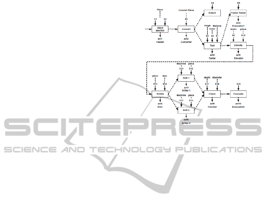
3 CASE STUDY: FESTO MPS
We present in this section the Benchmark Produc-
tion System FESTO (J.F. Zhang and Mosbahi, 2012)
(Khalgui, 2010) developed at Martin Luther Univer-
sity in Germany . Festo MPS is a platform used
by different universities for research and education
goals. Its platform is composed of three units (Fig-
ure 1): (i) Distribution Unit: composed of Pneumatic
Feeder and Converter to forward Cylindrical Work-
pieces from Stack to Testing Unit. (ii) Testing Unit:
composed of Detector, Elevator and Shift-Out Cylin-
der. It performs the checking of Workpieces for their
Height, Material Type, and Color. (iii) Processing
Unit: Workpieces that pass Testing Unit successfully
are forwarded to Rotating Disk of this unit for drilling.
We assume in this research work two drilling ma-
chines Drill1 and Drill2. Drill1 performs a simple
piercing whereas Drill2 performs a tapped piercing
of workpieces. Depending on the workpieces type,
the rotation of the Wick is equal to 15 rotations/s
for aluminum one and 20 rotations/s for bronze and
steel one. The result of the drilling operation is next
checked by a checker and finally the finished product
is removed from the system by an evacuator. To im-
plement actions performed by the drilling machines
Drill1 and Drill2, we propose the following set of
action methods: (i) On: to activate Drill1 or Drill2,
(ii) DownDo: to pierce a simple hole using the Drill1
Wick, (iii) Downt: to pierce a tapped hole using the
Drill2 Wick, (iv) Up: to elevate the Drill1 Wick or
Drill2 Wick after piercing, (v) Trans: to translate the
workpiece in order to drill a second hole, (vi) Of:
Figure 1: Operation of system FESTO. (M. Khalgui, 2010).
to deactivate Drill1 or Drill2. We use the attributes:
(i) Nbtour to indicates the number of Wick tour per
second which depends on Type of the workpiece,(ii)
Depth to indicate the depth of the hole pierced.
In our case study, 27 production modes of FESTO
MPS are considered according to Color c, Height h
and Types t of pieces. We cite the following cases:
• Case1: If c= ”red”, 10 =< h <= 20 and t= ”steel”
then, the drilling machine Drill2 is used with a
rotation equal to 20 rotations/s to do a tapped hole
having a depth of 5 cm in a single pass,
• Case2: If c= ”blue”, h > 30 and t= ”aluminum”
then, Drill1 and Drill2 are used with a rotation
equal to 15 rotations/s to do the piercing. In the
first time, Drill1 does a simple hole having a depth
of 10 cm in two passes.
The trivial implementation of the 27 production
modes requires logically 27 software classes with a
valuable number of attributes and constants. Since we
are dealing with embedded systems with limited fre-
quency of processor and size of memory, the imple-
mentation of these 27 classes is not an easy solution to
deploy: this is the real-time problem that the current
paper deals with. All these problems lead us to pro-
pose an optimal solution that reduces the complexity
of the system by representing it with a one reconfig-
urable class that will cover all system configurations
and minimize the memory consumption besides the
number of context switching: It is the CHAMELEON
class that will be presented in the next section. Note
that the CHAMELEON class is an original concept
for reconfigurable software systems which is not pro-
posed in related works, and presents today a new
PECCS2015-5thInternationalConferenceonPervasiveandEmbeddedComputingandCommunicationSystems
298

challenge for the optimal implementation of reconfig-
urable systems.
4 CHAMELEON META MODEL
4.1 A Paradigm Shift in Modeling
Run-time Reconfiguration
Among the criteria that we must ensure for a reconfig-
urable embedded system is the flexibility and also the
reduction of the memory consumption since embed-
ded systems have a reduced memory size. To solve
these problems, we propose to present reconfigurable
embedded real-time systems by a new type of class
to be named CHAMELEON class. CHAMELEON is
a class that changes automatically its behavior from
a mode to another. It contains all the common meth-
ods for different execution modes and a set of spe-
cific methods for each configuration. Instead of load-
ing the system by many objects representing the dif-
ferent configurations, we create one object related to
the CHAMELEON class which reduces certainly the
memory consumption compared to the oriented ob-
jected approach. When we switch from a configura-
tion to another one, we just activate the specific meth-
ods of the new configuration and deactivate those of
the previous one. This reduces the number of con-
text switching and gives more flexibility for the sys-
tem. A CHAMELEON class inherits from the Thread
class. To handle all possible reconfiguration forms,
the CHAMELEON class has three tables allowing the
run-time reconfigurations of its methods as well as at-
tributes for a flexible adaptation to changes in the en-
vironment according to user requirements.
4.2 Formalization of CHAMELEON
Class
CHAMELEON is a new type of Object Oriented
Classes for flexible systems that should be recon-
figured at run-time. Three possible reconfiguration
forms can be applied on CHAMELEON: (i) Method
reconfiguration: activation or deactivation of methods
at run-time, (ii) Scheduling reconfiguration: modifi-
cation of the execution orders of methods inside the
CHAMELEON object, (iii) Attribute-Constant recon-
figuration: the modification of values according to
user requirements.
4.2.1 Method Reconfiguration
The different possible reconfigurations of methods
can be represented in the specification level by a finite
state machine FSM
meth
. A FSM
meth
is composed of n
states such that each one represents a subset of meth-
ods to be active for the implementation of the class at
a particular time t. Each transition in this state ma-
chine represents a reconfiguration scenario allowing
the addition-removal of methods. We implement this
finite state machine FSM
meth
by an architecture Table
to be denoted by AT. AT is a matrix (n,p) of integers
where n is the number of system configurations and p
is the number of all its methods ( active and deactive).
AT is formed from the finite state machine FSM
meth
,
such that each state represents a row in the table AT.
The method reconfiguration is applied according to
the table AT, which is given by:
AT[i][ j] =
1, if M
j
∈ A
i
,
0, i f M
j
/∈ A
i
(1)
Where:
• M
j
: the j
th
method of the system, j=1..p,
• Ai: the i
th
configuration of the system (e.g. a set
of active methods), i=1..n.
Note that an object is attached to each method M
j
(j=1..p). When a method is activated by a given con-
figuration A
i
(i=1..n), the corresponding cell in the ta-
ble AT takes 1 and its corresponding object is instan-
tiated. When a method is deactivated, the correspond-
ing cell in the table AT takes the value 0 and the cor-
responding object is deleted. Finally, we denote by
A
i
(t) the i
th
implementation of the system at a partic-
ular time t.
Running Example 1. To simplify, We assume that
the Festo MPS system does three types of piercing
(e.g. three configurations). We suppose that the sys-
tem runs at a particular time t1 with the configuration
A
1
(t1) such that :
A
1
(t1) = {On, Downt,U p,Of}
when a new reconfiguration scenario is applied at
time t2, the system changes to a new configuration
A
2
(t2) such that:
A
2
(t2) = {On, Down,U p, Trans,Of}
The corresponding state machine is composed of
three states as follows (Figure 2):
Since FSM
Meth
contains three states, AT is com-
posed also of three rows (Table 1).
Table 1: Architecture table for FESTO MPS.
M on down downt up trans of
A1 1 0 1 1 0 1
A2 1 1 1 1 1 1
A3 1 1 0 1 1 1
CHAMELEON-NewObjectOrientedSolutionforAdaptiveControlSystems
299
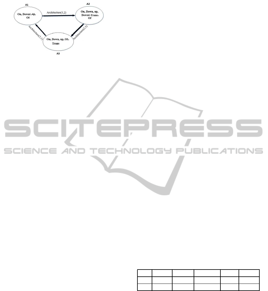
Figure 2: FSM of method reconfiguration for FESTO MPS.
Each state in the FSM
meth
and its corresponding
row in AT, is a configuration of the system FESTO
MPS. At a time t, if the system is in architecture A
3
,
only the methods On, Down, Up and Case1 are acti-
vated and its corresponding cells in the table AT takes
the value 1 whereas the other cells takes 0. When the
system changes from the architecture A
3
to A
1
, the
method Downt is activated and its corresponding cell
in AT takes the value 1 whereas the method Down and
Trans are deactivated and their corresponding cells in
AT take 0.
4.2.2 Scheduling Reconfiguration
The scheduling reconfiguration is a reconfiguration
allowing the modification of the methods schedul-
ing according to configuration requirements. For
each state of FSM
meth
in the method reconfiguration
level. We define down a new nested state machine
NSM
h
sched
, (h=1..n) in the scheduling reconfiguration
level to show all possible scheduling of active meth-
ods in the upper level. We supposethat each NSM
h
sched
is composed of k
h
states. Each state of NSM
h
sched
is a finite state machine FSM
hi
sched
,i = 1..k
h
that is
composed of q
h
states such that each one is rela-
tive to an active method. FSM
hi
sched
represents a pos-
sible scheduling of the active methods relative to a
configuration in FSM
meth
(Figure 3). We implement
NSM
h
sched
by a scheduling table to be denoted by ST
h
such as a state in the first is a row in the second. ST
h
is
a matrix (k
h
, q
h
) of integers such that q
h
is the number
of activated methods and k
h
is the number of all pos-
sible scheduling for q
h
activated methods. The values
in the table ST
h
indicate the execution order of meth-
ods. Indeed, each box in ST
h
indicates the order of
each call for an activated method. For each configu-
ration, we have a set of methods to be executed. The
scheduling table shows all the possible execution or-
ders of these methods. If a method is called more than
one time, then ST
h
indicates the order of each call. The
scheduling reconfiguration is applied according to the
table ST
h
given by:
∀ 1 =< i <= k
h
,1 =< j <= q
h
,1 =< h <= n :
ST
h
[i][ j] = {a
0
..a
x
}
(2)
where:
• a
0
..a
x
: the set of the execution order of the
method M
j
, j = 1..q
h
for the i
th
scheduling of
FSM
h
sched
.
We denote by S
hi
(t) the i
th
scheduling of the active
methods relative to the h
th
architecture A
h
(t) at a par-
ticular time t.
Running Example 2. At time t1, if the configura-
tion A1(t1) is loaded, then the activated methods are
On, Downt, Up, Of. The scheduling in this case is
assumed to be:
S
11
(t
1
) = {{1},{2},{3}, {4}}
Indeed, 1, 2, 3 and 4 indicates respectively the
execution order of On, Downt, Up and Of. At time
t2, if the configuration A
2
(t2) is loaded, then the
activated methods are On, Down, Downt, Up, Trans,
Of. For this configuration, there are two scheduling
for FESTO MPS which are:
S
21
(t
2
) = {{1, 7},{2,4},{8,10},{3,5, 9,11},{6},
{12, 13}}
S
22
(t
2
) = {{1, 5},{2}, {6}, {3, 7}, {4},{8,9}}8, 9}}
For example, the method Up is called 4 times to do
two holes having a depth equal to 10 cm in two passes.
The values 3, 5 indicate the execution order of Up to
do the first hole for the first pass and the second one.
The values 9, 11 are the execution orders of Up to
do the second hole for the first pass and the second
one. The table ST
2
is formed from the NSM
2
sched
. It
is composed of 6 columns which are the number of
active method and two rows that indicate the possible
schedulings for the architecture A
2
(Table 2).
Table 2: Scheduling table ST2 for FESTO MPS.
on down downt up trans of
1,7 2,4 8,10 3,5,9,11 6 12,13
1,5 2 6 3,7 4 8,9
4.2.3 Data Reconfiguration
The data reconfiguration is a reconfiguration allow-
ing the modification of values of attributes according
to configuration requirements. The data configuration
represents all the data values related to active meth-
ods for a given configuration. It is given by the ta-
ble named Data table DT
hi
, h=1..n and 1 =< i <= k
h
.
DT
hi
corresponds to a particular architecture table AT
and scheduling table ST
h
. It is a matrix (l
h
,t
h
) of inte-
gers such that l
h
is the number of elements in a subset
PECCS2015-5thInternationalConferenceonPervasiveandEmbeddedComputingandCommunicationSystems
300

Figure 3: states machines for CHAMELEON system.
of the active methods, l
h
= 1..q
h
, t
h
is the number of
active attribute related to these methods. This table
contains the set of values of each active attributes for
a given scheduling. The data reconfiguration is ap-
plied according to the table DT
hi
, which is given by:
∀ 1 =< i <= q
h
,1 =< j <= t
h
,h = 1..n,
1 =< l <= k
h
DT
hl
[i][ j] = {v
0
..v
y
}
(3)
Where:
• y: the executions number of each activated
method,
• v
0
..v
y
: indicate the different value of the attribute
j for the different executions of the method i in
the same fixed scheduling (e.g. the method i is
executed y times in this scheduling).
Note that an object is attached to each variable.
When a variable is activated by a given configuration
A
h
and a scheduling S
hi
, it will be mentioned in the
table DT
hi
with its values for each activated method
according to the fixed scheduling. In fact, when the
system changes from a configuration to another, we
activate a set of variables and deactivate others. we
denote by D
hi
(t) the data configuration relative to the
i
th
scheduling S
hi
(t) of the h
th
architecture A
h
(t) at a
particular time t.
Running Example 3: When the Festo MPS is run-
ning in the architecture A
2
and in the first corre-
sponding scheduling S
21
, the corresponding Data Ta-
ble DT
21
is as follow ( Table 3):
Table 3: Scheduling table ST2 for FESTO MPS.
Method
variable
depth nb tour
down 5, 10 15, 15
downt 5, 10 15, 15
This table gives the values of variables depth and
nbtour when calling the method Down and Downt.
In this configuration, the drilling machine makes the
piercing of two holes for aluminum workpieces, the
first is a simple hole and the second is tapped.Firstly,
the method Down is called to do the first pass of the
simple hole with a depth equals to 5 and a number
of wick rotation equals to 20. In the second time,
the method Down is called for the second pass with a
depth of 10 and a number of rotation equal to 20. The
same is repeated for the second drill hole by calling
Downt.
The data configuration in this case is as follows:
D
21
(t
2
)={{{5,10},{ 15,15}},{{5,10},{15,15}}}
Note that this classification covers all pos-
sible reconfigurations form that we can apply
to adapt a chameleon class to its environment:
(i):additionel/remove and modification of execution
order of methods,(ii) update of attributes. So, the i
th
configuration (i=1..n) of the CHAMELEON class CH
at time t is given by:
CH(t) = {A
i
(t),S
ij
(t),D
ij
(t),AT,ST
i
,DT
ij
} (4)
• j: the number of the schedulings relative to the
configuration i, j = 1..k
h
5 UML BASED DESIGN
5.1 Meta-model Caracterisation
Based on the formalization done in the previous sec-
tion, we elaborate the CHAMELEON meta-model
given by Figure 4.
The CHAMELEON is composed of one architec-
ture table AT which is composed of n architecture
configuration (.e.g a set of active methods). For each
CHAMELEON-NewObjectOrientedSolutionforAdaptiveControlSystems
301

Figure 4: Meta-model of CHAMELEON system.
Figure 5: Sequence diagram for initialisation of system ta-
bles.
architecture configuration, there is n scheduling tables
ST. Each table ST contains all possible scheduling for
the active methods. For each scheduling is related one
data table DT that represents a data configuration(.e.g
a set of active data).
5.2 Sequence Diagram
To illustrate the dynamic aspect and all the possible
reconfiguration, we detail in this section the sequence
diagrams. At the first time, the user calls initmethod-
table(), initschedulingtable(), initdatatable() and to
initialize respectively AT, ST, DT (Figure 5). when an
event happens, the system will pass from an architec-
ture i to a another j. The CHAMELEON method calls
the method architecture(i,j). Architecture(i,j) consults
the table AT and points to the next row to determine
which methods should be activated (Figure 6).
The CHAMELEON method calls data(j) that will
do the data reconfiguration. Data(j) points to the data
table DT and activates the attributes related to acti-
vated methods.(Figure 7). Then the CHAMELEON
Figure 6: sequence diagram of architecture configuration
for CHAMELEON system.
Figure 7: sequence diagram of data configuration for
CHAMELEON system.
methods call the method scheduling(j) which consults
the scheduling table ST relative to the current archi-
tecture configuration and calls the action methods in
the execution order mentioned in ST (Figure 8).
Once the configuration is done, the method ar-
chitecture(i,j) deactivates the action methods previ-
ously activated, the method data(j) deactivates the at-
tributes.(Figure 9).
PECCS2015-5thInternationalConferenceonPervasiveandEmbeddedComputingandCommunicationSystems
302
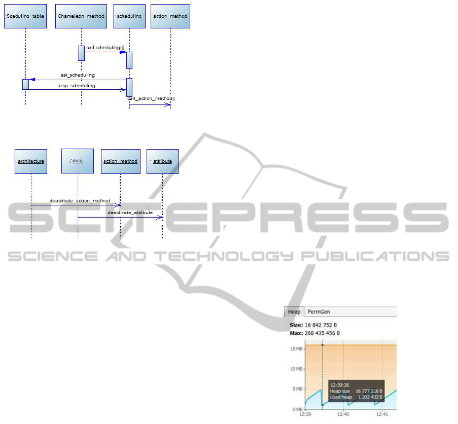
Figure 8: sequence diagram of scheduling for
CHAMELEON system.
Figure 9: sequence diagram of method and data deactiva-
tion in the CHAMELEON system.
6 EVALUATION
The goal of this evaluation is to get early performance
measurements of the CHAMELEON implementation
impact when used in modeling a real-time applica-
tion. We considered the Festo MPS benchmark pro-
duction system which has been presented earlier in
section III as a running example. We also chosen
the Java programming language and its related perfor-
mance tool-set mainly JConsole and Java VisualVM
as a technical infrastructure for this evaluation.
6.1 Preparing the Testbench
In order to assess the impact of the CHAMELEON
approach of FESTO MPS production system, we have
produced two alternative models for the FESTO MPS
system:
6.1.1 A First ”CHAMELEON less” Model
This model implements the FESTO system using a
classical Object Oriented approach. In this model, an
abstract Java class called Drilling encapsulates the set
of the methods that correspond the basic behaviors of
FESTO and this class is refined in terms of more spe-
cific classes in order to enrich the basic behavior or
redefine some of the polymorphic methods.
6.1.2 A Second CHAMELEON Based Model
This model implements the FESTO system using the
CHAMELEON meta-model concepts presented in IV.
In this model, the Drilling objects are Java objects
that do not have any known methods at compile-time
but those are ”injected” dynamically at run-time. The
dynamic configuration and reconfiguration of the ob-
jects at run-time according to the actual context is the
key feature of CHAMELEON. In terms of OO pro-
gramming, this feature should promote an extreme
degree of behavior reuse and ensures that objects
are lightweight. The CHAMELEON based model of
FESTO MPS system has been written in Java.
6.2 Results
We highlight first that both the polymorphism and the
CHAMELEON model of FESTO MPS system do the
same functionality. Performance analysis results ob-
tained using Java Visual VM of the two models are
shown in the figures below. We focus mainly on mem-
ory consumption since CPU performance shows that
there is no remarkable differences between the two
models.
Figure 10: Consumption by FESTO MPS in the polymor-
phism model.
We notice that the CHAMELEON model of
FESTO optimizes the memory (heap) consumption.
The required heap size is only of 1202 KB (figure 10).
In the case of the CHAMELEON less model the re-
quired heap size is 1341 KB (Figure 11).
The CHAMELEON model provides a minimiza-
tion of memory consumption equal to 10 percent
compared to the polymorphism model.
6.3 Explanation
The CHAMELEON approach optimizes the memory
consumption since, unlike the OO approach, the ob-
jects does not have a set of known methods at com-
pile time. In the OO approach, each object that is
CHAMELEON-NewObjectOrientedSolutionforAdaptiveControlSystems
303

Figure 11: Memory (Heap) Consumption by FESTO MPS
in the CHAMELEON model.
an instance of the Drilling class has its self copy of
attributes and methods. This duplication of contexts
causes extra memory consumption that may be aggra-
vated when the application involves a large number
of collaborating objects. The memory performance
may also be negatively impacted by applications that
involve a large number of methods or heavy process-
ing methods. However, in the CHAMELEON sys-
tem there is an additional memory footprint required
for the dynamic management of object contexts (data,
methods, configurations). But the memory cost of
these meta data structures are insignificant when com-
pared with the memory cost of application objects.
7 CONCLUSION
In this paper, we present a new approach for mod-
eling reconfigurable embedded systems which is
CHAMELEON meta-model. This concept covers all
possible reconfiguration forms that can be applied
at run-time to adapt the system to its environment
and the user requirement. CHAMELEON classes
can add/remove at run-time, modify their execution
orders, update attributes and constants. We have
proven that this approach minimizes greatly the mem-
ory consumption compared to the polymorphism ap-
proach especially when the system has many configu-
rations. We plan in the future work to enrich this con-
cept with several features such as real-time, memory,
power, quality. We plan also to study the collabora-
tive CHAMELEON classes that should synchronize
their run-time behavior in order to prevent any inco-
herent configurations. Finally, we plane to new solu-
tion for optimal teste of CHAMELEON classes since
this kind of verification is not exhaustive.
REFERENCES
Cobleigh, J. and al (Nov 2002). Containement units: a hi-
erarchically composable architecture for adaptive sys-
tems. ACM SIGSOFT Software Engineering Notes.
Dowling, J. and Cahill, V. (2004). Self-managed decen-
tralised systems using k-components and collabora-
tive reinforcement learning. CM SIGSOFT workshop
on Self-managed systems.
Garlan, B. S. and Steenkiste, P. (2004). Rainbow:
architecture-based self-adaptation with reusable in-
frastructure. International Conference on Autonomic
Computing.
J.F. Zhang, M. Khalgui, Z. L. and Mosbahi, O. (2012). R-
tnces: a novel formalism for reconfigurable discrete
event control systems. IEEE Transactions on Systems,
Man and Cybernetics, Part A: Systems and Humans.
Khalgui, M. (2010). Nces-based modelling and ctl-based
verification of reconfigurable embedded control sys-
tems. Computers in Industry 61, pp.198212.
M. Khalgui, O. Mosbahi, Z. L. H. M. H. (2010). Reconfig-
urable multi-agent embedded control systems: From
modelling to implementation. IEEE Transactions on
Computers.
N. Bencomo, P. Grace, C. F. D. H. and Blair, G. (2008).
Genie: supporting the model driven development of
reflective, component-based adaptive systems. Inter-
national conference on Software engineering.
O. Lysne, J.-M. Montanana, J. F. J. D. T.-M. P. and Skeie, T.
(2008). An efficient and deadlock-free network recon-
figurable protocol. IEEE Transactions on Computers.
Sadjadi, S. and McKinley, P. (2004). Sact: an adap-
tive corba template to support unanticipated adapta-
tion. International conference on Distributed Comput-
ing Systems.
W. Jigang, T. S. and Wang, X. (2007). Integrated row
and column rerouting for reconfiguration of vlsi ar-
rays with four-port switches. IEEE Transactions on
Computers.
Zhang, J. and Cheng, B. H. C. (2006). Model-based devel-
opment of dynamically adaptive software. 28th inter-
national conference on Software engineering.
Zhuo, L. and Prasanna, V.-K. (2008). High-performance
designs for linear algebra operations on reconfigurable
hardware. IEEE Transactions on Computers, vol.57,
no.8.
PECCS2015-5thInternationalConferenceonPervasiveandEmbeddedComputingandCommunicationSystems
304
