
Self-scaling Kinematic Hand Skeleton for Real-time 3D Hand-finger Pose
Estimation
Kristian Ehlers and Jan Helge Kl
¨
ussendorff
Institute of Computer Engineering, Universit
¨
at zu L
¨
ubeck, L
¨
ubeck, Germany
Keywords:
Hand-finger Pose Estimation, Self-scaling Kinematic Skeleton, Hand Skeleton Tracking, Gesture Detection
Abstract:
Since low cost RGB-D sensors have become available, gesture detection has gained more and more interest in
the field of human computer and human robot interaction. It is possible to navigate through interactive menus
by waving one’s hand and to confirm menu items by pointing at them. Such applications require real-time
body or hand-finger pose estimation algorithms. This paper presents a kinematic approach to estimate the
full pose of the hand including the angles of the finger joints. A self-scaling kinematic hand skeleton model
is presented and fitted into the 3D data of the hand in real-time on standard hardware with up to 30 frames
per second without using a GPU. This approach is based on the least-square minimization and an intelligent
choice of the error function. The tracking accuracy is evaluated on the basis of a recorded dataset as well as
simulated data. Qualitative results are presented to emphasize the tracking ability under hard conditions like
full hand turning and self-occlusion.
1 INTRODUCTION
Gestures are part of our daily lives, e.g., some peo-
ple gesticulate while they are talking to emphasize
their intention and young children point at things they
would like to have. People greet each other over larger
distances by simply waving their hand and policemen
control the traffic with certain arm movements.
As gestures are a common, intuitive, and simple
form of communication, human pose estimation and
gesture detection are gaining more and more inter-
est in the field of human computer interaction (Han
et al., 2013). They can be used for the touchless con-
trol of applications or to play games on consoles like
the Xbox 360 in combination with the low-cost RGB-
D sensor Microsoft Kinect, which can generate a 3D
point cloud of the scene in front of the camera. In such
use cases, gestures are defined on the basis of move-
ments or the arrangement of body parts like swiping
the hand or jumping.
Regarding applications with limited space in front
of the camera, full body movements are unfavorable.
Therefore, specific poses of the hand and, in more de-
tail, the fingers are defined as hand or hand-finger ges-
tures. For instance, the thumbs-up gesture is used to
indicate that everything is fine and even sign language
is based on hand and hand-finger gestures.
The detection of both body gestures and hand-
finger gestures requires efficient algorithms to esti-
mate and classify full body poses or hand-finger poses
in real-time.
One of the major issues in estimating the pose of a
human skeleton is the large state space. For example,
the hand is a highly articulated object and it is often
modeled using at least 26 degrees of freedom (Erol
et al., 2007; ElKoura and Singh, 2003; Oikonomidis
et al., 2010).
However, this paper proposes an approach for full
hand-finger pose estimation based on a self-scaling
kinematic hand skeleton model: the positions of the
fingers’ joints and other features like the fingertips
as well as the joints’ angles are estimated by using
inverse kinematics and simple model data distances
to solve the formulated optimization problem. Fur-
ther, the model determines the wrist’s joint position
describing the relation between hand and arm. Since
the size of the human hand varies and a standard kine-
matic skeleton has a fixed size, the presented kine-
matic skeleton is scaled during the optimization pro-
cess. This approach uses the data of one single depth
camera and is not limited to human hands but can be
extended to arbitrary skeletons.
A support vector machine (SVM) is trained with
different hand-finger poses and used for the finger
gesture classification.
The pose estimation approach is evaluated in de-
tail with respect to fingertip tracking accuracy and
performance as well as the correct determination of
the hand’s configuration, i.e., the joints’ angles. De-
termining the wrist’s joint position requires the 3D
Ehlers K. and Klüssendorff J..
Self-scaling Kinematic Hand Skeleton for Real-time 3D Hand-finger Pose Estimation.
DOI: 10.5220/0005257501850196
In Proceedings of the 10th International Conference on Computer Vision Theory and Applications (VISAPP-2015), pages 185-196
ISBN: 978-989-758-090-1
Copyright
c
2015 SCITEPRESS (Science and Technology Publications, Lda.)

points of a small part of the arm. As is known to the
authors, the available datasets do not contain this in-
formation, which is why no usable datasets of anno-
tated hand skeletons and depth images are available
(Oikonomidis et al., 2010; Schr
¨
oder et al., 2013; Srid-
har et al., 2013; Qian et al., 2014). Therefore, ground
truth data is generated while robot-based movements
of a gypsum hand model are recorded and some hand
movements performed by a test subject are recorded
and annotated. In addition, the self-scaling ability is
evaluated and joint movements are simulated to de-
termine the correctness of the joint position estima-
tion. Moreover, the results of qualitative evaluation
and performance tests are presented.
Hence, the hand pose estimation is based on the
3D data of the hand an approach for the initial detec-
tion of the hand points is presented.
This paper is organized as follows: Section 2 de-
scribes related work on hand-finger pose estimation
and finger gesture detection and presents some of the
main differences to the developed method. An ap-
proach to detect the hand inside a 3D scene, the kine-
matic hand skeleton model including the finger pose
estimation approach, and a gesture classifier based on
the joints’ angles are presented in Section 3. Experi-
ments and detailed evaluations are given in Section 4
followed by the conclusion presented in Section 5.
2 RELATED WORK
There are several approaches to estimate the pose of
the human hand using RGB or RGB-D image data.
Some of them are based on large datasets, calculated
beforehand, or a specific hand model. Sometimes
markers have to be worn whereas other approaches
are completely markerless.
Ren et al. determine the hand pose in the form
of finger gestures by introducing the Fingers-Earth
Mover’s Distance as a distance metric for hand dis-
similarities (Ren and Yuan, 2011; Ren et al., 2011).
The fingers are matched on the basis of the hand shape
given by the depth image of the Kinect. The cur-
rent gesture is determined by template matching on
a dataset, recorded beforehand.
Athitsos et al. determine plausible 3D hand con-
figurations by formulating image database indexing
problems (Athitsos and Sclaroff, 2003). For this pur-
pose, they compute a large database consisting of syn-
thetic hand images by rendering 26 basic shapes of
an articulated hand model at different orientations.
Given the current hand image, the algorithm matches
the corresponding edge image with the database edge
images by determining image distances like the cham-
fer distance. The closest match directly represents the
current hand configuration.
Horaud et al. estimate a hand model based on 3D
data by matching an articulated hand shape model us-
ing robust point registrations with expectation condi-
tional maximization (Horaud et al., 2011).
De La Gorce et al. recover the 3D hand pose from
monocular images through the minimization of an ob-
jective function using a quasi Newton approach based
on a parametric hand model (Gorce et al., 2011). The
objective function includes texture and shading infor-
mation to handle self-occlusions and the well-defined
image formation process determines a synthetic hand
image as similar as possible to the current image
based on the articulated hand model and the RGB im-
age.
Oikonomidis et al. determine the hand skeleton
based on a particular model and Particle Swarm Op-
timization (PSO) (Oikonomidis et al., 2010; Oikono-
midis et al., 2011). The pose of the hand is determined
by the minimization of an error function using PSO,
whereby it is based on skin and edge feature maps of
the current hand image and hypothesized poses.
Besides the aforementioned methods, there are ap-
proaches that use markers to estimate the pose of the
hands. Thus, the approach of Wang and Popovi
´
c
is based on a glove, colored with a specific pattern,
and a recorded dataset containing rasterized glove im-
ages of natural hand poses (Wang and Popovi
´
c, 2009).
Therefore, the current hand pose is estimated by find-
ing the best matching image in the database with re-
spect to a robust distance metric. Schr
¨
oder et al. ex-
tend this approach to control an anamorphic robot
hand (Schr
¨
oder et al., 2012). They save the pose-
specific parameters of a kinematic hand model and
use them to render the corresponding glove images
needed for the pose estimation.
In (Keskin et al., 2011), the authors present a
randomized decision forest (RDF) approach for hand
pose estimation. They adapt the well-known body
pose estimation approach of (Shotton et al., 2011) and
train a decision forest with hand pose data. They ex-
tend their approach to a multi-layered RDF network
in (Keskin et al., 2012) by developing a hand shape
RDF. For each hand shape, a special RDF is trained
to determine the parts of the hand.
The aforementioned approaches are based on
large datasets recorded beforehand or calculated data
such as decision forests. They often need to be pro-
cessed by the GPU to achieve acceptable frame rates.
This paper presents a real-time approach running with
up to 30 frames per second (FPS) on standard hard-
ware without GPU acceleration.
Aristidou and Lasenby propose an algorithm to it-

eratively adapt the joints of a kinematic hand model
using inverse kinematics and a marker-based opti-
cal motion capturing system (Aristidou and Lasenby,
2010).
In (Schr
¨
oder et al., 2013), the authors use inverse
kinematics to fit a virtual hand model into the 3D
data of the hand. The model consists of a triangu-
lated mesh with a kinematic hand skeleton. A least-
squares optimization is used to adapt the model to the
3D point cloud. Therefore, the distance between the
model and the current data is determined by the point-
to-triangle distance.
In (Liang et al., 2012), the authors present a three-
step Iterative Closest Point (ICP) based approach for
hand pose estimation based on an articulated 3D mesh
model. The global motion estimation is performed by
overlaying the current hand data with the model data
using the ICP method on the current hand data and the
corresponding model’s visible mesh points. Further,
a fingertip estimation and inverse kinematics result in
a first aligned model. The final step is the articulated
ICP to align the mesh model and the real data.
Ballan et al. also fit meshed hand models with un-
derlying skeletons into 3D data and extend the appli-
cation to interactions of both hands with objects, e.g.,
holding a small ball or folding the hands. They use
multiple camera views to handle mutual occlusions
(Ballan et al., 2012). There are other approaches cov-
ering human-object interaction tasks like grasping,
hand manipulation tasks, or hand tracking for com-
puter aided design (Wang et al., 2011; Wang et al.,
2013; Zhao et al., 2013).
Nevertheless, this paper concentrates on the task
of hand-finger pose estimation and introduces a
kinematic model-based approach differing from the
named ones in all ways except the usage of a kine-
matic model but with the addition that it is self-
designed and extended. The kinematic skeleton is di-
rectly fitted into the visible hand data corresponding
to the hand’s surface. The offset between the hand
surface and the bones is ignored during the non-linear
least square optimization process and leads to a sim-
pler data-model distance as presented in (Schr
¨
oder
et al., 2013). This simplification speeds up the whole
pose estimation. Further, it allows to handle motion-
depending self-occlusions and just one optimization
process is needed. In addition, the kinematic model
is extended by an arm stub representing the pose in-
formation between hand and arm. One of the main
improvements with respect to other kinematic model
approaches like (Qian et al., 2014) is the model’s
self-scaling ability. The skeleton is scaled during the
whole estimation process and can handle every hand
size automatically.
To the authors’ knowledge, the approach of Qiang
et. al presented in (Qian et al., 2014) is the only
one that achieves a robust hand-finger pose estimation
with a speed up to 25 FPS. Qiang et. al use a kine-
matic hand motion model with 26 degrees of freedom
and combine the ICP and PSO optimization to realize
full articulated hand tracking based on the data of In-
tel’s Creative Interactive Gesture Camera. They use a
sphere-based hand model and sample the hand’s point
cloud down to 256 points to achieve real-time perfor-
mance.
Despite the resulting high number of 29 degrees of
freedom of the kinematic skeleton presented here, the
pose estimation runs in real-time with 30 FPS, limited
by the camera without any use of the GPU. In addi-
tion, the data of the hand is not sampled down. The
real-time performance of 30 FPS is achieved using the
nearly 16.000 points of the hand in a distance of 50 cm
to the camera as well as by using the 5.500 points
in a distance of 100 cm. The efficiency and the fact
that there is no need for previously calculated large
datasets allow for real-time performance and would
predestinate this approach for embedded applications.
For some approaches, multiple steps are necessary
to estimate the hand-finger pose, e.g., determination
of the hand shape or the finger tips followed by the de-
termination of the full hand pose (Liang et al., 2012;
Keskin et al., 2012). The presented approach needs
only one optimization process based on the simple
model data distance. Furthermore, the approach is not
limited to the application of the hand pose estimation
and it can deal with arbitrary kinematic skeleton mod-
els.
3 FINGER POSE ESTIMATION
The task of hand-finger pose estimation can be subdi-
vided into two major problems: finding the hand in-
side the 3D scene and determining the pose. This sec-
tion presents solutions for both problems. In the fol-
lowing, the full hand pose and the hand-finger poses,
including the joints’ angles of the fingers, are used
synonymously.
3.1 Initial Hand Detection
One of the most challenging tasks, apart from esti-
mating the full hand pose, is the initial localization of
the hand inside a given 3D scene. Often many restric-
tions are made to the scene and hands’ positions, e.g.,
cropping the whole scene or assuming the hand is the
closest object to the camera (Ren et al., 2011).

This paper presents a simple and more flexible ap-
proach assuming a static camera and only one human
being inside the scene facing the camera. The first
depth image is stored as reference. For each frame,
the difference image with respect to the reference im-
age is calculated. Afterwards, a blob detection is per-
formed and the largest blob is assumed to represent
the human being. In each step, the reference image is
adapted to the current scene by updating a depth value
if the current value is larger than the corresponding
one inside the reference image. After a while, the ref-
erence image represents the background. For a usable
pose estimation, the hands should be situated in front
of the human being. Thus, all points outside the blob
as well as all points with a larger depth value than
the mean depth value of the blob representing the hu-
man body reduced by a threshold of about 20 cm are
removed. It is assumed that the two largest remain-
ing blobs represent the hands. It is hard to distinguish
the hands on the basis of their positions only, e.g., the
arms can cross each other and a left hand facing the
camera with the back of the hand looks like a right
hand facing the camera with the palm. Hence, for ini-
tialization, it is assumed, that the palms of the hands
face the camera.
The blob of a hand is examined in a similar way as
presented in (Raheja et al., 2011). The estimation of
the center of the palm is based on the distance trans-
form and the palm-corresponding pixels are removed.
The left sub blobs seem to be the fingers and allow to
determine their tips. Since it is assumed that the open
hand is presented for the initial hand detection, there
have to be five finger blobs. The hand’s orientation
can be calculated by the mean value of the vectors de-
fined by the palm’s center and the fingertips. This in-
formation is used to initialize the kinematic skeleton’s
position and the orientation according to the z-axis of
the camera.
3.2 Kinematic Hand Skeleton
In this paper, hand-finger pose estimation is not re-
duced to the determination of the positions of specific
hand features like the fingertips or the center of the
palm. It rather tends to estimate the joints’ angles
using a self-scaling kinematic model approach which
also determines the joints’ positions.
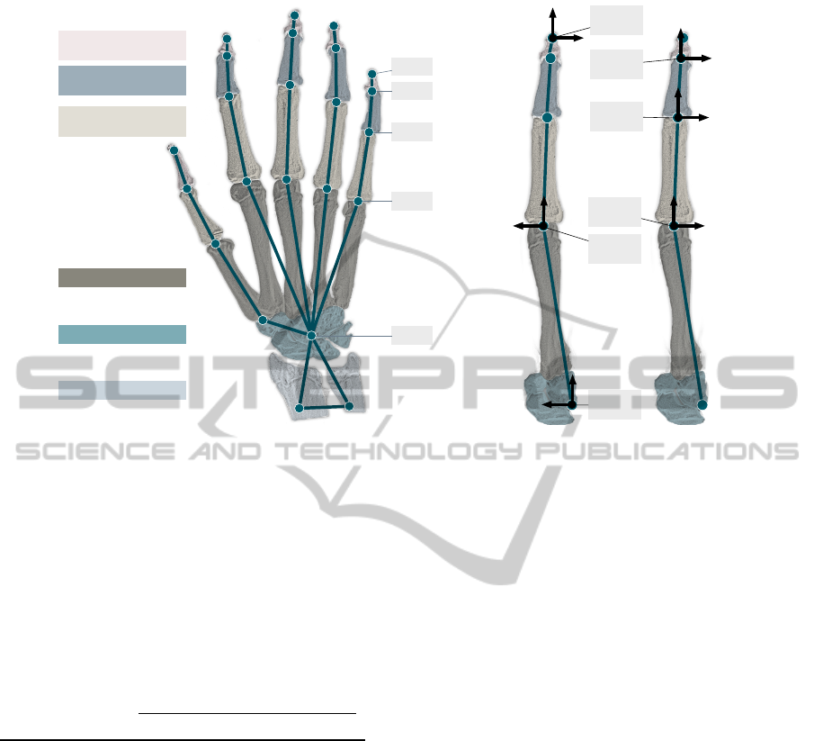
The kinematic hand model is designed in accor-
dance with the human hand skeleton illustrated in Fig-
ure 1. It consists of nodes and edges corresponding to
the skeleton’s joints and bones. The carpal bones and
the wrist joint are modeled by one central node (CEN)
forming the anchor of the whole model. The basic
coordinate system (CS
CEN
) of the model is situated in
the CEN where the z-axis faces the back of the hand,
the y-axis faces the thumb, and the x-axis completes
the right handed coordinate system facing the middle
finger. All fingers and the so called arm stub are con-
nected to the CEN. The arm stub represents the data
inside the hand’s 3D data corresponding to the lower
arm’s distal part. It consists of two nodes connected
to each other and to the CEN via edges. The wrist
can perform movements in two directions, i.e., flex-
ion and extension as well as abduction and adduction.
Therefore, the arm stub can be rotated around the z-
and the y-axis of the basic coordinate system.
Each finger is modeled by four edges correspond-
ing to the bones: the distal, medial, proximal pha-
langeal bones, and the metacarpal bone. The edges
connect the nodes representing the distal (DIP) and
proximal interphalangeal joints (PIP), the metacar-
pophalangeal joint (MCP), and the fingertip (TIP).
The edge representing the metacarpal bone is directly
connected to the central node. Each finger is allowed
to perform extension and flexion in all three joints as
well as abduction and adduction in the MCP.
To keep the model simple, the thumb is treated
as a normal finger, although it has got no medial
phalangeal bone. Hence, it is modeled in a way
that the model’s distal phalangeal edge corresponds
to the thumb’s phalangeal bone, the model’s medial
phalangeal edge corresponds to the thumb’s proxi-
mal phalangeal bone, and the model’s proximal pha-
langeal edge corresponds to the thumb’s metacarpal
bone. The model’s metacarpal edge bridges the dis-
tance between the thumb’s carpometacarpal joint and
the CEN. Consequently, in contrast to the fingers’
carpometacarpal joints, the thumb’s carpometacarpal
joint is modeled to be flexible in two directions.
The kinematic hand model is described with the
aid of the Denavit-Hartenberg (DH) transformations.
If the joints’ coordinate systems are situated in accor-
dance with the DH conventions, the transformation
from a coordinate system CS
i
to another one CS
i+1
can be described with the following four parameters:
d - offset between both coordinate systems’ origins
along the z
i
-axis, θ - rotation angle around the z
i
-axis
to overlay x
i
and x
i+1
, a - offset between both coor-
dinate systems’ origins along the x
i+1
-axis, and α -
rotation angle around the x
i+1
-axis to overlay x
i
and
x
i+1
. The rotation inside a joint is given by the angle
θ around the z-axis of the joint’s coordinate system.
Each finger is modeled by a kinematic chain con-
sisting of five coordinate systems, one for each joint’s
movement axis and one for the fingertip. Figure 1(b)
illustrates the way the model is placed inside the hand
based on the back view of the right hand. The first co-
ordinate system (CS
MCP1
) is situated at the MCP node
Distal Phalangeal
Bones
Middle Phalangeal
Bones
Proximal Phalangeal
Bones
Metacarpal Bones
Carpal Bones
Carpal Bones
TIP
MCP
DIP
PIP
CEN
(a)
zy
x
y z
x
y
z
x
CS
MCP1
CS
CEN
CS
PIP
CS
DIP
CS
TIP
CS
MCP2
z
y
x
zy
x
zy
x
(b)
Figure 1: Back view of the kinematic hand skeleton model of the right hand. (a) The nodes are situated at the joint’s positions
and connected via edges to rebuild the human hand skeleton. All fingers and the thumb are modeled in the same way. Since
the thumb has no middle phalangeal bone, the model’s joint corresponding to the metacarpophalangeal joint is situated inside
the carpometacarpal joint. (b) Each finger is modeled as a kinematic chain of the finger joints and the fingertip at the end. All
five chains are connected to the central node situated at the central point of the wrist bones. The hand’s pose is given as the
pose of its basic coordinate system CS
CEN
situated in the basic hand node CEN.
Table 1: Kinematic model’s DH parameter from CS
MCP1
to CS
TIP
. The rotation inside a joint is given by the corre-
sponding θ. The length of the edges representing the pha-
langeal bones are given by a.
Finger joint
DH-Parameter
l θ a α
CS
MCP1
- CS
MCP2
0 θ
MCP1
0
π
/2
CS
MCP2
- CS
PIP
0 θ
MCP2
a
MCP−PIP
0
CS
PIP
- CS
DIP
0 θ
PIP
a
PIP−DIP
0
CS
DIP
- CS
TIP
0 θ
DIP
a
DIP−TIP
0
realizing the abduction and adduction. The origin
of the second coordinate system (CS
MCP2
) overlays
CS
MCP1
’s origin and realizes the flexion and exten-
sion inside the metacarpophalangeal joint. The same
movements inside the interphalangeal joints PIP and
DIP are modeled by CS
PIP
and CS
DIP
. To determine
the fingertip’s position, the coordinate system CS
TIP
is situated in TIP. Thus, the kinematic chain of a fin-
ger is given by CS
MCP1
- CS
MCP2
- CS
PIP
- CS
DIP
-
CS
TIP
and the corresponding DH parameters listed in
Table 1.
As CS
CEN
is the anchor of the whole model, the
pose of CS
MCP1
is determined by the translations
along the x-, y-, and z-axes without any rotations ex-
cept the thumb. The thumb’s CS
MCP1
is rotated about
45
◦
around the basic coordinate system’s x-axis. The
translation values and the lengths of the edges rep-
resenting the interphalangeal bones define the size of
the model and are determined by using a manual mea-
surement of an X-Ray image of a hand.
The model has 28 degrees of freedom (DOFs), i.e.,
20 rotations inside the finger joints, two rotations of
the arm stub with respect to the CEN and the pose of
the CS
CEN
inside the camera coordinate system de-
scribed by three translations as well as the yaw, pitch,
and roll angles inside the camera’s coordinate system.
The forward kinematic allows to estimate the hand’s
features’ positions inside the camera coordinate sys-
tem based on given joint and pose parameters corre-
sponding to the described DOFs as well as the bone
lengths. For instance, the position of a fingertip is
given by
TIP = T
CS
CEN
· T
CS
MCP1
· DH
CS
MCP2
· DH
CS
PIP
· DH
CS
DIP
· DH
CS
TIP
· (0,0,0,1)
T
(1)
with the pose matrices T
CS
CEN
- CS
CEN
’s pose inside
the camera coordinate system and T
CS
MCP1
- CS
MCP1
’s
pose inside CS
CEN
. Furthermore, DH
CS
MCP2
to DH
CS
TIP

describe the poses of the corresponding coordinate
system with respect to the previous coordinate system
of the finger’s kinematic chain and is described by the
DH parameters (see Table 1) and the bone lengths.
The poses of the other features can be determined by
removing the unnecessary pose matrices from Equa-
tion 1, e.g., the position of CS
MCP2
is given by
MCP2 = T
CS
CEN
· T
CS
MCP1
· DH
CS
MCP2
(0,0,0,1)
T
. (2)
Since the bone lengths have to be defined in ad-
vance, the kinematic skeleton has a fixed size. To
overcome this problem, the measured bone lengths
as well as the values describing the position of the
CS
MCP1
with respect to CS
CEN
are equipped with a
global scaling factor α. This factor represents the 29th
degree of freedom and is one of the main differences
to kinematic models known from other approaches
as presented in (Sridhar et al., 2013; Schr
¨
oder et al.,
2013; Ballan et al., 2012). Other differences are the
additional arm stub nodes which are used to model the
correspondence between hand and arm as the angles
of the wrist joint. Further, the MCP joint of the thumb
is simplified and initially rotated.
As suggested by other approaches, the joint angles
are limited to prevent impossible hand-finger poses
(Lee and Kunii, 1995).
3.3 Pose Estimation
Estimating the hand-finger pose means determining
the 29 model parameters in a such way that the kine-
matic model represents the hand’s 3D data, e.g, the
fingertips should be situated at the center of all 3D
points corresponding to the real fingertip. The same
should be realized for all nodes of the model.
Assuming that the target positions of the model’s
nodes inside the current data are known, the model
can be moved inside the center of the data and the
parameters can be estimated using inverse kinematics
with a non-linear least squares optimization approach
and defining f (p) as the positions of the model’s
nodes described in Section 3.2 depending on the 29
model parameters p. Thus, f (p) represents a vec-
tor containing the x-, y-, and z-coordinates of each
node of the model. The optimization of the param-
eter vector p is done iteratively using a version of the
Levenberg-Marquardt approach whereby the parame-
ter vector p
i+1
in the next iteration step is given by
p
i+1
= p
i
− (H + diag [H])
−1
· J (p
i
)
T
· e(p
i
). (3)
In this equation,
p
i
represents the model parameters at
iteration step i, J and H are the Jacobian and Hessian
matrices of f , and e(p
i
) the error function depending
on p
i
.
The choice of the error function is essential for
the optimization of the parameter vector. Here, t
i
is
defined as the vector containing the node’s target po-
sitions for the optimization corresponding to f (p
i
) at
iteration i and the error function e(p
i
) is given as the
difference vector
e(p
i
) = t
i
− f (p
i
). (4)
Given the tracked kinematic skeleton of the previ-
ous frame and the current hand data as shown in Fig-
ure 2(a), the target position of a node is determined
by the mean of all its assigned 3D points of the hand:
all points with a smaller distance to this node than to
all the other nodes of the model. The point assign-
ment is illustrated in Figure 2(b). The skeleton deter-
mined on the basis of the previous frame is adapted
to the target node positions illustrated in Figure 2(c).
Determining the target point as described above, cor-
responds to fit the model into the hand’s surface and
is one of the simplifications made to accelerate the
whole optimization process. In some applications or
approaches, this distance between the surface and the
real skeleton position is handled (Shotton et al., 2011;
Schr
¨
oder et al., 2013). Nevertheless, the coordinate
systems of all joints are known and it is easy to de-
termine the joint positions inside the hand by adding
a simple offset along the joint’s z-axis. The optimiza-
tion of the parameter vector is performed for a prede-
fined number of iterations and the assignment is re-
newed several times per point cloud, e.g., 20 itera-
tions and renewals every four iterations are sufficient.
Since the initial hand pose is unknown, it is expected
that the initial pose is the open hand, i.e., all fingers
should be extended. Furthermore, the hand detection
approach described in Section 3.1 delivers the hand’s
orientation as the rotation angle around the camera’s
z-axis and the initial model parameters are set to zero
except the hand’s basic coordinate system’s yaw an-
gle and its position which is determined by the mean
of the hand’s 3D point cloud. In the following, the ini-
tial parameter vector used for the current point cloud
is given by the resulting parameter vector of the pre-
vious image. The point cloud itself is determined by
all points within a sphere with a predefined diameter
around the model’s current position.
The scaling is performed by including the global
scaling factor α in the parameter vector. A ma-
jor problem with the hand movements are self-
occlusions, e.g., during a vertical rotation of the hand
in front of the camera, the thumb and the index finger
can cover the remaining fingers so that there is no 3D
information corresponding to the fingers available. In
such cases, no points are assigned to the correspond-
ing model nodes and these nodes are ignored during
the optimization process. This simple assumption al-

(a) (b) (c)
Figure 2: Determination of the target node positions. (a) Kinematic skeleton of the previous frame inside the current hand
data. (b) The points assigned to the nodes and the target positions given by the corresponding mean values are highlighted as
dark dots. (c) Adapted skeleton inside the data.
lows to handle self-occlusions of single parts of the
hand and even to handle full rotations of the hand.
3.4 Finger Gesture Classification
Finger gestures are defined as specific finger poses,
e.g., configurations of extended and not extended fin-
gers. A well-known finger gesture is the OK sign
where the thumb’s and the index finger’s tips touch
each other and the remaining fingers are extended.
The developed hand-finger pose estimation approach
delivers the full hand configuration and is indepen-
dent of the hand’s size. Hence, it is predestinated for
finger angle based gesture classification. Therefore, a
support vector machine is trained with recorded hand-
finger poses given by vectors containing the joint an-
gles. For each gesture, only a few poses are recorded.
The gesture names are based on their extended fingers
from the thumb to the little finger, e.g., the OK sign is
named MRL and the open hand leads to TIMRL. The
fist and the so called vulcanian greeting are defined
as additional gestures. The resulting gesture catalog
contains 29 finger gestures.
The qualitative evaluation given in Section 4
presents skeleton model configurations inside the
hand’s 3D data for some of the defined gestures.
4 EVALUATION
The evaluation of the presented approach is split into
five parts: pose estimation accuracy of the fingertips,
correctness of the joint angle estimation, self-scaling
ability, performance, and qualitative evaluation. For
all tests, the Asus Xtion Pro RGB-D sensor is used.
To determine the pose estimation accuracy, a test
subject performs four kinds of hand movements: ab-
duction and adduction of the fingers (ABAD), flex-
ion and extension of the fingers (FLEXEX), horizon-
tal and vertical rotations of the hand of about 180
◦
(ROT), and different movements like presenting a ges-
ture (DIFF). In each frame, the visible fingertips are
manually annotated and the tracking accuracy is de-
termined as the root mean squared error of the finger-
tip features. The recorded evaluation sequences con-
sist of 1385 frames.
The annotation of the data is based on the depth
image and, consequently, the noise of the 3D data de-
livered by the camera is completely ignored. There-
fore, an additional motion sequence (ROB) contain-
ing the real-world motion is recorded without cam-
era noise. To achieve this, a self-made gypsum hand
model on the basis of an impression of a test subject’s
hand is mounted on an Adept Viper industrial robot
1
and moved within a volume of 80 cm × 40 cm × 70cm
performing arbitrary translations as well as rotations.
Furthermore, the hand’s features are annotated man-
ually: the fingertips, all finger joints and the cen-
ter of the hand’s root. To estimate the positions of
the features for a given pose of the robot’s effector,
the hand model is measured using an NDI Polaris
Spectra tracking system
2
and a previously calibrated
transformation matrix between the robot’s and track-
ing system’s coordinate systems is used to estimate
the transformation between the features and the ef-
fector. The robot’s manually controlled movements
with the gypsum hand are recorded with a Kinect at a
distance of 170 cm in front of the robot while the ef-
fector’s poses are logged and time synchronized. The
features’ mean values and a RANSAC-based SVD ap-
proach are used to determine the transformation be-
tween the robot’s and the camera’s coordinate sys-
tems. The evaluation sequence is about 2.2 min long
1
www.adept.com
2
www.ndigital.com

Table 2: The root mean squared errors of the finger tip nodes’ distances from the corresponding ground truth data for all
evaluation sequences.
Root Mean Squared Error [mm]
Motion
Little Ring Middle Index Thumb
ABAD
12.2 12.0 10.9 14.0 17.3
DIFF
10.4 12.6 12.6 13.6 15.9
FLEXEX
11.6 15.6 11.4 15.8 15.7
ROT
15.0 12.4 14.2 15.6 15.1
ROB
12.3 14.0 12.4 12.3 16.4
MEAN
12.3 13.3 12.3 14.3 16.1
and 1832 frames are left after the synchronization due
to a limited logging speed of the effector’s poses to
13 FPS.
Table 2 illustrates the pose estimation accuracy of
the fingertips for all sequences given as the root mean
squared error (RMSE) of the distances between the
ground truth and the determined poses. The mean
tracking accuracy for the fingertips of the little fin-
ger and the middle finger is 12 mm, for the ring finger
about 13 mm, for the index finger about 14 mm, and
for the thumb about 16 mm. Further, the scaling fac-
tor is about 0.89 to 0.91 during all test sequences. The
results show, that the pose estimation works correctly.
There are several reasons for the resulting distances.
They can be caused by the differences in the propor-
tions of the model and the test subjects or the gypsum
hand. The approach permits the scaling of the model,
but the measured proportions of the fingers are fixed.
The differences of the ROB sequence can be caused
by the camera’s noise. Finally, the manual annotation
process can cause some differences. Because of the
choice of the target joint positions as the mean value
of all assigned points, the joint should not reach the
margin of the hand data which was annotated before-
hand.
Since just evaluating the tracking accuracy of the
fingertips does not guarantee that the hand config-
uration is estimated correctly, additional evaluation
is needed. There is no markerless system available
which allows the determination of the joints’ angles of
a test subject’s hand while it is recorded with a depth
sensor. The evaluation of the joint angle estimation’s
correctness is thus based on a simulated hand model.
Therefore, the hand of the virtual human being de-
livered by the Makehuman
3
framework was animated
on the basis of hand and finger motions tracked be-
forehand. The determined model parameters are used
as ground truth data and directly fed into the virtual
hand. A virtual camera facing the hand’s palm and the
known camera model are used to emulate the RGB-D
3
www.makehuman.org
Table 3: The root mean squared errors of the joint angles for
the tracking of the simulated hand model sequentially per-
forming flexion and extension of each finger and presenting
the gestures IMR, IML, IRL and TIL.
Finger
Root Mean Squared Error [
◦
]
θ
MCP1
θ
MCP2
θ
PIP
θ
DIP
Little
17.5 18.3 10.6 5.5
Ring
9.2 13.3 6.8 9.9
Middle
9.3 14.2 6.1 8.4
Index
17.6 8.9 13.6 7.0
Thumb
24.8 16.6 13.4 10.0
sensor’s 3D data. The motion sequence consists of
sequential flexions and extensions of each finger from
the little finger to the thumb followed by the presen-
tation of the IMR, IML, IRL, and TIL gestures. Table
3 presents the results in the form of the RMSE of the
recorded and tracked joints’ angles for the full evalu-
ation sequence consisting of 6080 frames. To obtain
this sequence, the data simulation is repeated several
times with a frame rate of 30 FPS. The mean RMSE is
about 12.1
◦
which indicates that the basic hand con-
figuration is estimated correctly and should allow a
gesture classification based on the joints’ angles. The
main reason for then differences between the angles
is the animated virtual hand model, e.g., the flexion
of the little finger as well as the most motions of the
thumb result in abnormal distortions of the hand sur-
face.
To evaluate the self-scaling ability, a test subject
presents his open hand and the scaling factor is de-
termined manually as 0.9. Afterwards, the pose es-
timation approach is restarted with the different ini-
tial scaling factors 0.5, 0.8, 0.9, 1.0, and 1.5 corre-
sponding to different steps of a too small and a too
large scaling with respect to the manually determined
value. In all cases, the approach ends up in scaling
factors of 0.87 to 0.89 indicating a correct scaling.
Facing the extreme cases of initial values of 0.5 and
1.5, the correct factors are reached after 1 to 3 frames.

(a) (b) (c) (d)
Figure 3: (a)-(b) Tracking failures caused by fast finger motions. (d) Model shift occurred during fast waving of the hand.
The performance is tested on two standard sys-
tems. The tracking algorithm is integrated in the
ROS
4
framework and the delivered OpenNI driver is
used for the RGB-D data acquisition. Vertical rota-
tions of the open hand of a test subject at three dif-
ferent distances between the hand and the camera are
qualitatively observed and the number of points be-
longing to the hand data are recorded. There are about
16,000 points inside the hand’s point cloud at a dis-
tance of 0.5 m, 5,500 points at a distance of 1.0 m,
and about 1,000 points at 2.0 m. The tracking is cor-
rect for all distances and the achieved performance
represented by the frame rate of the hand poses is the
same. On a Notebook with an Intel Core i7-2640M
@ 2.80 GHz CPU, a frame rate of 24 FPS is achieved
whereby the limitation is given by the data acquisition
and not by the tracking algorithm. On a desktop com-
puter with an Intel Core i7-3770 @ 3.40 GHz CPU,
the real-time frame rate of 30 FPS is reached.
The tests show that, if necessary, a downsampling
of the data is possible. This would reduce the com-
putational complexity without affecting the quality of
the pose estimation.
There is no annotated dataset publicly available
which contains all the needed information, in this
case, the additional data of the arm. Hence, a direct
comparison with approaches like the ones presented
in (Oikonomidis et al., 2010; Schr
¨
oder et al., 2013;
Sridhar et al., 2013; Qian et al., 2014) is not possi-
ble. However, the evaluation results show that the ap-
proach presented here is accurate in view of pose esti-
mation and joint angle determination and much faster
than the named approaches. Further, no large datasets
recorded in advance are needed and the performance
is obtained on standard hardware without using the
GPU which predestinates this approach for embedded
applications.
The qualitative evaluation is based on hand-finger
motions in front of a static depth camera. Very fast
finger movements can result in the loss of some model
4
www.ros.org
fingers exemplarily shown in Figure 3(a). Sometimes
the fast extension of the middle and ring finger cannot
be tracked due to a wrong point assignment based on
large differences in the point clouds. Another prob-
lem with finger tracking is the displacement of neigh-
bouring fingers, as illustrated in Figure 3(b). The tip
of the middle finger is situated inside the real data
of the tip of the index finger, lost beforehand. A
rarely occurring tracking failure is shown in Figure
3(c), while the index and middle fingers are crossed.
The reason for that are fast flexions and extensions of
both fingers while performing small vertical rotations
of the hand. Even the fast waving of the open hand
can result in a little tracking shift, illustrated in Fig-
ure 3(d), which can be compensated after reducing the
speed.
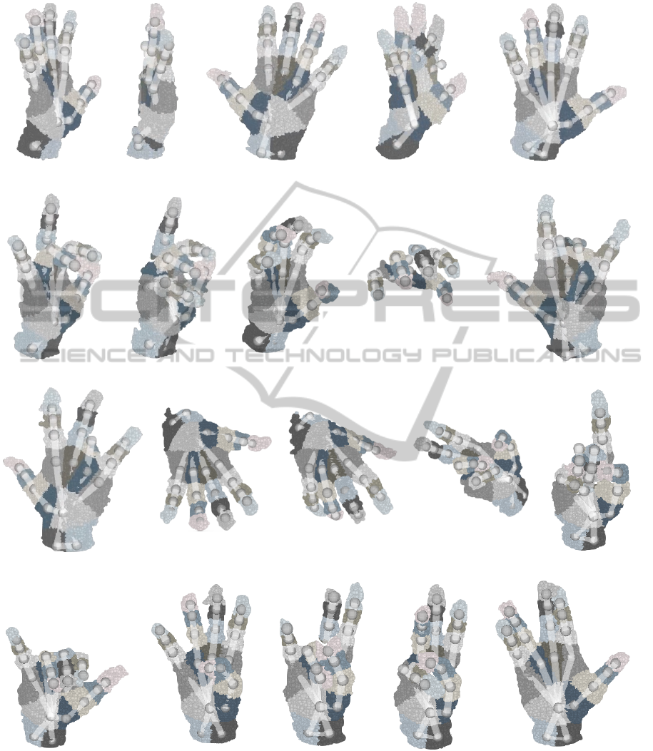
Some determined hand poses, while turning the
open hand, are given by the first row of Figure 4. The
approach allows to handle vertical rotations, whereas
some incorrect tracking results occur while rotating
the hand back (see Figure 4(d)). They are compen-
sated when the initial pose, where the palm faces the
camera, is reached. Figure 4(f)-(i) emphasize that
partial self-occlusions, caused by configurations us-
ing sharp angles in between the palm of the hand and
the camera, can be handled. Even poses while the
back of the hand faces the camera or the hand is ro-
tated in an arbitrary direction are estimated correctly
and illustrated in Figure 4(j)-(n). Furthermore, the ap-
proach allows to adapt the model on gesture-specific
hand configurations as shown in Figure 4(o)-(q). The
model is also able to track gestures where some fin-
gers are mostly parallel like the IML or the IMR ges-
tures (see Figure 4(r) and Figure 4(s)). Qualitative
tests show that the implemented gesture classifier is
able to distinguish the 29 trained gestures. Even sim-
ilar finger configurations like the open hand and the
so called vulcanian greeting shown in Figure 4(e) and
Figure 4(t) can be classified.
(a) (b) (c) (d) (e)
(f) (g) (h) (i) (j)
(k) (l) (m) (n) (o)
(p) (q) (r) (s) (t)
Figure 4: Determined hand skeleton model configurations with corresponding hand data. The first row shows some steps
during the vertical rotation of the open hand of 180
◦
and back. (f) - (i): The determined hand model in situations where there
is a sharp angle between the camera and the hand’s palm. (j) - (n): The pose can be tracked during arbitrary rotations and even
when the back of the hand faces the camera. (o) - (t) show the model while presenting the gestures I, TL, IMRL, IML, IMR,
and the so called vulcanian greeting. The priorly trained SVM is able to classify these gestures correctly.

5 CONCLUSION
In this paper, a real-time self-scaling kinematic hand
skeleton model based approach for full hand-finger
pose estimation while determining hand and finger
joints’ angles was presented. The model was itera-
tively adapted on the 3D data of the hand delivered by
a depth camera using a least-squares optimization ap-
proach. Therefore, the data-model distance was sim-
plified allowing the whole pose estimation process
to be done in an optimization process without prior
steps. Further, the model was equipped with a self-
scaling ability to handle different hand sizes automat-
ically.
A detailed evaluation of the approach was given
including quantitative and qualitative results. It was
shown that the approach allows to track the hand’s
skeleton under hard conditions such as turning the
hand and presenting complex finger gestures. Fur-
thermore, the tracking performance on standard hard-
ware without using the GPU is up to 30 FPS, limited
by the camera’s speed. In addition, there are no train-
ing data or prior calculations required. Thus, the pre-
sented method is more efficient than most of the other
known hand-finger tracking approaches.
Future work will focus on the remaining problems
like handling very fast hand or finger movements and
adaptable hand proportions. Some improvements on
the support vector machine based gesture classifier
and a quantitative evaluation are planned. In addition,
an extension of the presented approach to estimating
the arm pose or even the full body pose is intended.
This would enable human robot interaction applica-
tions like controlling an industrial robot or a robotic
hand and could be used for a simple teach-in proce-
dure. Even simultaneous tracking of both hands and
the body is planned.
REFERENCES
Aristidou, A. and Lasenby, J. (2010). Motion Capture
with Constrained Inverse Kinematics for Real-Time
Hand Tracking. In International Symposium on Com-
munications, Control and Signal Processing, number
March, pages 3–5.
Athitsos, V. and Sclaroff, S. (2003). Estimating 3D hand
pose from a cluttered image. 2003 IEEE Computer
Society Conference on Computer Vision and Pattern
Recognition 2003 Proceedings, 2:II–432–9.
Ballan, L., Taneja, A., Gall, J., Gool, L. V., and Pollefeys,
M. (2012). Motion Capture of Hands in Action Us-
ing Discriminative Salient Points. In Fitzgibbon, A.,
Lazebnik, S., Perona, P., Sato, Y., and Schmid, C., ed-
itors, Computer Vision – ECCV 2012, volume 7577 of
Lecture Notes in Computer Science, pages 640–653.
Springer.
ElKoura, G. and Singh, K. (2003). Handrix: animating the
human hand. Eurographics symposium on Computer
animation.
Erol, A., Bebis, G., Nicolescu, M., Boyle, R. D., and
Twombly, X. (2007). Vision-based hand pose estima-
tion: A review. Computer Vision and Image Under-
standing, 108(1-2):52–73.
Gorce, M. D. L., Fleet, D. J., and Paragios, N. (2011).
Model-Based 3D Hand Pose Estimation from Monoc-
ular Video. In IEEE Transactions on Pattern Analysis
and Machine Intelligence, volume 33, pages 1793–
1805. Laboratoire MAS, Ecole Centrale de Paris,
Chatenay-Malabry, IEEE.
Han, J., Shao, L., Xu, D., and Shotton, J. (2013). Enhanced
computer vision with Microsoft Kinect sensor: a re-
view. IEEE transactions on cybernetics, 43(5):1318–
34.
Horaud, R., Forbes, F., Yguel, M., Dewaele, G., and Zhang,
J. (2011). Rigid and articulated point registration with
expectation conditional maximization. IEEE Trans-
actions on Pattern Analysis and Machine Intelligence,
33(3):587–602.
Keskin, C., , Kirac, F., Kara, Y. E., and Akarun, L. (2011).
Real time hand pose estimation using depth sensors.
In Computer Vision Workshops (ICCV Workshops),
2011 IEEE International Conference on, pages 1228–
1234.
Keskin, C., , Kirac, F., Kara, Y. E., and Akarun, L. (2012).
Hand Pose Estimation and Hand Shape Classification
Using Multi-layered Randomized Decision Forests,
volume 7577. Springer Berlin Heidelberg.
Lee, J. and Kunii, T. (1995). Model-based analysis of hand
posture. Computer Graphics and Applications, IEEE,
15(5):77–86.
Liang, H., Yuan, J., and Thalmann, D. (2012). Hand Pose
Estimation by Combining Fingertip Tracking and Ar-
ticulated ICP. In Proceedings of the 11th ACM SIG-
GRAPH International Conference on Virtual-Reality
Continuum and Its Applications in Industry, VRCAI
’12, pages 87–90, New York, NY, USA. ACM.
Oikonomidis, I., Kyriazis, N., and Argyros, A. (2011). Ef-
ficient model-based 3D tracking of hand articulations
using Kinect. Procedings of the British Machine Vi-
sion Conference, pages 101.1–101.11.
Oikonomidis, I., Kyriazis, N., and Argyros, A. A. (2010).
Markerless and Efficient 26-DOF Hand Pose Recov-
ery. Hand The, pages 744–757.
Qian, C., Sun, X., Wei, Y., Tang, X., and Sun, J. (2014).
Realtime and Robust Hand Tracking from Depth. In
IEEComputer Vision and Pattern Recognition.
Raheja, J. L., Chaudhary, A., and Singal, K. (2011). Track-
ing of Fingertips and Centers of Palm Using KINECT.
Third International Conference on Computational In-
telligence Modelling Simulation, pages 248–252.
Ren, Z., Meng, J., and Yuan, J. (2011). Depth Camera
Based Hand Gesture Recognition and its Applications
in Human-Computer-Interaction. IEEE International

Conference on Information Communication and Sig-
nal Processing, (1):3–7.
Ren, Z. and Yuan, J. (2011). Robust hand gesture recog-
nition based on finger-earth mover’s distance with a
commodity depth camera. Proceedings of the 19th
ACM international, pages 1–4.
Schr
¨
oder, M., Elbrechter, C., Maycock, J., Haschke, R.,
Botsch, M., and Ritter, H. (2012). Real-Time Hand
Tracking with a Color Glove for the Actuation of An-
thropomorphic Robot Hands. In Proceedings of IEEE-
RAS International Conference on Humanoid Robots,
pages 262–269.
Schr
¨
oder, M., Maycock, J., Ritter, H., and Botsch, M.
(2013). Analysis of Hand Synergies for Inverse Kine-
matics Hand Tracking. In IEEE International Con-
ference on Robotics and Automation, Workshop of
”Hand synergies - how to tame the complexity of
grasping”.
Shotton, J., Fitzgibbon, A., Cook, M., Sharp, T., Finocchio,
M., Moore, R., Kipman, A., and Blake, A. (2011).
Real-time human pose recognition in parts from single
depth images. IEEE Conference on Computer Vision
and Pattern Recognition, pages 1297–1304.
Sridhar, S., Oulasvirta, A., and Theobalt, C. (2013). Inter-
active Markerless Articulated Hand Motion Tracking
Using RGB and Depth Data. 2013 IEEE International
Conference on Computer Vision, pages 2456–2463.
Wang, R., Paris, S., and Popovi
´
c, J. (2011). 6D Hands:
Markerless Hand-tracking for Computer Aided De-
sign. In Proceedings of the 24th Annual ACM Sym-
posium on User Interface Software and Technology,
UIST ’11, pages 549–558, New York, NY, USA.
ACM.
Wang, R. Y. and Popovi
´
c, J. (2009). Real-time hand-
tracking with a color glove. ACM Transactions on
Graphics, 28(3):1.
Wang, Y., Min, J., Zhang, J., Liu, Y., Xu, F., Dai, Q., and
Chai, J. (2013). Video-based hand manipulation cap-
ture through composite motion control. ACM Trans-
actions on Graphics, 32(4):1.
Zhao, W., Zhang, J., Min, J., and Chai, J. (2013). Robust re-
altime physics-based motion control for human grasp-
ing. ACM Transactions on Graphics, 32(6):1–12.
