
Procedural Animation of Human Interaction
using Inverse Kinematics and Fuzzy Logic
Gaetan Deglorie
1
, Koen Samyn
2
, Peter Lambert
1
, Rik Van de Walle
1
and Sofie Van Hoecke
1
1
ELIS Department, Multimedia Lab, Ghent University-iMinds, Gaston Crommenlaan 8, Bus 201, B-9050 Gent, Belgium
2
DAE, University College West Flanders, Ghent University Association, Botenkopersstraat 2, 8500 Kortrijk, Belgium
Keywords:
Procedural Animation, Multi-character Interaction, Inverse Kinematics, Fuzzy Logic.
Abstract:
Nowadays, animation of human interaction is predominantly modelled statically. Animations are adapted
manually to each set of participating characters to ensure visual fidelity. To automate this process, we propose
a novel procedural animation technique where character interactions are modelled dynamically with fuzzy
logic and compare our technique to conventional inverse kinematics. The ’handshake’ interaction is used as
an example interaction, in order to illustrate how basic animation rules are defined, while leaving room for
parametrization of character specific properties. Our results show that, although inverse kinematics delivers
higher precision in positioning than fuzzy logic, they are dependent on paths describing the motion of the final
element in the kinematic chain. Fuzzy logic, on the other hand, is independent of such motion paths and solves
towards the target location locally. The presented handshake model using fuzzy logic can serve as a basis for
future models for virtual-human interaction.
1 INTRODUCTION
Video games, movies and simulations often contain
scenes with character interaction. To create anima-
tions for these interactions, a large fraction of pro-
duction resources is spent on manually producing or
recording these animations through motion capture.
Although the resulting animations do not adapt at
runtime without extra processing steps, this property
is highly desirable in dynamic virtual environments.
One approach towards adaptive animation is procedu-
ral animation, where animations are generated algo-
rithmically. Two important problems exist for this ap-
proach: (1) synchronization of separate animation se-
quences of participating characters, and (2) real-time
synthesis in order to generate animations for a specific
context in a real-time environment.
In this paper, we compare two procedural anima-
tion techniques for animating human interactions:
1. inverse kinematics, where limbs are retargeted
based on joint parameters obtained from kine-
matic equations (Johansen, 2009)
2. fuzzy logic controllers, where the joint parameters
are locally controlled for each joint (Samyn et al.,
2012).
Both procedural animation approaches are compared
using a handshake test case.
The remainder of this paper is as follows. After
an overview of related work in Section 2, the method-
ology of our approach is presented in Section 3. Sec-
tion 4 describes a case study of real-life handshakes,
as well as the concluded rules for defining the virtual
model. Next, in Section 5, the underlying framework
facilitating animations of human interactions is pre-
sented. In Section 6 the model of the handshake is
described in detail. The results are presented in Sec-
tion 7. Finally, the conclusions and future work are
summarised in Section 8.
2 RELATED WORK
In this section, the state-of-the-art on procedural
animation and multi-character animation is reviewed.
Procedural Animation
Multiple variants of procedural animation exist; we
list the ones most relevant to our work.
First, animation retargeting adapts an existing an-
imation to a new context or situation. E.g., the walk
cycle of a character on a flat surface can be adapted to
slanted surfaces. This technique can be implemented
using inverse kinematics (Johansen, 2009).
340
Deglorie G., Samyn K., Lambert P., Van de Walle R. and Van Hoecke S..
Procedural Animation of Human Interaction using Inverse Kinematics and Fuzzy Logic.
DOI: 10.5220/0005310603400347
In Proceedings of the 10th International Conference on Computer Graphics Theory and Applications (GRAPP-2015), pages 340-347
ISBN: 978-989-758-087-1
Copyright
c
2015 SCITEPRESS (Science and Technology Publications, Lda.)

Second, physics-based character animation uti-
lizes real-time physics simulation to animate the
limbs of articulated skeletons. This way, high visual
fidelity is achieved, but the animations lack the high
level of control that is required by traditional anima-
tion artists (Geijtenbeek and Pronost, 2012).
Finally, a third approach procedurally animates
the walk cycle of a character using fuzzy logic
controllers (Samyn et al., 2012). In this paper we
extend this approach to be usable for multi-character
animation.
Multi-character Animation
The creation of animation for multi-character interac-
tions has been approached in literature in a number of
ways.
First, a combined physics-based and data-driven
approach creates multi-character motions from short
single-character sequences (Liu et al., 2006) and de-
fines the motion synthesis as a spacetime optimisation
problem. This method animates the approach of two
hands towards each other, by iteratively drawing them
together until convergence is reached. However, this
solution is not suitable for real-time synthesis.
Secondly, Kwon models competitive interac-
tion (i.e. Taekwondo) as a dynamic Bayesian net-
work (Kwon et al., 2008). It synchronizes the ani-
mation of multiple characters by timewarping the ap-
propriate sequences of motion capture data. Whereas
Kwon uses multi-character motion capture, Schum
uses motion capture data of a single person (Shum
et al., 2012). Here character interactions are simu-
lated by expanding a game tree of possible states and
evaluating these states towards the future to select the
appropriate animation sequence. Both approaches are
unable to adapt their respective animations to differ-
ent character configurations.
A novel Laplacian motion editing method lets
artists manipulate synchronized multi-character an-
imation through the use of synchronized motion
paths (Kim et al., 2009). These motion paths de-
scribe the position of the character in space and time,
while constraint-based displacement is used to con-
strain specified limbs to a target location (e.g., char-
acters’ hands constraints when carrying a chair).
to achieve synchronization, adaptation and real-
time synthesis.
3 METHODOLOGY
The state-of-the-art approaches to animate multi-
ple characters mostly address issues concerning syn-
chronization of individual animations and adaptation
through motion re-targeting. They however do not
deal with real-time synthesis, which will become a
necessity with the ever increasing variation of charac-
ters in virtual environments. To solve this shortcom-
ing, a novel procedural animation technique based on
fuzzy logic is presented to achieve synchronization,
adaptation and real-time synthesis.
We compare this fuzzy logic based techniques to
create multi-character animation using parametriza-
tion of procedural techniques with inverse kinematics
(IK). Whereas conventional IK is used to retarget ex-
isting animations (Johansen, 2009), we use it to retar-
get kinematic chains (i.e. the right arms of the charac-
ters) to keyframed motion paths in order to overcome
the need for captured data. The IK controller calcu-
lates the joint parameters of the kinematic chain for
each frame, based on the current path position. Con-
trary to IK, the fuzzy logic approach solves towards
the target location locally (i.e. considering joints in-
dependently) in incremental time steps and allows the
use of both motion paths and static targets.
Our method supports synchronization and adapta-
tion. To create believable animations of human inter-
actions, the individual animations of each character
have to be synchronized. By constraining the end ef-
fectors (i.e. final joint in a kinematic chain) of mul-
tiple characters to the same motion path, they per-
form synchronized animations. The animation adapts
to all partaking characters by parametrizing the mo-
tion paths and/or targets, specifically to their position,
dimensions and personality (i.e. dominance).
4 CASE STUDY
Our animation model is based on a two-part case
study that captured handshake gestures between pairs
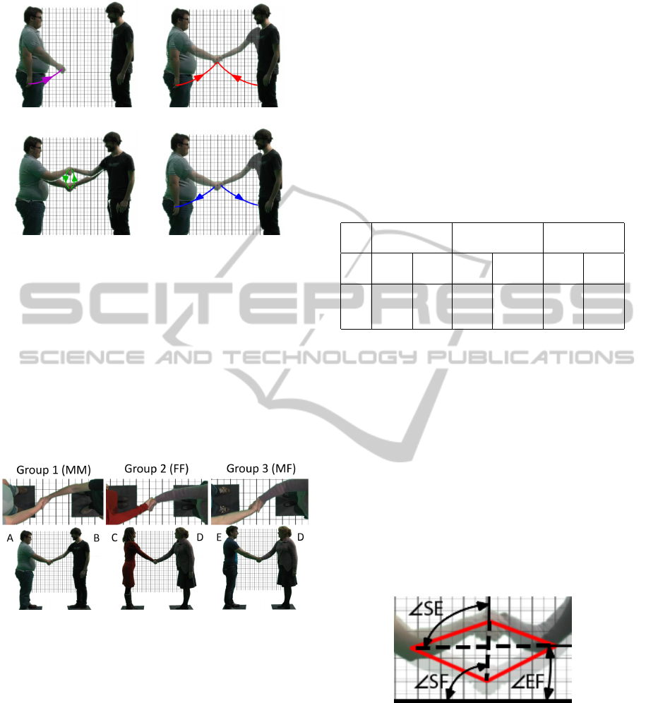
of people. We identify four phases within the hand-
shake interaction: dummy phase (the starting subject
invites the other subject to shake hands), approach
phase (both hands move towards each other to initiate
the grip), shake phase (the hands move up and down)
and retreat phase (the subjects retract their hands back
towards their body). The different phases are dis-
played in Figure 1.
In the case study, we focus on the shake phase, ex-
amining the flow and dimensions of the shaking mo-
tion and the orientation of the hands during the hand
grip in particular.
4.1 Shaking Motion of the Hands
The test used five test subjects (named A-B-C-D-E),
paired into three groups: (1) male A - male B, (2) fe-
ProceduralAnimationofHumanInteractionusingInverseKinematicsandFuzzyLogic
341
(a) Dummy (b) Approach
(c) Shake (d) Retreat
Figure 1: The subsequent phases of the handshake.
male C - female D, and (3) male E - female D. The
handshake was performed five times by each group to
mitigate the effect of possible outliers in the captured
data. While performing the handshake experiments,
the subjects stood on pre-placed markers so that the
data on the arm movements could be compared. The
shake phase of each handshake was analysed using a
top and a side view (see Figure 2). We refer to the
starting point of the shake phase as the “point of con-
tact”.
Figure 2: Stills of the 3 groups during part one of the case
study.
Considering the overall flow, we observed both
single-shake (group 1) and multi-shake (groups 2 and
3) interaction. In the latter two groups, the multiple
shakes can be separated as one large primary shake
and multiple smaller secondary shakes. These sec-
ondary shakes can be accredited to subject D. We only
focus here on the primary shake.
The video footage used for this part of the case
study can be found at http://vimeo.com/107897073.
4.1.1 Top View Analysis
During analysis of the top view, we observed two
characteristics. First, during the shake phase the
joined hands stay in line with both (right) elbows,
i.e. the handshake grip and elbows create an initial
plane perpendicular to the floor, in which the entire
shake phase occurs. Second, on average the point
of contact is centred in between the subjects. Slight
deviations can occur as a result of difference in arm
length (group male-male), subject position or dom-
inance between subjects. We infer dominance of a
person from the rule that a dominant person keeps
the shake away from his/her personal space (Lewis,
2012).
Table 1: Results of angle analysis for the 3 groups.
Group 1 Group 2 Group 3
male-male female-female male-female
Avg. Std. Avg. Std. Avg. Std.
Dev. Dev. Dev.
EF 3.2 1.2 0.5 3.0 3.9 2.2
SF 92.5 2.9 77.2 11.5 86.2 3.5
SE 89.4 2.2 76.7 14.2 82.3 3.9
4.1.2 Side View Analysis
The vector of travel for both hands was also stud-
ied, i.e. the direction and distance travelled during
the shake phase, referred to as “shake direction” and
“shake distance” respectively. To infer both, we used
the video frames corresponding to the lowest and
highest position during the shake phase. By over-
laying these frames, the figure can be simplified as
a quadrilateral (as represented in Figure 3). We ob-
served that in some cases the elbow moves between
the lowest and highest position. In that case, we
used the position of the lowest point to construct the
quadrilateral. Next, we determined the orientations
Figure 3: Side view handshake of group 3 with highlights.
of the diagonals (indicated by the dashed lines). The
horizontal diagonal is referred to as the elbow-line
and the vertical diagonal as the shake-line. We ob-
serve three angles (illustrated in Figure 3): (1) be-
tween the elbow-line and the floor (EF), (2) between
the shake-line and the floor (SF), and (3) between the
shake-line and the elbow-line (SE). As can be seen in
Table 1, EF is always close to zero. Deviations can be
explained by either the difference in height (e.g. for
GRAPP2015-InternationalConferenceonComputerGraphicsTheoryandApplications
342
group 1) or a result of the personalities of the sub-
jects. The results of group 1 show that SE should be a
right angle. In the cases of group 2 and 3, we attribute
the deviations from this value to an implied difference
in mannerism. SF is the superposition of angles SE
and EF. For the direction of travel during the shake
phase, we use SE and constrain it to be a right angle
(i.e. shake-line perpendicular the elbow-line).
The shake distance is calculated as a proportion
of the elbow-line length. No large deviations are
observed for this proportion. On average across all
cases, the final ratio of shake distance to distance be-
tween elbows is 35 percent. This value is used as an
input for the generation of the vector of travel during
the shake phase, i.e. the observed effect in the result-
ing animation. More detail is given in Section 7.
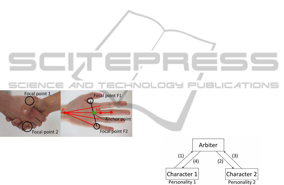
4.2 Orientation of the Hands
Next, we define the specific orientation and positional
offset required to model a handshake grip. In our
model both hands are assumed equal in size. To
Figure 4: Handshake grip with focal points (left) and single
hand analysis (right).
model the handshake grip, two focal points are iden-
tified. As can be seen on Figure 4, these focal points
on each hand coincide with the matching focal points
of the other hand and are aligned vertically during the
grip. The intersection of the line between the focal
points and the middle finger palm bone (i.e. third
metacarpal bone) serves as the center of rotation, in-
dicated by the “anchor point” square. The angle of
rotation is defined as the required rotation to place
line F1-F2 in a vertical position. Next, a small offset
reduces the implicit clipping behaviour of both hands.
This offset is defined as half the thickness of the palm,
in the direction of the normal vector leaving the palm.
4.3 Complete Handshake Model
Based on the case study of real life handshakes, a set
of rules is created for defining a virtual handshake
model. These rules consist of:
1. the initial point of contact of both hands located
between the subjects (weighted according to dom-
inance);
2. the vector of travel of the shake phase (35 percent
of the distance between the elbows; in the direc-
tion perpendicular to the elbow-line); and
3. the orientation and offset of the hands during
the shake phase (based on the dimensions of the
hand).
5 FRAMEWORK
Based on the handshake case study, a framework for
the creation and playback of interaction animations is
designed.
We personify virtual humans through personal-
ity traits represented by key-value pairs (trait name
- trait value). Traits such as dominance can be spec-
ified and compared in order to adapt animations ac-
cordingly. We parametrize the handshake animation
model through the personality trait of dominance.
A handshake is an example of an interaction
where one subject starts the interaction and the other
subject accepts (or refuses) this initiation. The ani-
mation framework should therefore support interac-
tions with an asynchronous start. Accordingly, an ar-
biter component is introduced (see Figure 5) in order
to support this behaviour while doubling as a skeletal
pose sharing service. For reusability, the arbiter is de-
signed to be animation- and controller type agnostic.
Figure 5: Interaction work flow with arbiter.
The arbiter handles the asynchronous start and
shares information between both parties (more specif-
ically sharing the current skeletal pose of the other
subject). If the interaction is accepted, the arbiter
passes a reference to the data of each subject to the
other. The architecture of the arbiter is completely in-
dependent of the handshake animation and controller
type, allowing the arbiter to be used in future for other
similar types of animation (e.g. high fives).
6 HANDSHAKE ANIMATION
We now show how to implement the handshake in-
teraction in our framework. We describe the motion
of the hands using the four handshake phases defined
ProceduralAnimationofHumanInteractionusingInverseKinematicsandFuzzyLogic
343
in Section 4: dummy, approach, shake and retreat.
The initiating character starts with the dummy phase,
here the hand moves a short distance in front of the
character. Next, both characters go into the approach
phase, moving the hands from a neutral position (or
current position for the initiating subject) to the point
of contact. The shake phase then, calculates the vec-
tor of travel and moves the hands upward and down-
ward along this vector. During this phase, the motion
of both hands is synchronized using a shared motion
path. Furthermore, a geometric handle is used to en-
force rotation and offset of both hands. Finally, the
retreat phase makes the hands return to a neutral po-
sition or an ongoing overarching animation.
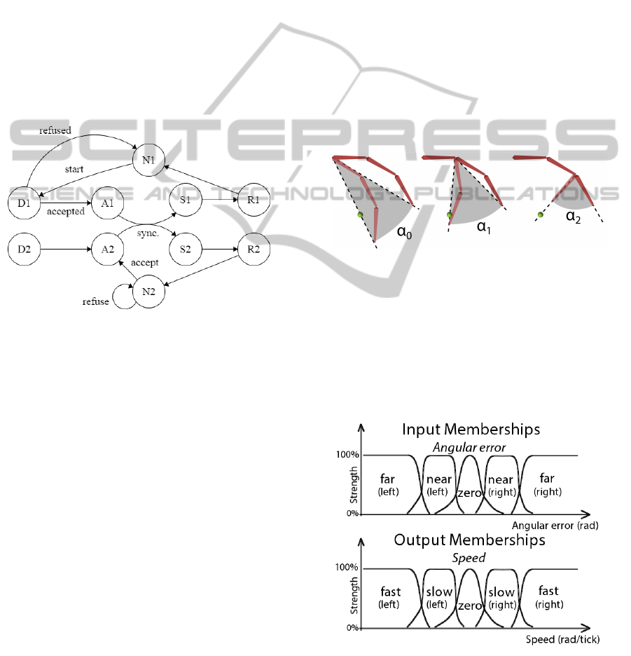
The transitions between phases are modelled as
a finite state machine (FSM) as shown in Figure 6.
State transitions are handled individually with the ex-
Figure 6: Handshake phases modelled as a finite state ma-
chine with states: N1 (neutral state of initiating subject),
N2 (neutral state of other subject), D (dummy phase), A
(approach phase), S (shake phase) and R (retreate phase).
ception of the transition from A1/A2 to S1/S2 where
both parties need to agree (i.e. synchronize) in order
to switch states.
For every phase, each character initializes a par-
tial animation and adapts it according to the position,
dimensions and personality of the character. As par-
tial animations are initialized right before the start of
each phase, the animation can adapt to parametrical
or environmental changes on a per-phase granularity.
In the following subsections, we discuss the use of
IK and fuzzy logic animation controllers in the frame-
work.
6.1 Inverse Kinematics
Our IK approach uses keyframed motion paths to
guide the character animation, i.e. the end effector
of the kinematic chain moves along this path. The
motion paths are represented by B-splines, facilitat-
ing personalisation of the animation. The path is con-
structed as the shortest distance between two points:
the current location of the hand and the target loca-
tion for the end of that phase (e.g. the point of contact
defines the end of the approach phase).
IK has many known implementations (Aristidou
and Lasenby, 2009), two of the more popular being
Jacobian Transpose IK and Cyclic Coordinate De-
scent IK (CCD). Both alternatives are compared in
Section 7.
6.2 Fuzzy Logic
In the fuzzy logic approach, a fuzzy logic controller
is attached to each individual joint of the kinematic
chain. The input of the fuzzy logic controllers is an-
gular error α
i
. Angular error is determined locally
for each joint, and is defined by the rotation required
to move the end effector in line with the target posi-
tion (see Figure 7). We let the joint angles approach
Figure 7: Angular error α
i
of each joint in the kinematic
chain.
their target state at a speed that scales with the an-
gular error of their respective joint. Conceptually,
both the input and output have five membership func-
tions (Zadeh and Kacprzyk, 1992). Angular error has
memberships: Far(left), Near(left), Zero, Near(right)
and Far(right); speed has memberships: Fast(left),
Slow(left), Zero, Slow(right) and Fast(right).
Figure 8: Input and output memberships for the fuzzy logic
controllers.
GRAPP2015-InternationalConferenceonComputerGraphicsTheoryandApplications
344

We use the following rules for each controller:
IF angularError IS FarL THEN speed IS FastR
IF angularError IS CloseL THEN speed IS SlowR
IF angularError IS Zero THEN speed IS Zero
IF angularError IS CloseR THEN speed IS SlowL
IF angularError IS FarR THEN speed IS FastL
From this, the controller returns a fuzzy output for
the speed of the joint. The output is defuzzified us-
ing a centroid defuzzifier to obtain the matching scalar
value for the speed. By keeping the output values for
speed low, all joints rotate in small increments over
time.
Hence, it is possible to animate using only a static
target position, instead of requiring motion paths as
was the case with IK.
The animator has no exact control over the path
taken by the end effector towards such static target
positions. If however control is wanted, the animator
can choose to use motion paths instead.
By adding rotational information to the target po-
sition, we can extend our approach to support axial
rotation of the individual bones, which in turn can re-
duce artefacts during transitions between phases.
7 RESULTS
The handshake animation can be configured in two
important ways, on one hand the choice of animation
controllers in both characters, and on the other hand
the influence of character properties such as position,
scale and personality. Video footage of all configura-
tions can be found on http://vimeo.com/107897074.
7.1 Animation Controller Configuration
We evaluated four test configurations for both anima-
tion controller independence and animation controller
performance.
Table 2: Four configurations of animation controllers.
# Controller 1 Controller 2
1 Jacobian Transpose Jacobian Transpose
2 CCD CCD
3 Fuzzy logic Fuzzy logic
4 CCD Fuzzy logic
For each test configuration, we evaluated the po-
sitional precision of the end effector or right hand of
each character during the shake phase. Three metrics
were calculated as a measure of error: (1) the distance
between both end effectors, (2) the distance between
the hand of character 1 and the target, and (3) the dis-
tance between the hand of character 2 and the target.
The resulting values are presented in Figure 9.
Note that distance is expressed in engine units, cor-
responding to centimetres in the real world.
The summarized results for all graphs are dis-
played in Table 3. For errors, we calculated both the
mean and the standard deviation. Execution times
are also shown as a measure of performance (mea-
sured as number of CPU ticks per frame on an In-
tel(R) Core(TM) i7-2600 3.40GHz).
Configuration 1 achieves an overall high accuracy
with only a small decrease halfway the animation, as
shown in Figure 9(a). However, this high level of pre-
cision comes at the cost of a comparatively higher ex-
ecution time (see Table 3).
Configuration 2 has an overall lower precision
than Jacobian Transpose with a comparatively better
precision halfway the shake (see Figure 9(b)). Ad-
ditionally, the video footage shows that the hands do
not maintain their relative alignment. This is due to
the iterative rotation of joints in CCD, which makes
the final bone in the chain align with the target. This
is particularly visible at the end of the approach phase
and start of the retreat phase.
Configuration 3 has both subjects using fuzzy
logic controllers. As can be seen in Figure 9(c) and
Table 3, the precision of this configuration has an
overall lower precision than with both IK methods.
The path of the gradient shows that fuzzy logic has
reactive behaviour. The error increases because it is
unable to keep up with the animation target. At the
peak of the shake phase, the target switches direction
and moves towards the delayed end-effector, decreas-
ing the error severely. After passing the end effec-
tor, the error increases again towards the end of the
shake phase. The complete error shows similar be-
haviour, which can be accredited to a small difference
in movement speed of both hands.
Configuration 4 shows the hybrid controller ap-
proach. The performance, shown in Figure 9(d), is
not surprisingly a superposition of the separate er-
ror rates. It shows how our underlying interaction
framework operates independently of specific anima-
tion controller types. To our knowledge, this is not
possible in the current state-of-the-art.
As can be seen in Table 3, Jacobian Transpose IK
(configuration 1) performs with the lowest error rate
in all cases, but at the expense of having the lowest
computational performance. CCD IK (configuration
2) has a slightly higher error rate, but has the best
performance of all. Fuzzy logic (configuration 3) of-
fers a tradeoff with an error rate that is higher than
CCD and a performance in between CCD and Jaco-
bian Transpose. The resulting precision of the hybrid
configuration (configuration 4) is an average between
ProceduralAnimationofHumanInteractionusingInverseKinematicsandFuzzyLogic
345
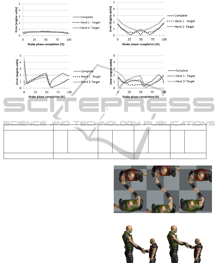
(a) Jacobian Tranpose (b) CCD
(c) Fuzzy logic (d) Hybrid (Hand 1:IK / Hand 2: Fuzzy logic)
Figure 9: Error measurement for each configuration.
Table 3: Summary of animation controller influence.
Configuration Jacob. Transpose(1) CCD(2) Fuzzy logic(3) Hybrid(4)
Error Avg. Std.Dev. Avg. Std.Dev. Avg. Std.Dev. Avg. Std.Dev.
Complete 0.53 0.10 0.72 0.46 1.70 0.61 1.14 0.40
Hand 1 0.58 0.05 0.73 0.40 1.13 0.56 0.78 0.37
Hand 2 0.50 0.06 1.35 0.55 1.06 0.57 1.09 0.57
Performance (ticks/fr.) 1250 300 800 N/A
fuzzy logic and CCD. We believe that the fuzzy logic
approach can reach similar precision as CCD in the
future. The fuzzy logic error curve shows delayed fol-
lowing behaviour, which can be reduced by tweaking
the controller response speed.
7.2 Character Configuration
We now discuss the adaptability of the animation to
changes in position, dimensions and personality. The
effect of changes in character position is presented in
Figure 10. As can be seen, the orientation and posi-
tion of the handshake adapts automatically according
to the model described in Section 4. However, as we
only animate from the clavicle to the hand, the current
model has a limited range of valid character positions.
Figure 11 shows the effect of scale difference. The
complete handshake automatically adapts to the scale,
except for the handshake grip. Again, the range of
possible scale differences is limited, as our human
model cannot bend over to shake hands with very
small characters.
Finally, in Figure 12 the effect of difference in per-
sonality is displayed. Both characters have a person-
ality trait “dominance” which influences the point of
Figure 10: Varying configurations of character position.
Figure 11: Variation of character scale.
contact. The handshake grip shifts towards the less
dominant character (the left character in this figure).
GRAPP2015-InternationalConferenceonComputerGraphicsTheoryandApplications
346
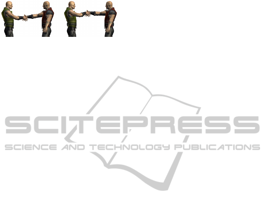
Figure 12: Variation of character personality.
8 CONCLUSION AND FUTURE
WORK
In this paper, we presented a handshake animation
model as a use case for general multi-character in-
teractions. The model synchronizes specific parts of
the animation in order to achieve believable inter-
actions, whilst adapting to changes in position, di-
mensions and personality of the participating charac-
ters. Compared to the current state-of-the-art, our ap-
proach synchronizes multiple single character anima-
tions and is suitable for real-time animation synthesis.
We compared inverse kinematics with fuzzy logic.
Whereas inverse kinematics achieves a higher preci-
sion than fuzzy logic, it however relies completely on
motion paths. Contrary, fuzzy logic can operate with-
out them. When using static targets with fuzzy logic,
the animator cannot control the path taken by the end
effector towards these targets. In that case motion
paths can still be used to enforce a certain path.
Both presented approaches use motion paths to
facilitate synchronization in an animation controller
type agnostic manner. This enables us to create hy-
brid interactions where both characters use different
animation controller types.
Future work can encompass, on one hand, creating
alternative animations to handshakes and, on the other
hand, increasing the detail of this interaction model.
For fuzzy logic, future work can be the use of ma-
chine learning to tweak the individual controllers, the
addition of axial rotation control to the end effector,
and handling of non-constant speed values throughout
the phases. Furthermore, more in depth case studies
should be done in order to achieve animations with
higher (visual) fidelity.
ACKNOWLEDGEMENTS
The authors would like to thank DigitalRune GmbH
for providing a non-commercial license of their li-
brary. This work was partly funded by the Friendly
Attac project (http://www.friendlyattac.be/), a project
of the Institute for the Promotion of Innovation
through Science and Technology in Flanders (IWT).
REFERENCES
Aristidou, A. and Lasenby, J. (2009). Inverse kinematics:
a review of existing techniques and introduction of a
new fast iterative solver.
Geijtenbeek, T. and Pronost, N. (2012). Interactive charac-
ter animation using simulated physics: A state-of-the-
art review. In Computer Graphics Forum, volume 31,
pages 2492–2515. Wiley Online Library.
Johansen, R. S. (2009). Automated semi-procedural an-
imation for character locomotion. Master’s thesis,
Aarhus University, Department of Information and
Media Studies.
Kim, M., Hyun, K., Kim, J., and Lee, J. (2009). Syn-
chronized multi-character motion editing. In ACM
Transactions on Graphics (TOG), volume 28, page 79.
ACM.
Kwon, T., Cho, Y.-S., Park, S. I., and Shin, S. Y. (2008).
Two-character motion analysis and synthesis. Visu-
alization and Computer Graphics, IEEE Transactions
on, 14(3):707–720.
Lewis, H. (2012). Body language: A guide for profession-
als. SAGE Publications India.
Liu, C. K., Hertzmann, A., and Popovi
´
c, Z. (2006).
Composition of complex optimal multi-character mo-
tions. In Proceedings of the 2006 ACM SIG-
GRAPH/Eurographics symposium on Computer ani-
mation, pages 215–222. Eurographics Association.
Samyn, K., Van Hoecke, S., Pieters, B., Hollemeersch, C.,
Demeulemeester, A., and van de Walle, R. (2012).
Real-time animation of human characters with fuzzy
controllers. In Proceedings of The 2012 Computer
Graphics International Conference. Computer Graph-
ics Society.
Shum, H. P. H., Komura, T., and Yamazaki, S. (2012). Sim-
ulating multiple character interactions with collabo-
rative and adversarial goals. Visualization and Com-
puter Graphics, IEEE Transactions on, 18(5):741–
752.
Zadeh, L. and Kacprzyk, J. (1992). Fuzzy logic for the man-
agement of uncertainty. Wiley professional comput-
ing. Wiley.
ProceduralAnimationofHumanInteractionusingInverseKinematicsandFuzzyLogic
347
