
Specification of Decision-making and Control Flow Branching in
Topological Functioning Models of Systems
Erika Asnina and Viktoria Ovchinnikova
Department of Applied Computer Science, Riga Technical University, Meza Str. 1 – k.3, Riga, Latvia
Keywords: Logical Relations, Branching, Decision Model, Topological Functioning Model, Domain Modelling.
Abstract: System behaviour usually is modelled with logical operators and triggering conditions on control flows
between processes, activities, tasks, or events. This allows branching control flows in order to increase
model comprehensibility. In case of Topological Functioning Model (TFM), where system’s functionality is
represented by causal relations among functional characteristics, combinations of causes as well as triggered
effects may be quite complex. Therefore, specification of them must not decrease apprehensibility of the
TFM, while keeping its accuracy, compactness and level of abstraction. Additionally, this specification must
also be modifiable and transformable. In this paper we discuss and refine a concept of a cause-and-effect
relation and a logical relation in the TFM. Then, we analyze specification means used in BPMN, UML
Activity Diagrams, EPCs, flowcharts, Petri Nets and Decision Models and assess which of them are more
appropriate for using or integrating with the TFM. The more suitable means will increase the accuracy of
specification of logical relations and system behaviour in the TFM. As a result, it would be possible to
eliminate human participation in transformations from the TFM to models at the lower level of abstraction.
1 INTRODUCTION
Business rules usually are represented as logical
relations and conditions that drive control flows in
business processes. We discuss ways of specifying
business rules for decision making in behavioural
models, namely using BPMN, UML Activity
Diagrams, EPCs, flowcharts, Petri Nets, and
Decision Models. The aim of the paper is to find out
the suitable specification mechanism of logical
relations in the Topological Functioning Model
(TFM).
The TFM represents system’s functionality as
functional characteristics and a set of binary causal
dependencies among them. The causal dependencies
form cause and effect topology on the set of
functional characteristics of the system. In other
words, functionality of the system is described as
chains and cycles of causes and effects. A more
detailed explanation is represented in Section 2.
The issue is that initially this model was applied
for diagnostics of mechanical systems. It lacks a
mechanism for representation of logical conditions
on causal dependencies. At the present, we apply the
TFM for software development in the context of
Model Driven Development (MDD). It serves as a
computation independent model of systems such as
an organization, an information system, or software.
Mainly, we apply it as a kind of a business/domain
model, which is a root model for further
transformations to more detailed models. Logical
relations of causal dependencies in the TFM is a
decision-making and branching mechanism. This
mechanism is necessary for getting branches of
control flows in UML models (or other models of
interactions or processing) derived from the TFM.
Therefore, specification of this mechanism became
very significant. This may enhance a number of
elements of the TFM. However, the mathematical
formalism, system theoretical foundations and
simplicity are three key characteristics of this model,
and any additional elements must keep them also in
further.
The paper is structured as follows. Section 2
represents main concepts of the TFM and its
application within MDD. Section 3 illustrates an
assessment of suitability of specification means for
decision-making and branching in process-oriented
models of the systems. Conclusions analyze the
obtained results and indicate directions of further
research on this topic.
364
Asnina E. and Ovchinnikova V..
Specification of Decision-making and Control Flow Branching in Topological Functioning Models of Systems.
DOI: 10.5220/0005479903640373
In Proceedings of the 10th International Conference on Evaluation of Novel Approaches to Software Engineering (MDI4SE-2015), pages 364-373
ISBN: 978-989-758-100-7
Copyright
c
2015 SCITEPRESS (Science and Technology Publications, Lda.)

2 TFM FOR MDD
The Topological Functioning Model (TFM) was
introduced and described by Janis Osis in (Osis,
1969), (Osis, 1972). Since 1970s this model was
applied for development of high-quality diagnostic
algorithms and methods as well as system modelling
and analysis in medicine. At the end of the 20
th
century, research on application of this model for
system modelling and analysis in object oriented
software development and MDD begun (Osis and
Asnina, 2011-a). In the context of Model Driven
Architecture (MDA) proposed by OMG (Mukerji
and Miller, 2003) the TFM is used as a computation
independent source model for its further
transformations to the platform independent and
platform specific models specified in Unified
Modeling Language (UML). Thanks to its holistic
and formal nature, the TFM is a formal base for
verification of requirements completeness (Osis, et
al., 2008), determination of shared functionality and
derivation of use cases (Osis and Asnina, 2011-d),
transformation to UML diagrams and TopUML
diagrams in order to derive the system structure
(Donins, et al., 2011), (Donins, 2012), (Osis, et al.,
2014), and integration of system knowledge that
usually are expressed as a set of interrelated
fragments (Slihte, et al., 2011), (Slihte and Osis,
2014).
2.1 Foundations of the TFM
The TFM can be characterized as an engineering
model by using key characteristics defined by Bran
Selic (Selic, 2003), namely it has abstract,
understandable, accurate, predictive and inexpensive
nature.
It has two construction elements, namely a
functional characteristic of the system called a
functional feature and a cause-and-effect relation
that shows topological causal dependency (or
relation) between two functional features.
The TFM is based on principles of algebraic
topology and system theory. Mathematically, the
TFM is represented in the form of a topological
space (X, ), where X is a finite set of functional
features (characteristics) of the system under
consideration, and is the topology that satisfies
axioms of topological structures (Osis, 1969).
Visually it is represented in the form of a directed
graph.
A functional feature is defined as a 7-tuple <A,
R, O, PrCond, PostCond, Pr, Ex>, where:
A is an action linked with a domain object;
R is a result of that action (it is an optional
element); it could be a domain object or a set
of them, a message, a trigger for the effect
event etc.;
O is a domain object that gets the result of the
action or a set O of domain objects which are
used in this action (in case when an item of Ex
gets result R); it could be a role, a time period
or a moment, catalogues etc.;
PrCond is a set PrCond = {prec
1
, …, prec
i
},
where prec
i
is a precondition or an atomic
business rule (it is an optional element) of the
action;
PostCond is a set PostCond = {postc
1
, …,
postc
i
}, where postc
i
is a post-condition or an
atomic business rule (it is an optional element)
of the action;
Pr is a set of responsible entities (systems or
subsystems), which provide or suggest the
action with the set of certain objects;
Ex is a set of responsible entities (systems or
subsystems), which enact the action.
The formal definition of preconditions and post-
conditions is stated in (Donins, 2012-a).
The process of construction of the TFM consists
of definition of system’s functional features, cause-
and-effect relations among them, and separation of
the TFM from the topological space of the system.
The details are described in (Osis, et al., 2008), (Osis
and Asnina, 2011), (Donins, et al., 2011). Figure 1
illustrates an abstract topological functioning model
and its properties. Set X = {2, 3, 4, 6, 7, 8, 9, 10} is
obtained after the closure of a set of inner system
functional features N = {3, 6, 7, 8, 10}. Other
functional features are placed in the topological
space of the system, for example, functional feature
5, but they are located outside the system itself.
Figure 1: An abstract topological functioning model and
its properties.
The TFM has topological (come from algebraic
topology) and functioning (come from system
theory) properties. The topological properties are
connectedness, closure, neighbourhood and
SpecificationofDecision-makingandControlFlowBranchinginTopologicalFunctioningModelsofSystems
365
continuous mapping. The functioning properties are
cause-and-effect relations, cycle structure, inputs
and outputs (Osis and Asnina, 2011-a). Figure 1
demonstrates the correctness of the TFM structure,
since all the features are connected by cause-and-
effect relations and therein no isolated vertices
(connectedness, closure, neighbourhood); there is a
main functioning cycle “6-7-8-6”, inputs {2, 4} and
outputs {9}; and last, the TFM is a subsystem of it
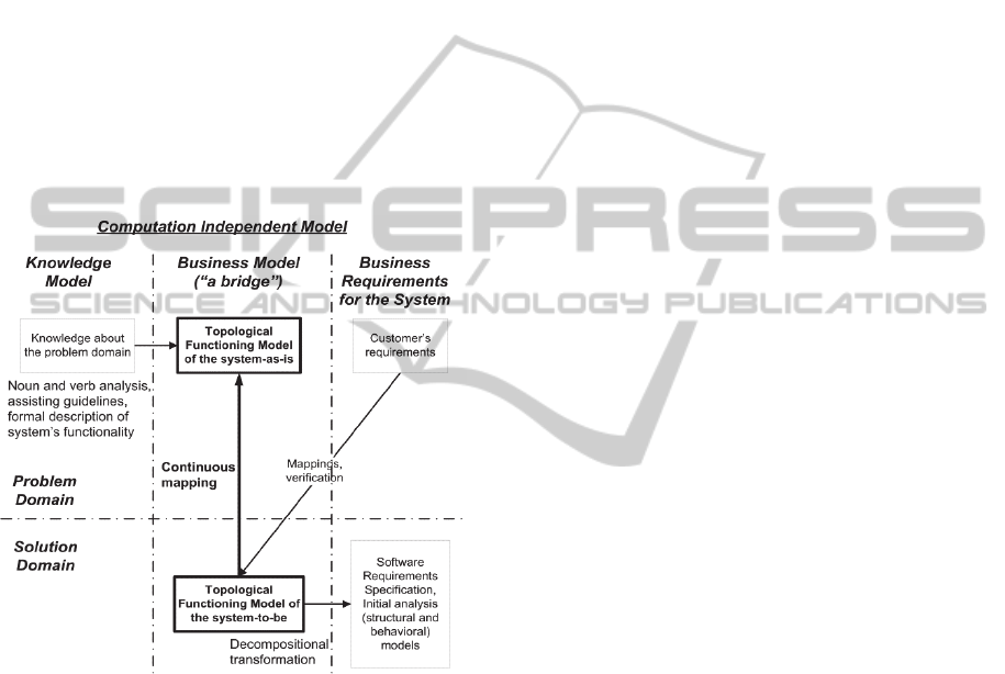
environment (closure, continuous mapping).
Continuous mapping is a mechanism that allows
providing conformity between a solution domain
and a problem domain presented by the topological
functioning models (Figure 2). It serves for
abstracting and refining the TFM, as well as for
analysis of similarities and differences of models.
However, this property does not influence the
subject of the research.
Figure 2: “Bridging” the problem and the solution
domains by using the TFM.
2.2 Topological Relationships
2.2.1 Background
The informal definition of cause-and effect relations
has been discussed in (Asnina, 2012). It is based on
knowledge about causality summarized in (Asnina
and Osis, 2010) and states that cause-and-effect
relations have a time dimension, may have a
situation when “something is allowed to go wrong”,
may be sufficient (complete) or necessary (partial),
may involve multiple factors as in series, as in
parallel, and have a universal nature, i.e. “there is no
such a problem domain without causes and effects”.
The TFM has two aspects related to cause-and-
effect relations. We may distinguish causes and
effects. The causes are input arcs to a vertex and
connect this vertex with functional features (other
vertices) that are necessary or sufficient for its
generation. The effects are output arcs from the
vertex and connect this vertex with other functional
features (vertices) that may be triggered if the
functional feature represented by this vertex occurs
and successfully terminates.
At the beginning of research on TFM
transformations we have used some simplification,
namely we have assumed that all causes are
sufficient and we have had no any explicit means for
determination and specification of multiplicity of
functional factors. This leaded to hardened
automatic branching of logical flows in case of
transformations from the TFM to the behavioural
specifications. For example, transformation from the
TFM to UML activity diagrams required obligatory
human participation in cases of multiple effects and
multiple causes.
At the same time, Uldis Donins in (Donins,
2012-a) suggested his formal definition of a cause-
and-effect relation (using a synonym “topological
relationship”) and logical relationships on a set of
cause-and-effect relations. In his work, a cause-and-
effect relation is defined as a unique 5-tuple <Id, X
c
,
X
e,
L
out
, L
in
> of a binary relationship between cause
functional feature X
c
and effect functional feature X
e
,
as well as two optional sets, namely L
out
– a set of
logical relationships between topological
relationships on outgoing arcs of cause functional
feature X
c
, and L
in
– a set of logical relationships
between topological relationships on incoming arcs
of effect functional feature X
e.
In turn, each logical relation L
id
is defined as a 3-
tuple <Id, T, Rt> that contains a set of topological
relationships T belonging to that logical relationship
type Rt that is one of logical operators AND, OR, or
XOR. Identification of the logical relationship type
is based on combinations of preconditions of effect
functional feature X
e
.
In (Asnina, et al., 2013) we have defined a cause-
and-effect relation as a 5-tuple <C, E, N, S, Refs>,
where:
C (a cause) is a functional feature that
generates E, it cannot be empty;
E (an effect) is a functional feature that is
generated by C, it cannot be empty;
N is the necessity of C for generating E; a
value is true or false;
S is the sufficiency of C for generating E; a
value is true or false;
ENASE2015-10thInternationalConferenceonEvaluationofNovelSoftwareApproachestoSoftwareEngineering
366

Refs (references) is a set of unique tuples
<Ref_Ids, LOp>, where Ref_Ids is a set of
tuples <C*, E*> of cause-and-effect relations,
which participate in logical operator LOp
together; and <C, E> is not equal to <C*, E*>.
The necessity N and sufficiency S come from
classical logic. They induce substantial and
consistent effects on conditional reasoning
performance. The necessity of the cause is
determined when the occurrence of the effect
indicates the occurrence of the cause. The
sufficiency of the cause is determined when the
occurrence of the cause indicates the occurrence of
the effect. The necessary and sufficient cause is
when the occurrence of the effect is possible if and
only if the cause occurred, and occurrence of the
effect indicates the obligatory occurrence of the
cause.
Later, we have excluded Refs element from the
cause-and-effect definition and moved logical
combination to the definition of a functional feature.
Thus, in (Asnina and García-Bustelo, 2014) we
extended the initial definition of a functional feature
in form of 7-tuple <A, R, O, PrCond, PostCond, Pr,
Ex> with two elements <InRel, OutRel>, where:
InRel is an expression of combinations of
possible logical relations among incoming
cause-effect relations in
1
, in
2
, …, in
i
;
OutRel is an expression of combinations of
possible logical relations among outgoing
cause-effect relations out
1
, out
2
, …, out
i
.
A logical relation is presented as an operator
from classical logic such as conjunction (AND) and
disjunction (OR, XOR). Conjunction indicates a
synchronous occurrence of referenced causes.
Disjunction indicates an asynchronous occurrence of
referenced causes.
In (Asnina, et al., 2013) identification of the
logical relationship type is based on analysis of
necessity and sufficiency of causes.
2.2.2 Refined Definitions
Here we present the refined definition of a
topological cause-and-effect relation in the TFM
based on the previous research results. We skip the
point of identification of logical relationship types
since it is out of scope of this paper.
Formal Definition of a Cause-and-Effect
Relation. A cause-and-effect relation T
i
is a binary
relationship that relates exactly two functional
features X
c
and X
e
. Both X
c
and X
e
may be the same
functional feature in case of recursion. The synonym
for cause-and-effect relation is a topological
relationship. Each cause-and-effect relation is a
unique 5-tuple (1):
T
i
= <ID, X
c
, X
e,
N, S>, where (1)
ID is a unique identifier of a relation;
X
c
is a cause functional feature;
X
e
is an effect functional feature;
N is a Boolean value of the necessity of X
c
for
generating X
e
;
S is a Boolean value of the sufficiency of X
c
for generating X
e
.
Formal Definition of a Logical Relation. A
logical relation L
i
specifies the logical operator
conjunction (AND), disjunction (OR), or exclusive
disjunction (XOR) between two or more cause-and-
effect relations T
i.
The logical relation denotes
system execution behaviour (e.g., decision making,
parallel or sequential actions). Each logical relation
is a unique 3-tuple (2):
L
i
= <ID, T, R
T
>, where (2)
ID is a unique identifier of a relation;
T is a set of cause-and-effect relations {T
i
, ...,
T
n
}
that participate in this logical relation;
R
T
is a logical operator AND, OR, or XOR
over T; operator OR is a default value.
Formal Definition of Incoming Topological
Relations. A set of logical relations that joins cause-
and-effect relations, which income into functional
feature X
i
, is defined as a subset L
in
of set L = {L
i
,
..., L
n
}, where at least one topological relation T
i
such that its effect functional feature X
e
is equal to
X
i
is found in set T of topological relations in each
logical relation L
i
.
Formal Definition of Outgoing Topological
Relations. A set of logical relations that joins cause-
and-effect relations, which outgo from functional
feature X
i
, is defined as a subset L
out
of set L = {L
i
,
..., L
n
}, where at least one topological relation T
i
such that its cause functional feature X
c
is equal to
X
i
is found in set T of topological relations in each
logical relation L
i
.
2.2.3 Visual Specification
As illustrated in Figure 1 and Figure 3, the TFM can
be visualized as a directed graph, where cause-and-
effect relations are visually represented as directed
arcs among vertices. As previously mentioned,
logical relations among cause-and-effect relations
may by quite complex (see Figure 3).
There is no native mechanism for visual
specification of logical relations among cause-and-
effect relations in the TFM. Uldis Donins in
SpecificationofDecision-makingandControlFlowBranchinginTopologicalFunctioningModelsofSystems
367

Figure 3: TFM representing enterprise data
synchronization system functioning (borrowed from
(Donins, 2012)).
(Donins, 2012-a) suggested using visual constraints
hanged on arcs as illustrated in Figure 3. Each
logical relation is represented as a connector, i.e. a
line that connects all needed cause-and-effect
relations, with a label that indicates the logical
operator.
Such a visualization is not complete since: 1) it
does not illustrate necessity and sufficiency of
cause-and-effect relations, and 2) it adds additional
elements to the digraph that may harden its
readability and comprehensibility in case of complex
relations as Figure 3 illustrates. Besides that, the
TFM lacks a mechanism for specifying this
information in a flexible and easy modifiable, but
formalized manner.
Therefore, in the next section we will assess
possible specification mechanisms that are used or
suggested in wide-used behavioural diagrams and
process models and their suitability for the TFM.
3 VISUAL MEANS FOR
SPECIFICATION OF FLOW
BRANCHING AND DECISIONS
In all of the further considered models and notations,
control (or message) flows use several elements that
highlight different aspects of flow activation or
message sending. The common is that
activation/sending conditions are visualized as labels
and additional symbols on the flows.
Other aspects of instances of processes, activities
and tasks such as loops, parallel and sequential
execution also may be specified as additional
symbols on nodes, e.g., like in BPMN.
3.1 Forks, Joins, Getaways, Logical
Connectors, Decisions
Flowcharts provide the simplest visual means for
representation of flow branching and decisions.
There are multiple information sources that explain
meaning of flowchart symbols. According to (Hebb,
2015), flowcharts use the following symbols for
branching of flows:
Decision – a labelled or non-labelled diamond
that indicates a question or branch in the
process flow, if there are two possible options
such as yes/no or true/false. Options are
presented as a text on flow arrows. Question
answering which one or another option is
evaluated is located within the diamond.
However, in other implementations the
decision node allows multiple outgoing
options (ARIS Community, 2019-2015). It
performs a logical XOR on its output flows;
Merge (inverted triangle), Summing Junction
(circle with X inside) – two elements with the
same meaning: both indicate the merging of
multiple processes into a single one; however,
they are seldom used in process modelling
(logical OR);
Extract – a triangle that shows when a process
splits into parallel paths (logical AND);
Or - a circle with the plus symbol inside that
shows when a process diverges (usually for
more than two branches). It is required to label
the outgoing flows to indicate the conditions
to follow each branch. It performs a logical
OR on its outgoing flows.
The UML activity diagram is a kind of
behavioural diagrams proposed in the UML. This
type of diagrams is widely supported by modelling
tools. Starting from UML 2.0, activity diagrams use
formalism of Petri Nets (Section 3.2) for modelling
data and control flows. According to UML 2.0
(Arlow and Neustadt , 2005), the following elements
are used for branching flows in activity diagrams:
Decision node – it is the output edge whose
guard condition if true is traversed. May
optionally have a “decisionInput”, i.e. a guard
condition for the decision node itself. This
node has one input edge and two or more
output edges, each of which is protected by a
guard condition. All guard conditions must be
mutually exclusive (XOR), otherwise the
behaviour of the node is formally undefined.
Guards are visualized as labels on
corresponding edges;
ENASE2015-10thInternationalConferenceonEvaluationofNovelSoftwareApproachestoSoftwareEngineering
368

Merge node – copies input tokens to its single
output edge. It has two or more input edges
and a single output edge. All triggered
incoming flows are merged and trigger one
outgoing flow. It is not mandatory to have all
possible incoming flows triggered (OR);
Fork node – splits the single incoming flow
into multiple concurrent outgoing flows
(AND);
Join node – synchronizes all multiple
concurrent flows into the single outgoing edge
(AND). May optionally have a join
specification to modify its semantics.
Business Process Model and Notation (BPMN)
is a standard for business process modelling
developed by the Object Management Group
(OMG). It has many different notational constructs
for representation of various modelling aspects
related to control, data an event flows.
According to (Object Management Group,
2011), BPMN suggests the following visual
elements for control on flows:
Getaways – BPMN suggests several getaway
types visualized as diamonds with additional
symbols. Exclusive getaway may split the
incoming sequence flows. It routes the
sequence flow to exactly one of the outgoing
branches based on conditions (XOR).
Conditions are visualized as labels on flows.
In case of merging, it awaits one incoming
branch to complete before triggering the
outgoing flow (XOR). Another type is an
inclusive getaway. It may split the incoming
flows, and then one or more branches are
activated based on branching conditions (OR).
When merging, it awaits all active incoming
branches to complete (OR). Parallel getaway
splits the sequence flow so that all outgoing
branches are activated simultaneously (AND).
When merging parallel branches it waits for
all incoming branches to complete before
triggering the outgoing flow (AND). Complex
getaways are used for complex combinations
of synchronous and asynchronous branches.
Event-based getaways – they are always
followed by catching events or receiving
tasks. The sequence flow is routed to the
subsequent event/task which happens first.
Triggered processes may be executed in
parallel or in series.
The Event-driven Process Chain (EPC) is a
flowchart based diagram that combines events and
processes such that processes are triggered by events
(Davis and Brabander, 2007). According to
(Gottschalk, et al., 2008) EPCs have three node
types, namely functions, event, and logical
connectors. Functions are active elements, while
events are passive. Events indicate prerequisites for
or results from the execution of functions.
The logical connectors determine the control
flow behaviour. There are three possible logical
connectors, namely XOR (exclusive OR), OR and
AND. Visually they are represented as circles with
mathematical symbols inside them. The meaning of
them is the following:
XOR – means that if it splits the control flow
into two and more successors, then at runtime
only one output flow of them is followed.
When joins, it requires the input just from the
only one incoming arc to forward a case;
OR means that if it splits the control flow into
two and more successors, then at runtime one
or more (not obligatory all of) output flows
are followed. When joins, it requires a number
of incoming arcs, but not all of the defined;
AND - means that if it splits the control flow
into two and more successors, then at runtime
all output flows are followed. When joins, it
requires input from all incoming arcs to
forward the case.
3.2 Places and Transitions
Petri Nets (PNs) is a formal mathematical and
graphical language for modelling systems with
concurrency and resource sharing, which can be
applied for any area or system that can be described
graphically like flowcharts. PNs can be used to
represent flows of both control and data. Powerful
PNs extensions are Coloured Petri Nets (CPNs)
(Kristensen M., et al., 1998), (Jensen, 1994), (Lakos,
2011) and workflow (WF) nets (van der Aalst,
1998).
A Petri net is a particular kind of a digraph
(directed, weighted, bipartite), which contains two
kinds of nodes – places and transitions, which are
connected by directed arcs. Arcs are directed from a
place to a transition or from a transition to a place.
Arcs are labelled with their weights (classically they
are positive integers). In the PNs, places represent
conditions, and transitions represent events. An
event has a certain number of conditions that must
be true in order to generate the event. The same, a
transition has a certain number of input and output
places correspondingly to the pre-conditions and
post-conditions of the event. The status of the
conditions, true or false, is indicated by the presence
or absence of a token in the place, correspondingly.
SpecificationofDecision-makingandControlFlowBranchinginTopologicalFunctioningModelsofSystems
369

Interpretation of places and transitions may differ
(Murata, 1989), e.g., i) pre-condition, event, post-
condition, ii) input data, computation step, output
data, iii) resources needed, task or job, resources
released, etc.
Control flows can be modelled in different ways.
The common construct used for this purpose is a
scheme, when place p
i
has two outgoing arcs: one to
transition t
m
and one to transition t
n
. This construct is
called a conflict, choice, or decision. There are some
basic examples that are useful in modelling (Murata,
1989):
Decisions are represented by using state machines
(the previously mentioned construct of p
i
, t
m
and
t
n
), but state machines do not represent the
synchronization of parallel activities;
Parallel activities (i.e., logical operator AND on
the outgoing control flows from the event) are
represented by concurrent transitions (which are
causally independent, i.e., one transition may fire
before or after or in parallel with the other).
Besides that each place in the net must have
exactly one incoming and one outgoing arc
(Figure 4-a);
Conflicts (i.e., logical operators OR and XOR on
the outgoing control flows) are a more complex
case. Two events e1 and e2 are in conflict if either
e1 or e2 can occur but not both (XOR), and they are
concurrent if both events can occur in any order
without conflicts (OR). The situation when conflicts
and concurrency are mixed is called confusion
(Figure 4-b).
Logical conditions on firing the transition are
modelled as logical expressions or valid token
colours.
Figure 4: Petri nets for representation of parallel activities
(a) and symmetric confusion (b).
3.3 Decision Models
Decision Model and Notation (DMN) is one of
standards proposed by the OMG for business
process modelling. Its version 1.0 – Beta 1 was
presented on February 2014 (Object Management
Group, 2014), according to which “a decision is
defined as the act of determining an output value
(the chosen option), from a number of input values,
using logic defining how the output is determined
from the inputs”.
A decision model in DMN consists of a Decision
Requirements Graph (DRG) depicted in one or more
Decision Requirements Diagrams (DRDs). DRDs
use such elements as a decision (explained above), a
business knowledge model, an input data element,
and a knowledge source element.
Business knowledge models in the form of
business rules, analytic models, decision tables, or
other formalisms describe a decision logic. It allows
specifying a complete set of business rules and
calculations, and (if desired) allows the decision-
making to be fully automated. This means that
decision logic may be specified with prescriptive or
descriptive rules. Input data elements serve as
parameters to the knowledge models, while
knowledge sources denote authorities for a business
knowledge model or decision.
Decision-making modelled in DMN may be
mapped to tasks or activities within a business
process, e.g. using BPMN as suggested in the DMN
1.0 specification.
Let’s consider one of the ways how the decision
logic may be expressed, i.e. a decision table. A
decision table consists of a name, a set of inputs, a
set of outputs, and a list of rules in rows or columns
of the table. Each rule is composed of the specific
input entries and output entries of the table row or
column. Each input (or output) optionally is
associated with a type and list of input (or output)
values. The list of rules expresses the logic of the
decision. If rules are allowed to contain overlapping
input combinations, the table hit policy indicates
how overlapping rules must be interpreted. The list
of rules may contain all possible combinations of
input values, thus forming a “complete” table.
Hence, a decision table is a way how to model
and visualize complex decisions, i.e. combinations
of logical operators XOR, OR and AND on input
data, while keeping the decision logic separately
from process models. Other ways may be used for
less complex decision logics, while keeping the
business rules and decision logic separately from the
process models, thus providing modifiability of the
decision logic.
The decision table requires that all input data
were complete and exclusive, i.e. all possible
combinations of non-overlapping inputs must be
presented there. However, combinations of input
data may overlap, but the hit policy must clearly
ENASE2015-10thInternationalConferenceonEvaluationofNovelSoftwareApproachestoSoftwareEngineering
370

Table 1: Comparison of the specification means.
Characte-
ristics
LO FC UAD BPMN EPC WF net DMN
Specification of completeness of incoming and outgoing flows
Necessity - - - - - Tokens and
firing
conditions
Complete
-ness and
overlaps
check
Sufficiency - - - - -
Specification of logical relations among outgoing flows (splitting)
XOR Connector,
conditions
Decision
node with
exclusive
outputs
Decision
node with
exclusive
outputs
Exclusive/
event-based
getaway
Correspon-
ding
connector,
events
Places,
transitions,
tokens
Logical
expres-
sions,
decision
tables
OR Connector,
conditions
OR node/
branches
with
conditions
- Inclusive/
event-based
getaway
AND Connector Extract
node
Fork node Parallel/event-
based getaway
Complex
combina-
tion
Elements
combination
Elements
combinatio
n
Elements
combinatio
n
Getaway
combination/
complex one
Elements
combination
Places,
transitions,
tokens
Decision
Tables
Specification of logical relations among incoming flows (merging)
XOR Correspon-
ding
connector
- - Exclusive/
event-based
getaway
Correspon-
ding
connector,
events
Places,
transitions,
tokens
Logical
expressio
n and
decision
tables
OR Merge,
Summing
Junction
nodes
Merge node Inclusive/
event-based
getaway
AND - Join node Parallel/event-
based getaway
Complex
combina-
tion
A set of
connectors
Elements
combinatio
n
Elements
combinatio
n
Getaway
combination/
complex one
Elements
combination
Places,
transitions,
tokens
Decision
Tables
Visualisation elements
Splitting Labels Nodes,
labels
Nodes,
labels
Nodes, labels Nodes Nodes,
labels
Labels,
tables
Merging Labels Nodes Nodes Nodes Nodes Nodes,
labels
Labels,
tables
Separate
location
No No No No No No Yes
TFM characteristics in case of integrated using
Compactne
ss (simple)
The same Lower Lower Lower Low (added
events)
Low The same
Compact-
ness
(complex)
Low Low Low Low Low Low The same
Apprehensi
bility
Low if
complex
combina-
tions
May be
ambiguous
May be
lower if
complex
behaviour
Lower due to
notation
diversity
The same or
higher
Lower The same
or higher
Modifiabili
ty
The same Lower Lower Lower Lower Lower The same
or higher
Accuracy Higher Lower Higher Higher Higher Higher Higher
Abstraction The same Lower Lower Lower Lower Lower The same
SpecificationofDecision-makingandControlFlowBranchinginTopologicalFunctioningModelsofSystems
371

state how these overlapping rules have to be
interpreted. There could be the single and the
multiple outputs according to the indicated hit
policy.
3.4 Comparison and Evaluation
So far, we have discussed in brief several
approaches, namely logical operators as connectors
(LO), flowcharts (FC), UML activity diagrams
(UAD), BPMN, EPC, WF nets, and DMN. They
provide different elements for specification and
visualization of logical conditions on control flows.
We have defined characteristics of the
specification means that we want to use together
with the TFM. The characteristics and comparison
are illustrated in Table 1.We have compared the
considered approaches from five aspects:
specification of completeness of incoming and
outgoing flows, specification of splitting and
merging, visualisation elements, and possible
influence of these elements on the TFM
characteristics in case of integrated using.
Specification of completeness of incoming and
outgoing flows is not supported in all approaches but
DMN. The DMN states that all input data must be
complete (i.e. all possible combinations must be
presented) in order to get a set of outputs, besides
that all overlaps or incompleteness in input or output
data must be solved by using the explicitly specified
hit policy for each decision table.
All the approaches use special additional labelled
or non-labelled nodes or combinations (patterns) of
basic elements for specifying logical relations
among sets of incoming or outgoing flows. Outgoing
flows are labelled with conditions that if true are
traversed. Only DMN decision models are placed
separately and have links with the processes and
tasks. Other approaches embed decision elements
into the main model.
Next, we could evaluate how these approaches
would affect such TFM characteristics as
compactness, apprehensibility, modifiability and
accuracy of specification of logical relations, as well
as the level of abstraction in the model.
Compactness means keeping the same size of the
TFM digraph, i.e. we prefer not to add additional
nodes or patterns of elements. A simple case of
logical relations is when a single logical operator is
on the set of cause-and-effect relations. A complex
case is when two or more logical operators are on
the same set of cause-and-effect relations.
Apprehensibility is lower when such additional
constructs are added, since it requires additional
efforts to understand the model. Modifiability is the
higher, the less elements in the digraph are affected
by changes. Accuracy of specification is the higher,
the less ambiguity is allowed. And the last, the level
of abstraction in the model is the same, if additional
elements do not adds more specialized data to the
digraph, e.g., data about events occurred or
questions asked.
From these aspects, logical operators hanged on
arcs and decision models are the most suitable, i.e.
the former are appropriate in case simple logical
relations, whereas the latter are more appropriate in
case of complex logical relations.
4 CONCLUSIONS
In order to find the most suitable mechanisms we
have considered native mechanisms in BPMN, UML
Activity Diagrams, EPCs, flowcharts, workflow
Petri Nets, and Decision Models. Evaluation of these
models and provided specification mechanisms
showed that a use of logical operators as we do it at
the present and decision models of the DMN is more
appropriate for our goal. The weakness of logical
operators visualized as labels on connectors of flows
is that they decrease compactness and
comprehensibility of the model in case of complex
logical combinations. However, the decision models
are more powerful in such cases. Besides that, the
decision models are separate from the main model
and could be modified independently. The decision
models may be assigned to the TFM using extension
of the DMN metamodel.
The obtained results need to be validated for
cases where systems have the complex behaviour
and various logical relations among control flows.
The future r esearch direction is related to validation
of the obtained results and integration of the
corresponding approaches with the TFM.
REFERENCES
ARIS Community, 2019-2015. Flowchart: Overview of
the Flowchart notation. (Online) Available at:
http://www.ariscommunity.com/flowchart (Accessed
2015).
Arlow, J. & Neustadt, I., 2005. UML 2 and the Unified
Process: Practical Object-Oriented Analysis and
Design. 2nd ed. s.l.:Addison-Wesley Professional.
Asnina, E., 2012. Notion of Causal Relations of the
Topological Functioning Model. Applied computer
systems, Volume 13, pp. 68-73.
Asnina, E. & García-Bustelo, B., 2014. The Perspective on
ENASE2015-10thInternationalConferenceonEvaluationofNovelSoftwareApproachestoSoftwareEngineering
372

Data and Control Flow Analysis in Topological
Functioning Models by Petri Nets. Applied Computer
Systems, Volume 16, pp. 77-84.
Asnina, E. & Osis, J., 2010. Computation independent
models: bridging problem and solution domains. In:
Proceedings of the 2nd International Workshop on
Model-Driven Architecture and Modeling Theory-
Driven Development MDA & MTDD 2010, In
conjunction with ENASE 2010, Athens, Greece, July
2010. Lisbon: SciTePress, pp. 23--32.
Asnina, E., Osis, J. & Jansone, A., 2013. Formal
Specifications of Topological Relations. In: Databases
and Information Systems VII: Selected Papers from
the Tenth International Baltic Conference (DB&IS
2012), Lithuania, Vilnius, 8-11 July, 2012.
Amsterdam: IOS Press, pp. 175-188.
Davis, R. & Brabander, E., 2007. The Event-driven
Process Chain. In: ARIS Design Platform. London:
Springer, pp. 105-125.
Donins, U., 2012-a. Semantics of Logical Relations in
Topological Functioning Model. In: Proceedings of
the 7th International Conference on Evaluation of
Novel Approaches to Software Engineering (ENASE
2012), Poland, Wrocław, 29-30 June, 2012. Lisbon:
SciTePress, pp. 217-223.
Donins, U., 2012. Topological Unified Modeling
Language: Development and Application. PhD Thesis.
Rīga: RTU.
Donins, U. et al., 2011. Towards the Refinement of
Topological Class Diagram as a Platform Independent
Model. In: Proceedings of the 3rd International
Workshop on Model-Driven Architecture and
Modeling-Driven Software Development (MDA &
MDSD 2011). Lisbon: SciTePress, pp. 79-88.
Gottschalk, F., van der Aalst, W. M. P. & Jansen-Vullers,
M. H., 2008. Merging Event-Driven Process Chains.
In: On the Move to Meaningful Internet Systems: OTM
2008. LNCS. Berlin: Springer Berlin Heidelberg, pp.
418-426.
Hebb, N., 2015. Flowchart Symbols Defined: Business
Process Map and Flow Chart Symbols and their
Meanings. (Online) Available at:
http://www.breezetree.com/article-excel-flowchart-
shapes.htm.
Jensen, K., 1994. An Introduction to the Theoretical
Aspects of Coloured Petri Nets. In: A Decade of
Concurrency, LNCS. Berlin: Springer-Verlag, pp. 230-
272.
Kristensen M., L., Christensen, S. & Jensen, K., 1998. The
practitioners’ guide to coloured Petri nets. Int Journal
on Software Tools for Technology Transfer, Issue 2,
pp. 98-132.
Lakos, C., 2011. Object Oriented Modelling with Object
Petri Nets. In: Concurrent Object-Oriented
Programming and Petri Nets, LNCS, Vol. 2001.
Berlin: Springer, pp. 1-37.
Mukerji, J. & Miller, J., 2003. MDA Guide v1.0.1.
(Online) Available at: http://www.omg.org/cgi-
bin/doc?omg/03-06-01.
Murata, T., 1989. Petri Nets: Properties, Analysis and
Applications. Proceedings of the IEEE, 77(4), pp. 541-
580.
Object Management Group, 2011. Business Process
Model and Notation (BPMN): Version 2.0. [Online]
Available at: http://www.omg.org/spec/BPMN/2.0/
(Accessed 2015).
Object Management Group, 2014. Decision Model and
Notation (DMN). (Online) Available at:
http://www.omg.org/spec/DMN/ [Accessed 2015].
Osis, J., 1969. Topological Model of System Functioning.
Automatics and Computer Science, J. of Acad. of Sc.,
Issue 6, pp. 44-50.
Osis, J., 1972. Diagnostics of complex systems
(Dissertation of Dr. Habil. Sc. Eng.). Riga, Latvia:
Latvian Academy of Sciences.
Osis, J. & Asnina, E., 2011-a. Topological Modeling for
Model-Driven Domain Analysis and Software
Development. In: Model-Driven Domain Analysis and
Software Development: Architectures and Functions.
Hershey, New York, USA: IGI Global, pp. 15-39.
Osis, J. & Asnina, E., 2011-d. Derivation of Use Cases
from the Topological Computation Independent
Business Model. In: Model-Driven Domain Analysis
and Software Development: Architectures and
Functions. Hershey, USA: IGI Global, pp. 65-89.
Osis, J. & Asnina, E., 2011. Model-Driven Domain
Analysis and Software Development: Architectures
and Functions. Hershey, New York, USA: IGI Global.
Osis, J., Asnina, E. & Garcia-Diaz, V., 2014.
Dependencies among Architectural Views Got from
Software Requirements Based on a Formal Model.
Applied Computer Systems, Volume 16, pp. 5-12.
Osis, J., Asnina, E. & Grave, A., 2008. Formal Problem
Domain Modeling within MDA. In: Communications
in Computer and Information Science (CCIS).
Software and Data Technologies. Berlin: Springer-
Verlag, pp. 387-398.
Selic, B., 2003. The pragmatics of model-driven
development. IEEE Software, pp. 19-25.
Slihte, A. & Osis, J., 2014. The Integrated Domain
Modeling: A Case Study. In: Databases and
Information Systems: Proceedings of the 11th
International Baltic Conference (DB&IS 2014),
Estonia, Tallinn, 8-11 June, 2014.. Tallinn: Tallinn
University of Technology Press, pp. 465-470.
Slihte, A., Osis, J. & Donins, U., 2011. Knowledge
Integration for Domain Modeling. In: Model-Driven
Architecture and Modeling-Driven Software
Development: ENASE 2011, 3rd Whs. MDA&MDSD.
Lisbon: SciTePress, pp. 46-56.
van der Aalst, W., 1998. The Application of Petri Nets to
Workflow Management. The Journal of Circuits,
Systems and Computers, 8(1), pp. 21-66.
SpecificationofDecision-makingandControlFlowBranchinginTopologicalFunctioningModelsofSystems
373
