
Determination and Control of the Satellites’ Attitude by using a
Pyramidal Configuration of Four Control Moment Gyros
Romulus Lungu
1
, Mihai Lungu
2
and Mihai Ioan
3
1,2
University of Craiova, Faculty of Electrical Engineering, Carol Blv., no. 6, Craiova, Romania
3
University “Politehnica” of Bucharest, Faculty of Aerospace Engineering, Bucharest, Romania
Keywords: Control Moment Gyro, Pyramidal Configuration, Satellite, Attitude Control.
Abstract: The paper presents a new architecture for mini-satellites’ attitude control using a cluster consisting of four
control moment gyros, in pyramidal configuration, and feedback from the quaternion and angular velocity
vectors. The designed control law modifies the cluster’s equivalent gyroscopic moment, the equivalent kinetic
moment and the angular velocities’ vector, this leading to the modification of the quaternion vector and to the
change of the satellite‘s attitude. Matlab environment is used for the architecture’s software implementation
and validation, this being achieved for a mini-satellite involved in a typical motion around its own axis.
1 INTRODUCTION
To have multiple capabilities (missiles’ tracking, land
mobile targets’ tracking etc.), the satellites must have
good rotational handling and agility. Such satellites
need an automatic system for their attitude’s control
(ASAC) by performing fast slewing maneu-vers; the
fast repositioning maneuvers are influenced by the
physical limitations of the sensors and actu-ators, by
the structural rigidity of the satellites and by
the
mission’s type (Jovanovic, 2014; Bouwmeester and
Guo, 2010; Lavet, 2010).
The performances of the ASACs are limited by the
satellites’ dimensions, especially in the case of small
satellites’ usage. In these cases, the gyroscopic wheels
can not assure good agility because their limited
capability to create control couples (maximum 1.5
Nm) (Wie et al., 2002; Berner, 2005; Lungu, 2008);
therefore, in these cases, the control moment gyros
(CMGs)
are ideal because these can generate significant
control couples (100-3000 Nm). As actuators, the
CMGs have been used on large cosmic devices
(Skylab, MIR, ISS) and, recently, on mini-satellites.
The most important drawback of CMGs is related to
the singularities’ appearance (Ford and Hall, 2000);
for particular values of the gyroscopic frames’ angles,
the CMGs do not produce big enough couples and the
gyroscopic frames get stuck; therefore, special control
laws must be designed to avoid such situations.
The CMGs may be single-gimbals type (SGCMG)
of double-gimbals type (DGCMG); for the DGCMGs,
the control law can easily avoid the singularities, due
to their extra degree of freedom, but the SGCMGs are
simpler in terms of construction and hardware, having
many other advantages related to their price, power
and reliability (Berner, 2005).
By CMGs grouping, the clusters are obtained; the
most used clusters are the pyramidal ones, having four
CMGs; such configuration is presented in our paper.
In this paper, the authors propose a new archi-
tecture for the control of the mini-satellites’ attitude; it
is based on a cluster consisting of four control moment
gyros and uses feedback from the system’s quaternion
vector (which gives information regarding the attitude
of the satellite) and satellite’s angular rates. The
control law to be designed will modify the equivalent
gyroscopic moment of the cluster, the equivalent
kinetic moment, and the angular rates’ vector, this
leading to the modification of the quaternion and to the
change of the satellite‘s attitude. The new architecture
is implemented and validated through complex
numerical simulations for the case of a mini-satellite
involved in a typical maneuver around
its own axis.
2 PYRAMIDAL CONFIGURATION
WITH FOUR CMGS
We consider the motion of a mini-satellite which
performs a typical maneuver (a complete cycle)
around
its own axis (with constrained angular speed);
448
Lungu R., Lungu M. and Ioan M..
Determination and Control of the Satellites’ Attitude by using a Pyramidal Configuration of Four Control Moment Gyros.
DOI: 10.5220/0005507304480456
In Proceedings of the 12th International Conference on Informatics in Control, Automation and Robotics (ICINCO-2015), pages 448-456
ISBN: 978-989-758-122-9
Copyright
c
2015 SCITEPRESS (Science and Technology Publications, Lda.)
the three phases of motion (the accelerated angular
motion, the uniform angular motion and the braked
motion) are described in detail in (Wie and Lu, 1995).
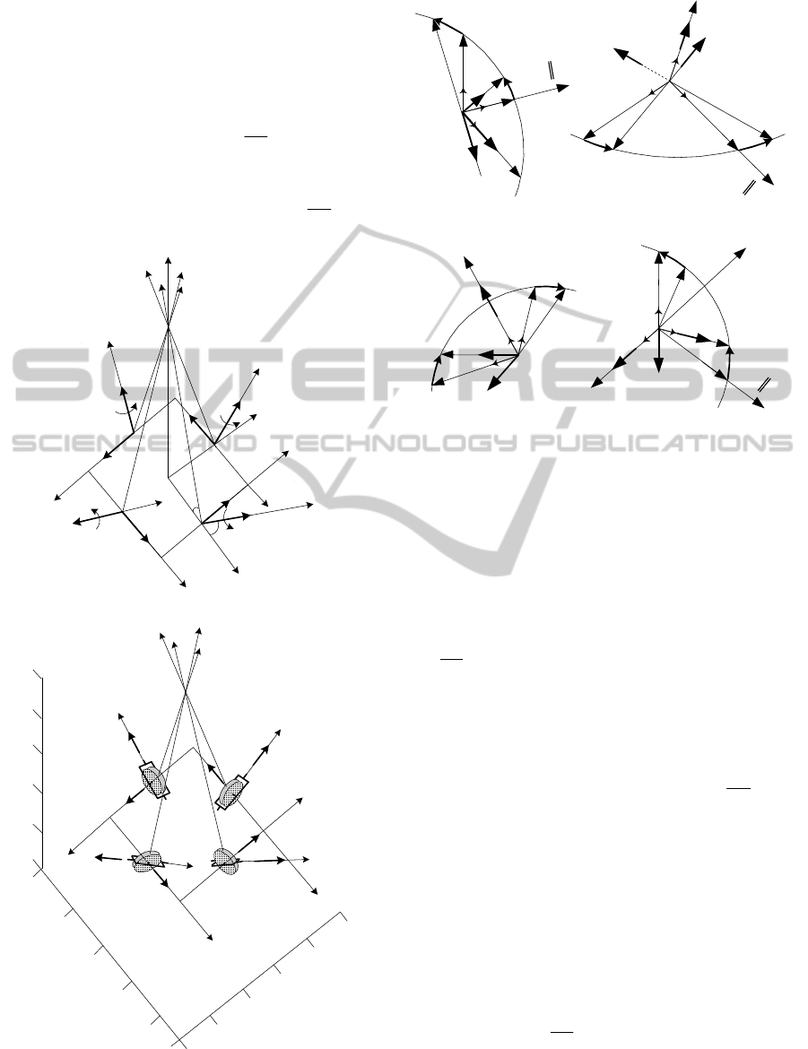
To control the satellite, a gyro system (a cluster
having pyramidal configuration), consisting of four
control moment gyros, is used. The pyramidal confi-
guration is presented in Fig. 1.
The gyros’ rotation
axes (the kinetic moments
4,1, iK
i
) are initially
oriented parallel to the sides of the pyramid base, the
axes of the
gyroscopic frames (the angular velocities
associated to the frames’ rotations
,
i
4,1i
) are
Z
1
z
2
z
3
z
4
z
3
x
3
3
C
M
G
3
o
3
K
3
y
4
x
4
y
O
4
4CMG
4
o
4
K
2
2CMG
2
o
2
K
Y
1
o
X
1
2
y
2
x
1
y
1CMG
90
1
x
1
K
a.
Z
1
z
2
z
3
z
4
z
3
x
3
3CMG
3
K
3
y
4
x
4
y
4
K
2
2CMG
2
K
1
2
y
2
x
1
y
1CMG
1
x
1
K
4
X
Y
4CMG
b.
Figure 1: Pyramidal configuration with four CMGs.
1
z
1
y
1
1
1
y
1
o
1
1
z
1
K
1
k
O
Y
11
, xx
1
i
1
j
1
g
M
a. b.
2
x
2
z
2
2
z
2
x
2
o
2
O
X
2
i
2
k
2
j
2g
M
2
2
,
y
y
2
2
K
d.
4
z
4
x
4
4
4
x
4
o
4
z
4
K
O
X
4
4
y
4
4
,
yy
4g
M
c.
3
y
3
y
3
3
3
z
3
z
3
o
3
K
3
i
3
3
3
,
x
x
3
g
M
4
i
4
k
4
j
3
j
3
k
Figure 2: The rotations of the gyroscopic frames, angular
variables, kinetic moments and gyroscopic couples.
perpendicular to the side faces of the pyramid, while
the transversal axes of the CMGs are perpendicular to
the gyro axes and gyroscopic frames. In Fig. 2, one
presents the rotations of the gyroscopic frames, the
angular variables, the kinetic moments and the gyros-
copic couples. The frame S (satellite
linked) is denoted
with OXYZ. The gyroscopic tied frames are ,
iiii
zyxo
;4,1i
initially (in the absence of the gyroscopic
frames’ rotations, we have
0
i
); these frames are
oriented towards the axes of the frames
iiii
zyxo .
For the beginning, let us consider that the pyramid
base
is fixed
0
and, by rotation of the gyroscopic
frames with the angular velocities
,4,1, i
i
the
gyros react by gyroscopic couples (Wie et al., 2002):
.d/d, tKKKKM
iiiiigi
(1)
In figs. 1 and 2, there are highlighted the rotations
of the gyroscopic trihedrals with respect to the
initial
positions
,
iiii
zyxo
the angular variables (
i
and
i
),
the directions of the kinetic moments
i
K
after the
rotations of the gyroscopic frames characterized by the
rotation
angles
i
and the gyroscopic couples –
;
gi
M
,4,1,,, ikji
iii
represents the axes’ versors
of the trihedrals
.
iiii
zyxo
By means of Fig. 1 and
equation (1), one can obtain the four gyroscopic
DeterminationandControloftheSatellites'AttitudebyusingaPyramidalConfigurationofFourControlMomentGyros
449

moments:
;
cossin
00
sincos0
111
111
11111111
1
1111
111
11
zzy
ggg
g
MMM
kKjK
KK
kji
KM
(2)
;
cossin
00
sin0cos
222
222
22222222
2
2222
222
22
zzx
ggg
g
MMM
kKiK
KK
kji
KM
(3)
;
cossin
00
sincos0
333
333
33333333
3
3333
333
33
zzy
ggg
g
MMM
kKjK
KK
kji
KM
(4)
.
cossin
00
sin0cos
444
444
44444444
4
4444
444
44
zzy
ggg
g
MMM
kKiK
KK
kji
KM
(5)
The component
1
1
y
g
M
acts upon the gyroscopic
frame without rotate it and, thus, it acts on the base (S),
while the component
1
1
z
g
M
acts upon the gyro-frame
ensemble and, thus, on the base. The component
2
2
x
g
M
acts on the gyroscopic frame, while
2
2
z
g
M
acts
on the gyro-frame ensemble and, thus, both com-
ponents act on the base (S). Same conclusion can be
drawn regarding the components
3
3
y
g
M
and
3
3
z
g
M
third
gyro and for the components
4
4
y
g
M
and
4
4
z
g
M
fourth gyro.
According to Fig. 1a, the projections of the
gyroscopic couple
1g
M
(first CMG) on the axes of
the frame S (OXYZ – satellite linked) are:
.sincossin
,sin
,coscoscos
11111
11111
11111
1
1
1
KMM
KMM
KMM
zZ
yY
zX
gg
gg
gg
(6)
Similarly, the projections of the gyroscopic couples
32
,
gg
MM
and
4g
M
on the same axes are deduced
as:
;sincossin
,coscoscos
,sin
22222
22222
22222
2
2
2
KMM
KMM
KMM
zZ
zY
xX
gg
gg
gg
(7)
;sincossin
,sin
,coscoscos
33333
33333
33333
3
3
3
KMM
KMM
KMM
zZ
yY
zX
gg
gg
gg
(8)
.sincossin
,coscoscos
,sin
44444
44444
44444
4
4
4
KMM
KMM
KMM
zZ
zY
xX
gg
gg
gg
(9)
We denote with K and M
g
– the equivalent
kinetic and gyroscopic moments, respectively; these
can be expressed as vectors having the components
upon the three axes and verifying the equations:
;,
T
ggg
T
ZYX
ZYX
MMMKKK
g
MK
(10)
putting together the equations (1)-(5), we get:
g
MK
(11)
or
,
T
ggg
T
ZYX
ZYX
MMMKKK
where
.
,
,
4321
4321
4321
ZZZZZ
YYYYY
XXXXX
ggggg
ggggg
ggggg
MMMMM
MMMMM
MMMMM
(12)
Replacing (6)-(9) in (12), the equation (11) becomes:
,
Q
K
(13)
with (Haruhisa, 1997)
T
4321
and
,
cγsβcγsβcγsβcγsβ
cγcβsγcγcβsγ
sγcγcβsγcγcβ
4321
4321
4321
g
JQ
(14)
where
g
J
(J
g
– the inertia moment and
the
vector of the gyros’ angular velocities) is the module of
ICINCO2015-12thInternationalConferenceonInformaticsinControl,AutomationandRobotics
450

the gyros’ kinetic moments (of the gyroscopic wheels),
.γsinγs,γcosγc,βsinβs,βcosβc
iiii
Furthermore, taking into account the base’s
rotation with the angular velocity
,
the equation of
the pyramidal cluster (containing 4 CMGs – Fig. 1)
becomes (Wie et al., 2002):
g
MKK
or,
under an algebraic form,
,
g
MKK
(15)
with
K and
g
M
of forms (10) and (Lungu, 2008):
,
0
0
0
12
13
23
(16)
where
321
,,
are the components of the satellite’s
angular velocity upon the axes of the OXYZ frame.
3 SATELLITE’S ATTITUDE
CONTROL BY USING THE
PYRAMIDAL STUCTURE
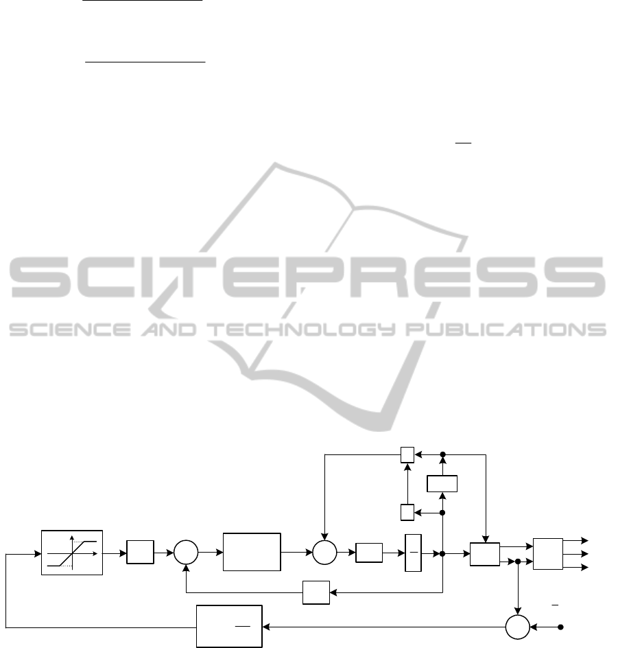
In this section of the paper, the control of the
satellite’s attitude will be achieved by means of the
complex system presented in Fig. 3a; the system is
mainly based on a control law with 2 components: a
proportional-integrator component with respect to the
quaternion vector (
q) and a proportional component
with respect to the satellite’s angular velocity vector
.
As the actuators’ system, we will use the cluster
(pyramidal configuration with four CMGs) presented
in the previous section; the actuators’ saturation will
be considered both from the generated gyroscopic
couples’ point of view and from the gyroscopic frame
angular velocities’ point of view. The structure of the
system for the calculation of the vector
(the vector
containing
the angular velocities of the CMGs’ frames)
is presented in Fig. 3b.
The command
c
M
(the command couple of the
system) may be associated to the gyroscopic couple
g
M
from equation (15); this equation becomes:
,KMK
c
(17)
modelled within the pyramidal cluster (Fig. 3b); for
the calculation of the angular velocity vector
,
c
we
use the equations (17) and (13); we get:
,K
Q
c
with
Q the pseudo-inverse of matrix
.QQ
The signal
c
is applied to the gyroscopic frames’
drive motors by means of the dynamic correction
filter having the transfer matrix:
.
s2s
s
44
2
000
2
2
0
IH
f
(18)
The vector of the satellite’s command moments is
.
Q
g
M
For satellite’s attitude control system
in Fig. 3, the following design equations are used:
,,, JkKkJJPkPKJkK
ddpppp
(19)
with (Lungu, 2008; Wie and Lu, 1995):
,
1
2,
2
2
2
i
nd
i
n
n
T
k
T
k
(20)
.
0
0
,diag
max
321 i
i
dpi
T
pppp
q
kkkkkk
q
(21)
From (19), one yields:
.
1
JkKP
p
(22)
For
,sat
*
Pq
L
with
,
321
T
LLLL
the limits
,3,1, iL
i
are calculated from the stabilized regime
condition (
u
c
=0). i.e.:
max
dp
KLK
or
,
max
dp
kLk
(23)
equation equivalent with the following one:
.3,1,
0
0
)21(
max
i
qk
k
L
i
i
pi
d
i
q
(24)
The satellite’s attitude (Euler angles –
,
and
) may be defined by means of two quaternion
vectors
(
T
qqq
321
q
and
T
qqqq
4321
ˆ
q
);
the significances of these angles are similar to the
ones expressing the attitude of an aircraft with respect
to the Earth tied frame: φ is associated to the roll
angle, θ – associated to the pitch angle and ψ –
associated to the direction angle. The differential
equations of the quaternions are (Heiberg et al., 2000):
;
2
1
,
2
1
2
1
44
qqq
T
qq
(25)
the correlation formulas between the components of
the quarternion vector
q
ˆ
and the satellite’s attitude
angles are (Wen and Delgado, 1991):
DeterminationandControloftheSatellites'AttitudebyusingaPyramidalConfigurationofFourControlMomentGyros
451
.
2
atan
,2asin
,
2
atan
2
4
2
3
2
2
2
1
4321
3241
2
4
2
3
2
2
2
1
4231
qqqq
qqqq
qqqq
qqqq
qqqq
(26)
For the calculation of the angular velocities’ vector
,
c
the pseudo-inverse of matrix Q must be obtained
first. From the methods for the calculation of the
pseudo-inverse, we can choose the robust type inverse
and the equation:
,
1
IQQQQ
TT
with I – the
identity
matrix. This formula does not always guarantee
the avoidance of single frame CMGs’ singularities.
Such a CMG can get into the singularity zone in the
presence of sensor noise. Furthermore, if the system is
controlled such that it goes into the singularity zone, it
can not escape from this state. Therefore, to remove
this drawback, we will use a simple but effective
equation for the calculation of the pseudo-inverse of
matrix Q (Wie et al., 2002; Haruhisa, 1997); it is
designed especially for reorientation maneuvers, stage
in which it is not necessary to achieve
certain accuracy.
The
pseudo-inverse is obtained by using the
formula (Wie et al., 2002; Haruhisa, 1997):
,E
1
TT
QQQQ
(27)
With
,0
1
1
1
E
12
13
23
(28)
where
i
is continuously modulated:
;3,1,sin
0
it
iii
(29)
this guarantees that
.0
Ku
QQ
k
This solution
does not ensure the avoidance of singularity, but
rather its proximity and transit.
qP
L
sat
L
L
s
1
(26)
q
4
q
(25)
0
0
0
q
*
qP
p
K
c
M
PYRAMIDAL
CLUSTER WITH
CMGs
d
K
s
1
1
i
T
P
1
J
J
(16)
J
J
(Fig. 3b)
g
M
a.
ICINCO2015-12thInternationalConferenceonInformaticsinControl,AutomationandRobotics
452
c
M
s
1
k
uK
K
(27)
Q
k
Q u
Q
E
(28)
(29)
0
i
Q
s
1
s
f
H
c
qP
L
sat
ci
L
ci
L
g
M
Q
g
M
b.
Figure 3: Satellite’s attitude control system using a pyramidal cluster with four CMGs (a) and a subsystem for the
calculation of the vector
(b).
4 NUMERICAL SIMULATION
RESULTS
In this section, the satellite’s attitude control system
(Fig. 3), using a cluster consisting of four CMGs (Fig.
1), is software implemented and validated in
Matlab/Simulink environment, for the case of a mini-
satellite. The attitude of the satellite (the angles
,
and
) will be controlled by means of the quaternion
vectors
(
T
qqq
321
q
and
T
qqqq
4321
ˆ
q
)
and of the gyroscopic moment
g
M
(the output signal
of the pyramidal cluster – Fig. 3b);
g
M
modifies the
vector of angular velocities
and the equivalent
kinetic moment vector
K; according to (11) and (13),
the modification of
K leads to the actualization of the
vectors
,
and of the matrix
;
Q
according to
(25), the modification of the vector
leads to other
expressions of the quaternion vectors (
q and q
ˆ
); the
modification of the quaternions is equivalent with the
change of the satellite’s attitude (see eq. (26)).
Let us consider the matrix of the satellite’s inertia
moments (Wie et al., 2002):
2
mkg
50005001800
5001.202100
180021004.21
J
(30)
and the values:
.s12,8.0,rad/s3
in
T
With
these,
we obtain
;88.4,8.18
d
kk
pi
k
is
calculated with (21) for
rad/s174.0deg/s10
max
i
and the quaternion
vector
T
qqqq 00000
ˆ
4321
q
.5454.05.05.045.0
T
Using (26) and (28), it results:
.
,
677.1677.1862.1
36.56690.4770-0.0049-
3.871341.49230.0460
0.06030.070336.9765
321
TT
LLLL
P
(31)
The nonlinearity
*
sat qP
L
is described by the
equation
,
~
,
,,
~
,
~
,
~
,
~
satsat
*
iii
iiii
iii
i
LL
LPL
LLPP
LPL
PPq
with
,3,1, iL
i
having the values in (31).
The limits of the saturation zone are chosen as:
.rad/s1111
4321
TT
ccccc
LLLLL
For the
transfer matrix H
f
(s) of form (18), we choose the
values:
,7.0,rad/s50
00
while, for the
cluster in Fig. 1, we consider
deg55
and the
initial vector
T
00000
4321
.2/2/2/2/
T
The matrix Q has the
form (23), with
4,1,Nms1000 iJK
gi
and
;Nms11110000000
TT
ZYX
KKK K
.deg/s0000000
321
TT
DeterminationandControloftheSatellites'AttitudebyusingaPyramidalConfigurationofFourControlMomentGyros
453

For the system presented in Fig. 3, we choose
(Wie et al., 2002):
.det10exp01.0
;,
2
,0,
2
sin01.0
321
T
ii
QQ
t
(32)
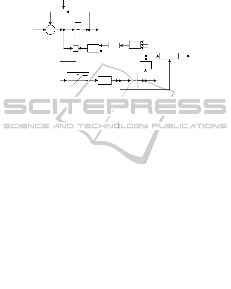
In Fig. 4a we present the time histories of the
satellite’s attitude angles (
,,
), angular velocities
321
,, , angular accelerations
,,,
321
components of the command couple of the system –
,,,
321 cccc
MMMM
components of the gyroscopic
moment –
321
,,
gggg
MMMM
and components of
the kinetic moment vector –
;,,
ZYX
KKKK
in
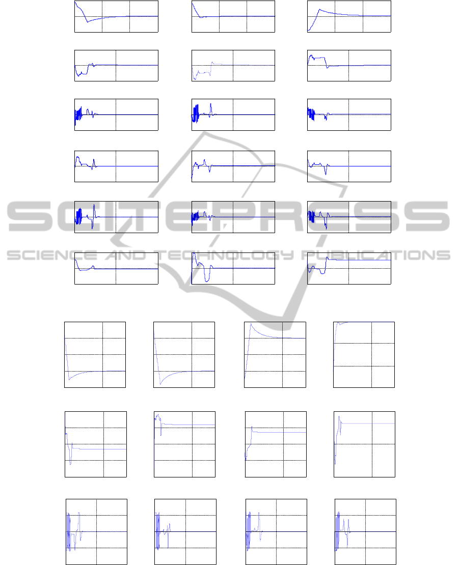
Fig. 4b we present the time histories associated to the
components of the quaternions
,,,,
ˆ
4321
qqqqq
to
the components of the vector
4321
,,,
and
the components of its derivative
.,,,
4321
As one can see in Fig. 3a, the control of the
satellite’s atitude is achieved by controlling the
quaternion vector
q and the satellite’s vector
.
Actually, the first component of the designed control
law
c
M
is proportional-integrator type and assures
the convergence of the quaternion vector
q to the
desired quaternion
T
000q
(see Fig. 4b); the
second component of the control law cancels the
deviation of the angular velocity vector from the one
associated to the reference frame (see Fig. 4a). The
closed loop control system has good convergence,
global asymptotically stability and
;0,0
ˆ
tt q
on the other hand, as one can notice from Fig. 4, the
cancel of the vectors
q
ˆ
and
leads to the cancel of
other variables: the components of the command
couple –
,,,
321 cccc
MMMM
the components of the
gyroscopic moment –
g
M
321
,,
ggg
MMM
and of
the kinetic moment vector –
.,,
ZYX
KKKK
ICINCO2015-12thInternationalConferenceonInformaticsinControl,AutomationandRobotics
454
0204060
-50
0
50
Time [s]
0204060
-100
0
100
Time [s]
0204060
-50
0
50
Time [s]
02040
-20
0
20
Time [s]
02040
-20
0
20
Time [s]
02040
-20
0
20
Time [s]
02040
-50
0
50
Time [s]
02040
-50
0
50
Time [s]
02040
-50
0
50
Time [s]
02040
-2000
0
2000
Time [s]
02040
-2000
0
2000
Time [s]
02040
-5000
0
5000
Time [s]
02040
-1000
0
1000
Time [s]
02040
-2000
0
2000
Time [s]
02040
-2000
0
2000
Time [s]
02040
-2000
0
2000
Time [s]
02040
1000
1500
2000
Time [s]
02040
-2000
0
2000
Time [s]
]d[ eg
[deg]
]d[ eg
]deg/s[
3
]mN[
1c
M
]deg/s[
2
1
]mN[
2c
M
]mN[
3c
M
]mN[
gX
M
]mN[
gY
M
]mN[
gZ
M
]smN[
X
K
]smN[
Y
K
]smN[
Z
K
]deg/s[
2
]deg/s[
1
]deg/s[
2
2
]deg/s[
2
3
a.
050
80
050
80
050
80
050
-0.2
0
0.2
0.4
0.6
Time [s]
050
-0.2
0
0.2
0.4
0.6
Time [s]
050
-0.6
-0.4
-0.2
0
0.2
Time [s]
050
0.4
0.6
0.8
1
Time [s]
-100
-50
0
50
100
Time [s]
-100
-80
-60
-40
-20
Time [s]
-150
-100
-50
0
50
Time [s]
0
50
100
Time [s]
02040
-100
-50
0
50
100
Time [s]
02040
-100
-50
0
50
100
Time [s]
02040
-100
-50
0
50
100
Time [s]
02040
-100
-50
0
50
100
Time [s]
80 80 80 80
1
q
2
q
3
q
4
q
]deg[
4
]deg/s[
1
050
80
]deg[
3
]deg[
2
]deg[
1
]deg/s[
2
]deg/s[
3
]deg/s[
4
b.
Figure 4: Time histories of the main variables associated to the satellite’s attitude control system.
DeterminationandControloftheSatellites'AttitudebyusingaPyramidalConfigurationofFourControlMomentGyros
455

5 CONCLUSIONS
The purpose of this study was to design a new
architecture for mini-satellites’ attitude control using a
cluster consisting of four CMGs and feedback from
the quaternion and angular velocity vectors; the
equivalent gyroscopic moment modifies the satellite’s
equivalent kinetic moment and the vector of angular
velocities, this leading
to the modification of the
satellite’s quaternion vector and of its attitude. The
new architecture has been software implemented and
validated through complex numerical simulations for
the case of a mini-satellite involved in a typical
motion around its own axis; the closed loop control
system has been proved to be characterized by con-
vergence and global asymptotically stability.
ACKNOWLEDGEMENTS
This work was supported by the project “Computa-
tional Methods in Scientific Investigation of Space”,
project no. 72/29.11.2013, of the Romanian National
Authority
for Scientific Research, Program for Research
- Space Technology and Advanced Research – STAR.
REFERENCES
Jovanovic, N., 2014. Aalto-2 satellite attitude control
system. Thesis of Master – Science in Technology.
Aalto University, School of Electical engineering.
Bouwmeester, J., Guo, J., 2010. Survey of worldwide pico-
and nano- satelitte missions, distributions and subsystem
technology. ActaAstronautica, vol. 67, pp. 854-862.
Lavet, V.F., 2010. Study of passive and active attitude
control systems for the OUFTI nanosatellites. Thesis
of Master – Engineering Physics. University of Liege,
Faculty of Applied Sciences.
Wie, B., Bailey, D., Heiberg, C., 2002. Rapid Multi-Target
Acquisition and Pointing Control of Agile Spacecraft.
Journal of Guidance, Control, and Dynamics, vol. 25,
no. 1, pp. 96-104.
Berner, R., 2005. Control Moment Gyro Actuator for Small
Satellite Applications. Thesis of Master of Science.
University of Stellenbosch, South Africa.
Lungu, M., 2008. Sisteme de conducere a zborului (Flight
control systems). Sitech Publisher, Craiova.
Ford, K.A., Hall, C.D., 2000. Singular Direction Avoidance
Steering for Control Moment Gyro. Journal of
Guidance, Control and Dynamics, vol. 23, no. 4, pp.
648-656.
Wie, B., Lu, J., 1995. Feedback Control Logic for
Spacecraft Eigenaxis Rotations Under Slew Rate and
Control Constraints. Journal of Guidance, Control and
Dynamics, vol. 18, no. 6, pp. 1372-1379.
Haruhisa, K., 1997. Constrained Steering Law of Pyramid-
Type Control Moment Gyros and Ground Tests.
Journal of Guidance, Control, and Dynamics, vol. 20,
no. 3, pp. 445-449.
Heiberg, C., Bailey, D., Wie, B., 2000. Precision Spacecraft
Pointing using Single-Gimbal Control Moment Gyros-
copes with Disturbances. Journal of Guidance, Control,
and Dynamics, vol. 23, no. 1, pp. 77-85.
Wen, J., Delgado, K., 1991. The Attitude Control Problem.
IEEE Transaction on Automatic Control, vol. 36, no.
10, 1148-1162.
ICINCO2015-12thInternationalConferenceonInformaticsinControl,AutomationandRobotics
456
