A Formal Specifiction for Conceptualizationsin Computer Aided
Visual Design Processes
Ewa Grabska
Faculty of Physics, Astronomy and Applied Computer Science, Jagiellonian University, 11 Łojasiewicza, Krakow, Poland
Keywords: Visual Design, Design Knowledge, Conceptualization, Ontological Commitment, Logical Language,
Ontology.
Abstract: The paper is the next attempt to formalize an ontology-based knowledge framework helpful for CAD pro-
cess. Our previous research has showed the need for a more expressive specification in order to capture the
intended models corresponding to a certain design conceptualization. This paper presents a more general
approach to ontological framework which will be illustrated with examples of designing floor-layouts. This
formal framework can be useful for many different applications, for instance to biological systems, cultural
heritage and economical aspects.
1 INTRODUCTION
This paper is an attempt to analyse conceptual de-
sign phase in Computer Aided Design (CAD) sys-
tem in the framework of computational ontology
.
Ontologies in computer science started to be-
come a relevant notion in the 1990’s. At that time
ontologies were related to work in knowledge acqui-
sition. From computer science point of view the
basic definition of an ontology is as follows: “An
ontology is an explicit specification of a conceptual-
ization”. In other words the ontology analyses rele-
vant entities and organizes them into concepts and
relations (Guarino et al., 2009).
Conceptualization is one of the most challenging
aspects of designing because it forces designers to
considers many disparate factors. There exists the
need to keep in mind objects, concepts, and other
entities that are assumed to exist in the considered
design domain of discourse, and the relationships
that hold among them. It is perhaps for this reason
drawing is such a popular tool of initial stages of
designer’s conceptualization. Drawings, being ex-
ternalization of designer’s conceptualization, are
seen as thinking aids (Suwa and Tversky, 1997). It
seems helpful if there exists a commitment between
the drawing and the level of certainty in the design-
er’s mind at the time. A CAD system communicates
with the designer via drawings displayed on the
monitor screen.
Nowadays, construction projects are commonly
represented in the Building Information Modelling
(BIM) to store all project 3D elements in a central
data-base and generate 2D drawings and 3D render-
ings (Eastman et al., 2008). However, during the
conceptual design phase most of these tools do not
use data structures to reflect the design knowledge
extracted from design drawings on the monitor
screen, although this knowledge provides a starting
point for design refinement (Lawson, 2001). The
importance of visualization in design was discussed
in (Visser, 2006), while visual conventions allowing
for man-machine interaction were described in
(Booch, et al. 2005). It turns out that referring to
ontological terminology the communication between
the designer and the computer can be improved
(Yurchyshyna and Zarli, 2009).
Besides CAD there exist many different applica-
tions based on ontologies. They are related for in-
stance to biological systems, cultural heritage and
economical aspects. This paper presents common
rational grounds for existence of different applica-
tions in the similar ontological framework. The
formal framework based on ontological terminology
will be illustrated with examples of designing floor-
layouts.
2 CONCEPTUALIZATIONS AND
OBSERVABLE WORLD STATES
A conceptualization is an abstract and simplified
Grabska, E..
A Formal Specifiction for Conceptualizationsin Computer Aided Visual Design Processes.
In Proceedings of the 7th International Joint Conference on Knowledge Discovery, Knowledge Engineering and Knowledge Management (IC3K 2015) - Volume 2: KEOD, pages 395-401
ISBN: 978-989-758-158-8
Copyright
c
2015 by SCITEPRESS – Science and Technology Publications, Lda. All rights reserved
395
view of the world created in a domain of discourse
that is a subset of some cognitive domain. In this
paper design aided by computer is our cognitive
domain, while designing floor-layout makes the
domain of discourse. Formally, we start with the
definition of conceptualization stated by Genesereth
and Nilsson (Genesereth and Nilsson, 1987).
Definition 2.1
A conceptualization is a tuple (D, R), where
D is a set called the universe of discourse, and
R is a set of relations on D.
Each element of R is an extensional relation, reflect-
ing a specific world state involving the elements of
D, such as one depicted in Fig. 1. In design aided by
computer we need to explicitly specify conceptual-
ization, while conceptualizations are typically im-
plicit in the mind of designer. In CAD system con-
ceptual process in designer’s mind is supported by a
cognitive tool, such as computer screen. There exists
many specialized editors for drawing floor layouts
on the monitor screen, where for instance a floor
layout is composed of polygons representing func-
tional areas or rooms (Grabska, 2011).
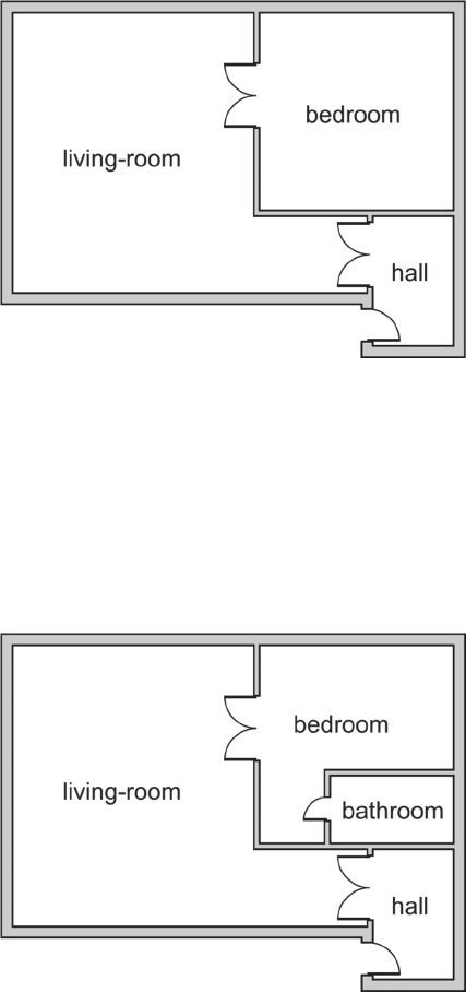
Example 2.1
Let assume that the designer visualizes an initial
drawing shown in Figure 1. We can extract the fol-
lowing knowledge that specifies the universe of
discourse and relations:
D = {room, wall, door} .
R = {bedroom, living-room, hall, adjacent- to,
accessible- to}.
A generalization/specialization hierarchy, i.e., a
taxonomy forms the backbone of an ontology. Then
room, bedroom, living room, hall might be relevant
concepts, where the first is a super-concepts of the
latter three. On the other side, we have a content
hierarchy a room consists of walls, a door is con-
tained in a wall. Relations of R can be defined be-
tween rooms:
adjacent-to = { (living room, bedroom), …}, acces-
sible-to = {…,(living room, bedroom)}.
The designer on the base of the conceptualization
can generate an observable world state. However,
this does not meet designer’s needs because it de-
pends too much on a specific state of the world. In
each step of design process the designer can change
number of elements of the domain of discourse D
and/or relations of R on D because both the require-
ments and the design become more refined as the
project proceeds.
Figure 1: The drawing reflecting a specific world state for
the conceptualization (D,R).
Example 2.2
Let assume that the designer on the base of the con-
ceptualization in Fig. 1 decides to divide the bed-
room into two rooms: bathroom and smaller bed-
room. Although only one room is added we obtain
the second conceptualization (see: Fig. 2),
Figure 2: Another world state for the concep-tualization
(D’,R’).
where D’ = D and R’ = R
{bathroom}
adja-
cent-to’
accessible-to’, where adjacent-to’ =
adjacent –to
{bathroom, (bedroom, bathroom),
(bathroom, hall), (bathroom, living room)}, and
accessible-to’ = accessible-to {bedroom, bath-
room}.
A conceptualization should not change when the
world changes. We need to focus on the meaning of
the underlying concepts, which are independent of a
single world state: the meaning of accessible to is
related to two rooms in the floor-layout. Understand-
KEOD 2015 - 7th International Conference on Knowledge Engineering and Ontology Development
396
ing such meaning implies having a rule to decide,
observing different patterns, whether or not there
exists a relation accessibility between two rooms.
Between rooms in an accessibility relation there
exists a door opening which can be with or without a
door. They are hundreds of different types of door.
Moreover, instead a door a curtain can be hung in
the door opening. In most cases this is impossible to
list all elements of the relation, which are independ-
ent of a single world state.
The meaning of “accessibility” can be defined as
a function that, for each global context involving all
our universe, gives us the list of pairs of accessible
rooms. The revers of this function grounds the
meaning of a concept in a specific world state. Link-
ing this with conceptualization we define a function
from a set of possible world states into extensional
relations. To formalize this function, we first have to
clarify what a world and a world state is. In the
stage of conceptual process aided by computer when
the conceptualisation is formed in the mind of de-
signer he/she try to externalize own concepts using
drawings. In other words initial solutions in the form
drawings being observable states of affairs constitute
states of designer’s world. In this paper to represent
the world state, the concept of visual site will be
used (Shimojima, 1996). A visual site is a drawing
along with a surface on which it is drawn. In general
different surfaces can be used for drawing, e.g., a
sheet of paper or a monitor screen. Two different
drawings on the same surface determine two differ-
ent visual sites. In visual design aided by computer,
monitor screen is a basic visual site on which be-
sides drawing some information from computer
system can be generated (Grabska, 2014).
Each designer generates his/her own world. Ob-
servable states of the world should be defined with
the reference to the notion of a design space S, i.e., a
piece of reality we want to model. In our case the
design space will be all configurations of rooms with
its components such as walls, doors, etc., which can
be treated as admissible floor-layouts.
Definition 2.2
A world is an ordered set of world states, corre-
sponding to the evolution of the design space in
time.
Definition 2.3
Let S be a design space, D an arbitrary set of distin-
guished elements of S, and W the set of possible
states for S. The tuple (D, W) is called a domain
space for S.
A conceptual relation
n
of arity n
1 defined for a
domain space (D, W) is a function
n
:W →
P
(D
n
)
from the set W into the family of all subsets of the set
of n-ary relations on D.
A conceptual relation is a function from a set of
possible world states into extensional relations. This
function allows one to extend the notion of concep-
tualization for all observable world states (Guarino
et al., 2009).
Definition 2.4
A conceptualization for W is a triple
C =
(D, W, R ),
where
D is a domain of discourse,
W is a set of world states, and
R
= {
n
}
n
1
is a family of all conceptual rela-
tions
n
on the domain space (D, W)
3 MODELS IN ONTOLOGY
In practical applications we use a language to de-
scribe the elements of a conceptualization. For in-
stance, accessible to is a predicate symbol which
expresses the fact that bathroom is accessible to
bedroom. The symbol represents a certain conceptu-
al relation. Our language denoted by L should com-
mit to a conceptualization. Let assume that L is a
first-order logical language with its vocabulary as
the set {bathroom, bedroom, living room, hall, ac-
cessible-to, adjacent-to}. We shall not consider
function symbols here.
The basic problem is to interpret each symbol
according to the conceptualization we commit to. It
turns out that the vocabulary can be interpreted in
many different ways even if the cognitive domain
and its subset – the domain of discourse were fixed.
A conceptualization is specified in two ways: exten-
sionally and intensionally. An extensional specifica-
tion of the conceptualization requires listing the
extensions of every conceptual relation for all possi-
ble worlds. However, it is impossible if the universe
of discourse D or the set W of possible states of
world are infinite. A conceptualization is often spec-
ified by means of examples related to selected world
states. A more effective way to specify a conceptual-
izations is to fix a language and to constrain its in-
terpretation in an intensional way, by means of axi-
oms called meaning postulates. For our example, we
can write simple axioms stating that accessible-to is
symmetric, irreflexive, and transitive, while adja-
cent-to is symmetric, irreflexive and intransitive.
A Formal Specifiction for Conceptualizationsin Computer Aided Visual Design Processes
397
According to (Guarino et al., 2009) the notion of
ontology can be tentatively defined in the following
way: An ontology is a set of axioms, i.e., a logical
theory designed in order to capture the intended
models corresponding to a certain conceptualization
and to exclude the unintended ones.
In other words we have to deal with an approxi-
mate specification of a conceptualization: the better
intended models will be captured and non-intended
models will be excluded.
Now when we have an intuitive grasp of ontolog-
ical commitment and ontology, let us embed them in
a more formal framework. We start with the defini-
tion of model.
Definition 3.1
Let L be a first order logical language with vocabu-
lary V and (D,R) be a conceptualization. A model
for L is a triple M = ( D,R, I ), where I: V
D
R
is an interpretation function that maps each symbol
of V to either an element of D or a relation belong-
ing to R.
Let us consider the model shown in Fig. 1. We can
assign suitable rooms depicted in the Fig. 1 to sym-
bols bathroom, bedroom, living room, and hall. The
two symbol relations accessible-to and adjacent-to
are defined by listing all suitable pairs of rooms.
Two rooms are adjacent if they have at least one
common wall, while room1 is accessible to room2 if
there exists a common wall with door. Wall and
door are represented by a segment and door icon,
respectively.
Definition 3.2
Let L be a first-order logical language with vocabu-
lary V and C = (D,W,R) be a conceptualization for
W. An ontological commitment for L is a tuple K =
(C, I ) where
I
:
V
D
R
that maps each vocabulary symbol of
V to either D or a conceptual relation belonging to
the set R
.
The notion of ontological commitment is an exten-
sion of the standard notion of model to intensional
meaning. Now we can define a notion of intended
models corresponding to a certain conceptualization.
As it has been considered capturing these models is
the biggest challenge in ontology.
Definition 3.3
Let C = (D,W,R) be a conceptualization for W, L be
a first-order logical language with vocabulary V
and ontological commitment K = (C, I).
A model M = (D, R, I) is called an intended model
of L according to K iff
1. For all constant symbols c
V we have I(c)= I
(c),
2. There exists a world w
W such that, for each
predicate symbol v
V there exists an inten-
sional relation
R
such that I(v) =
and I(v)
=
(w).
For intended model the mapping of constant sym-
bols to elements of universe of discourse is the same
for I and I
and there must exists a world such that
every predicate symbol is mapped into an intension-
al relation whose value, for that world, coincides
with the extensional interpretation of this symbol.
The set I
K
(L) of all models of L that are compatible
with K is called the set of intended models of L ac-
cording to K.
Finally, the next tentative definitions of ontology
is proposed (Guarino et al., 2009):
Definition 3.4
Let C be a conceptualization for W, and L a logical
language with vocabulary V and ontological com-
mitment K. An ontology O
K
for C with vocabulary V
and ontological commitment K is a logical theory
consisting of a set of formulas of L, designed so that
the set of its models approximate as well as possible
the set of intended of L according to K.
Example 3.1
We build an ontology O for floor-layout design,
which consists of a set of logical formulae. Floor-
layout domain is specified with increasing precision.
Taxonomic Information:
O
1
= { living room(x) room(x), bedroom(x)
room(x), …}
Domains and Ranges of Relations:
O
2
= O
1
{accessible-to(x,y)
room(x)room(y),…}
Symmetry:
O
3
= O
2
{accessible-to(x,y) accessible-
to(y,x), …}
4 ONTOLOGIES IN CAD SYSTEMS
When considering ontologies in computer science
the conceptualization should be expressed in a for-
mal machine readable format. In design aided by
knowledge based computer system we need to make
knowledge representation extracted from conceptu-
KEOD 2015 - 7th International Conference on Knowledge Engineering and Ontology Development
398
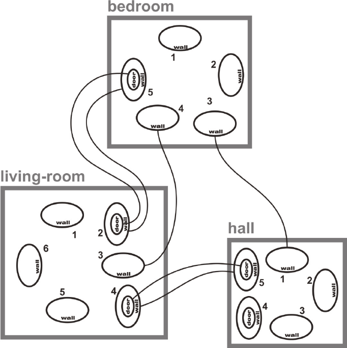
Figure 3: A B-graph representing the world state in Fig. 1.
alization: accessible electronically; structured and
understandable by computers, interoperable, and
transparent. Graphs can be combined with the most
popular logic-based knowledge representation tech-
nique, where knowledge is represented explicitly by
symbolic terms and reasoning is the manipulation of
these terms. Graph data structures are used to reflect
the design knowledge extracted from design draw-
ings on the monitor screen. This knowledge provides
a starting point for design refinement.
There exist many types of graphs useful for spec-
ification and modelling of design knowledge during
conceptualization in CAD processes. In this paper
we use a specific graphs called B-graphs whose
nodes represent objects of the domain of discourse.
Their nodes contain bonds which are also nodes
representing arguments of relations. Relations are
defined between bonds (Grabska 1994). Two kinds
of bonds are distinguished: engaged and free bonds
which correspond to arguments of existing and po-
tential relations, respectively. B-graphs are content-
hierarchical. Hierarchy also allows for sub-bonds
(for example, a room consists of walls and one of
them has a door – this door is contained in the room,
but also is subordinate to the wall).
The Fig. 3 presents the B-graph corresponding to
the drawing considered in Example 2.1. Three nodes
represent three rooms. The number of walls of room
determines the number of bonds representing them.
If the wall has a door then the bond representing the
door is contained in the wall bond. An edge between
the door bonds represents the accessibility relation,
while between the wall bonds – adjacency one. The
walls of each room shown in Fig. 1 can be ordered
clock-wise starting from the top left –most one. The
distinct of bonds is essential in definitions of opera-
tions on graphs that reflect modifications of design
phases (compare: Fig. 3 with Fig. 4).
The B-graphs shown in Fig. 3 and Fig. 4 can be
treated as internal representations for the drawings
created on the monitor by the designer and shown in
Fig. 1 and Fig. 2. These drawings reflect the results
of some phases of designer’s conceptualization
while B-graphs corresponding to them determine
A Formal Specifiction for Conceptualizationsin Computer Aided Visual Design Processes
399
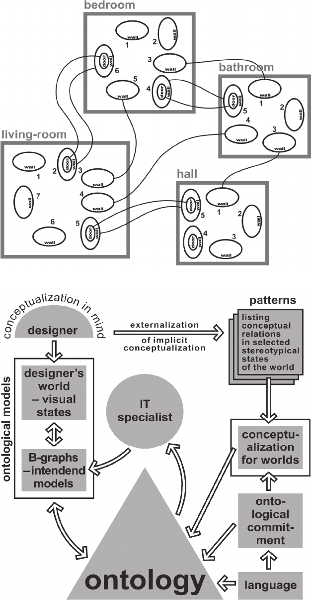
Figure 4: The B-graph for the drawing in Fig. 2.
Figure 5: The relationships between designer’s conceptualization, the formal conceptualization for worlds, the logical lan-
guage used to describe ontology, the IT specialist, and ontological intended models.
KEOD 2015 - 7th International Conference on Knowledge Engineering and Ontology Development
400
elements of the graph based data structure. B-graphs
are specified by the IT specialist.
The presented approach allows to define formal-
ly correspondence between drawings and B-graphs
in the framework of ontology. The B-graph in Fig.3
reflects a world state shown in Fig. 1. The visual site
with drawing presented in Fig.1 and the B-graph in
Fig. 3 belong to the set of intended models of L
according to the same ontological commitment K.
The summary of our consideration is shown in
Fig 5.
5 CONCLUSIONS
Within architectural design, key aspects of the antic-
ipated function of buildings are determined by their
structural form, i.e., their shape, layout, or connec-
tivity. The formal modelling of structural form for
CAD systems remains elusive. The structural form
emerges during the conceptual design phase.
This paper has presented the practical concerns
surrounding the formal interpretations of the struc-
tural form with respect to its applicability in CAD
systems in the ontological framework. The basic
notions of ontology: conceptualizations, models,
ontological commitments, and intended models have
been defined in a formal way.
One of the challenges of CAD systems is to au-
tomatically transform design drawings on the moni-
tor screen into appropriate graph based date struc-
tures. The framework of ontology proposed in this
paper allows to define the correspondence between
the drawings and their graphs in a formal way. This
formal approach to the definition of ontology facili-
tates the development of reasoning modules of CAD
system which are based on graph data structure.
Thanks to this, dialogue between the designer and
computer can be improved.
REFERENCES
Guarino, N. et al., 2009. What Is an Ontology. Handbook
on Ontologies. Springer, Heildelberg.
Suwa, M., Tversky, B., 1997. What architects and students
perceive in their sketches: A protocol analysis. In De-
sign Studies 18, pp. 385–403.
Eastman, Ch. et al., 2008. BIM Handbook: A Guide to
Building Information Modeling for Owners Managers,
Designers, Engineers and Contractors, Wiley.
Lawson, B., 2001, How designers think, Architectural
Press.
Visser, W., 2006. The cognitive artifacts of designing,
Erlbaum L. Associates, Mahwah, NJ.
Booch, G. et al., 2005. The unified modeling language
user guide. Addison-Wesley, NJ.
Yurchyshyna, A., Zarli, A., 2009. An Ontology-based
Approach for Formalisation and Semantic Organiza-
tion of Conformance Requirements in Construction. In
International Research Journal Automation in Con-
struction. Volume 18. Issue 8, pp. 1084-1098.
Genesereth M. R., Nilsson N. J., 1987. Logical Founda-
tion of Artificial Intelligence. Morgan Kaufmann. Los
Altos. CA.
Grabska, E., 2011. Computer Aided Conceptual Visual
Design based on Ontology, In KEOD 2011, 3
rd
Inter-
national Conference on Knowledge Engineering and
Ontology Development, pp. 396-399.
Shimojima, A., 1996. Operational Constraints in Diagram-
matic Reasoning. In Logical Reasoning with Dia-
grams. Oxford University Press, pp. 27–48.
Grabska, E., 2014. An Ontology based Approach for
Assisting Conceptualisation in CAD Processes. In
KEOD 2014, 6
th
International Conference on
Knowledge Engineering and Ontology Development,
pp. 272-279.
Grabska, E. (1994) Graphs and Designing, In Schneider,
H.J., Ehrig, H., eds., Graphs Transformations in Com-
puter Science, Springer Verlag, Berlin Heidelberg,
1994.
A Formal Specifiction for Conceptualizationsin Computer Aided Visual Design Processes
401
