
Cognitive Radio Management Benefiting from Flexible
Reconfiguration
Xiguang Wu, Jacques Palicot and Pierre Leray
CentraleSupélec / IETR
Avenue de la Boulaie CS 47601, F-35576 Cesson-Sevigné CEDEX, France
{xiguang.wu, jacques.palicot, pierre.leray}@centralesupelec.fr
Keywords: Cognitive Radio, Dynamic Partial Reconfiguration, FPGA, Zynq, Management.
Abstract: Cognitive Radio (CR) has the ability to adapt its behavior to the changing environment. In order to achieve
this goal in real practice, a CR equipment should be able to manage and reconfigure itself flexibly and
efficiently. Therefore, it is necessary to integrate management in the CR equipment. Benefiting from the
dynamic full and partial reconfiguration, Zynq based devices provide more flexible features and become a
preferable hardware platform for CR. In this paper, we briefly introduce the cognitive radio management on
a Zynq based platform, and study the benefit and cost of offloading computations from software to hardware.
The results show that it is possible to win both performance and power consumption by flexible
reconfiguration.
1 INTRODUCTION
As the digital communication systems evolve from
GSM and now toward 5G, the supported standards
are also growing. The desired communication
equipments are required to support different
standards in a single device at the same time. The
software defined radio (SDR) (Mitola, 1995) has
been considered a solution to this requirement,
because typical way to change the function of a
communication equipment needs to redesign the
hardware. By using the SDR, the function of the
communication equipment can be changed by
software reprogramming without modifying the
hardware.
Furthermore, Cognitive Radio (CR) (Mitola,
2000) has been proposed to integrate new
capabilities, which can automatically adapt its
behavior to the changing environment. But more is
expected, in order to efficiently manage the CR
features, we introduce a management architecture,
namely Hierarchical and Distributed Cognitive
Radio Architecture Management (HDCRAM)
(Godard, Moy and Palicot, 2006), which has been
proposed for CR management by our team.
In order to design CR equipments, flexible and
efficiently reconfigurable hardware platforms are
necessary. Zynq based platform becomes a favorable
choice because it integrates ARM processor and
FPGA in a single device (Xilinx, Inc., 2013, UG585),
which provides both flexibility and performance.
Especially, it enables dynamic full and Partial
Reconfiguration (PR) (Xilinx, Inc., 2010, UG702).
Benefiting from these features, Zynq based device is
more suitable for developing CR equipment.
CR has also been considered as an enabling
technology for green radio communications (Palicot,
2009). In this paper, we investigate the performance
and power consumption taking the software and
hardware FIR filter as a study case on Zynq based
ZC702 evaluation board. The results provide the
useful information for the management of the FIR
filter, and with the HDCRAM, it is possible to
benefit both performance and power consumption
from flexible full and partial reconfiguration.
2 HDCRAM ARCHITECTURE
2.1 Introduction
A radio equipment consists of a set of functional
components that are connected with each other,
illustrated as processing elements (PEs) at the
bottom of Figure 1. These PEs can either be
software or hardware elements.
18
Wu X., Palicot J. and Leray P.
Cognitive Radio Management Benefiting from Flexible Reconfiguration.
DOI: 10.5220/0005888800180023
In Proceedings of the Fourth International Conference on Telecommunications and Remote Sensing (ICTRS 2015), pages 18-23
ISBN: 978-989-758-152-6
Copyright
c
2015 by SCITEPRESS – Science and Technology Publications, Lda. All rights reserved
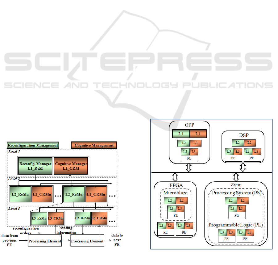
Figure 1: An example of HDCRAM.
Figure 2: An example of HDCRAM deployment.
Our team has proposed a management
architecture for Cognitive Radio in a previous work,
namely HDCRAM (Palicot, 2013). A diagram of
HDCRAM architecture featuring three levels is
depicted in Figure 1.
HDCRAM consists of two aspects: Cognitive
Radio Management (CRM) and Reconfiguration
Management (ReM). The CRM part is responsible
for gathering sensing information and making
decisions according to the information obtained
from PEs. The ReM part is in charge of taking
actions to reconfigure the system. It takes a bottom-
up approach in the CRM part. Sensing information
is submitted from the lower level to the upper level.
When a CRM unit has made a reconfiguration
decision, it sends the reconfiguration parameters to
its associated ReM unit at the same level. It uses a
top-down method in the ReM part. The
reconfiguration commands are sent from the upper
level to the lower level.
HDCRAM is composed of three hierarchy levels.
At level 1, only one cognitive radio manager and
one reconfiguration manager can exist, because this
is the top level. At level 2 and level 3, there are
multiple couples of Cognitive Radio Management
units (CRMu) and their associated Reconfiguration
Management units (ReMu).
The architecture featuring three levels is
sufficient. The level 1 manages the exchange of
different standards; the level 2 manages the
reconfiguration of the middle scale functions; and
the level 3 manages the PEs.
According to this hierarchical management, a
cognitive cycle can be on three different scales: 1) a
local small cycle, in which the sensing, decision
making, and reconfiguration action are processed,
only includes the PE and its associated level 3
management; 2) a medium cycle that involves
multiple PEs and a level 2 management, the
reconfiguration of a PE needs the cooperation with
other PEs; 3) or a large cycle that concerns all the
three levels of management.
2.2 Deployment Example
There may be many different choices to deploy
HDCRAM. In this section, we only take one
possible HDCRAM deployment method as an
example, to introduce the deployment of HDCRAM,
as shown in Figure 2.
It comprises a GPP, a DSP, a FPGA, and a Zynq
based device. A straightforward way is placing the
level 1 manager on the GPP, and maybe multiple
level 2 and level 3 management units on it. A level 2
management unit and multiple level 3 management
units are deployed on DSP, FPGA, as well as Zynq.
An embedded processing core Microblaze is
employed on the FPGA with the level 2
management unit on it. A PE may be hardware in
logic or software on Microblaze. Therefore, a level 3
management unit that is in charge of managing a PE
may also be hardware or software, or part of it is
software executed on Microblaze and another part is
hardware. On Zynq, similar to the PFGA, a level 2
management unit is on PS, and a PE may also either
be hardware on programmable logic (PL) or
software on processing system (PS). A level 3
management unit may also be hardware or software,
or part of it is software executed on PS and another
part is hardware on PL.
Cognitive Radio Management Benefiting from Flexible Reconfiguration
19
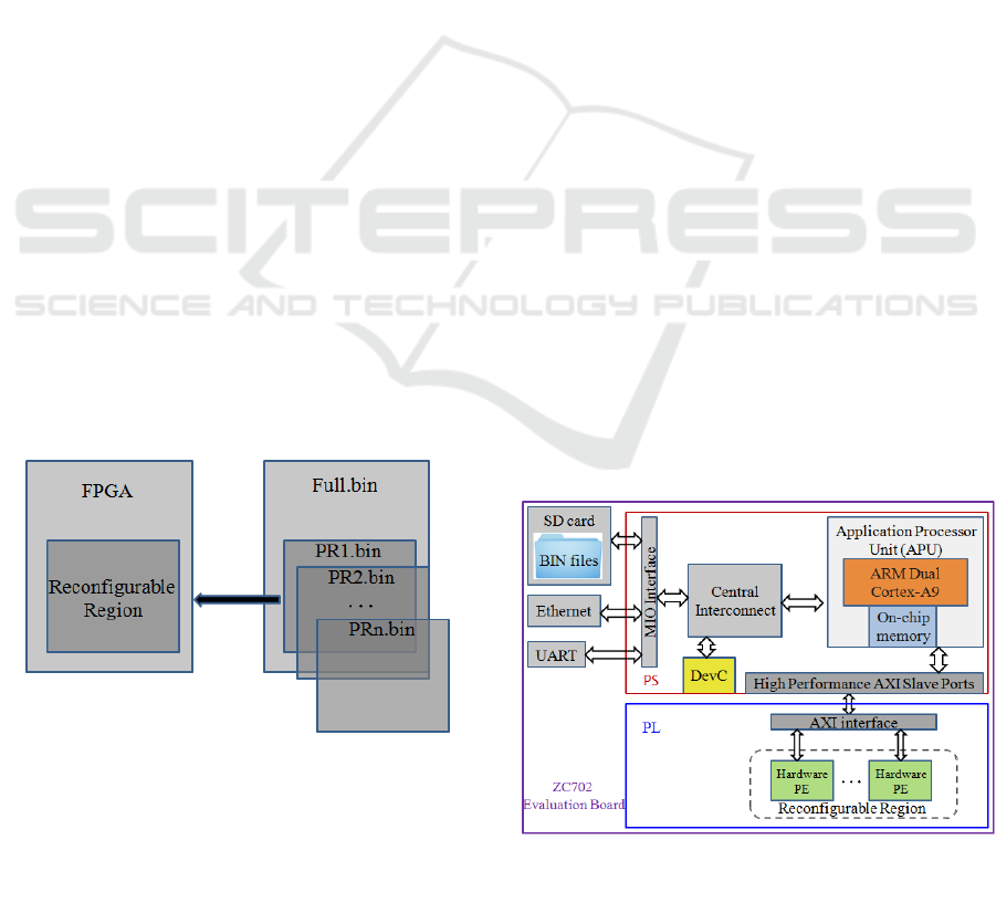
Figure 4: A simplified architecture of the ZC702
evaluation board.
3 DYNAMIC PARTIAL
RECONFIGURATION
3.1 Introduction
FPGA devices have provided the flexibility to do
on-site device reprogramming, but a drawback of
traditional FPGA is that it has to stop running and
reprogram the entire logic even if a very small part
of the logic needs to be updated. Recently, some
FPGA families have provided a Dynamic Partial
Reconfiguration (DPR) technique, which extends the
inherent flexibility of the traditional FPGA. DPR
allows designers to change the functionality of
specific regions in an operating FPGA by
dynamically downloading a partial configuration
bitstream while the remaining logic continues to
operate without interruption.
The logic in the FPGA design is divided into two
different types, reconfigurable logic and static logic.
Reconfigurable logic is any logical element that is
part of a reconfigurable region. These logical
elements are modified when a partial bitstream is
loaded. Static logic is any logical element that is not
part of a reconfigurable region. These logical
elements are never partially reconfigured and always
active when a partial bitstream is loaded (Xilinx,
Inc., 2010, UG702).
As shown in Figure 3, the block portion labeled
Reconfigurable Region represents reconfigurable
logic and the light gray area of the FPGA block
represents static logic. The function implemented in
Reconfigurable Region is modified by downloading
one of several available partial BIN files, PR1.bin,
PR2.bin, PRn.bin, etc.
Figure 3: Reconfigurable logic and static logic.
There are many reasons why the DPR is
advantageous over traditional full configuration.
Flexibility. The functionality of part of the
FPGA can be updated at any time by locally
or remotely loading the partial bitstream that
is needed on the fly, which makes the
hardware software-like.
Reduce reconfiguration time. Because a
partial bitstream is smaller than the full
bitstream, and the configuration time is
proportional to the size of the bitstream, the
reconfiguration time of DPR is shorter.
Especially when the partial bitstream is quite
small, compared with the reconfiguration of
the entire device, DPR can significantly
reduce the reconfiguration time, which is quite
useful to applications requiring strict timing
constraints.
Improve performance. Only a portion of the
device is reconfigured, the static logic remains
functioning and is completely unaffected by
the loading of a partial BIN file. There is no
need to stop running and reprogram the entire
device, therefore, it does not affect the
performance of the rest of the device.
Hardware sharing. DPR can realize the
hardware reuse, which enables different
functionalities to be implemented in the same
portion of the device.
Save space and resources. By taking
advantage of the DPR, the same system can be
implemented in smaller devices featuring less
resource thus reducing the size of the FPGA.
Consequently, reduce power consumption and
overall cost.
3.2 Full and Partial Reconfiguration on
Zynq
The ZC702 evaluation board utilizes a Xilinx Zynq-
7000 All Programmable SoC (AP SoC), which
Fourth International Conference on Telecommunications and Remote Sensing
20
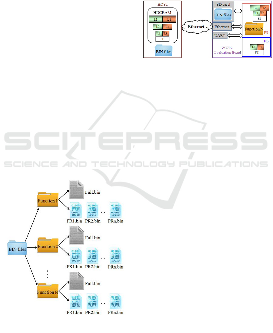
Figure 5: The storage organization of the reconfiguration
bitstreams.
integrates a dual-core ARM Cortex-A9 as the
processing system (PS) and a Xilinx’s 7 series
FPGA Artix-7 as the programmable logic (PL) in a
single device (Xilinx, Inc., 2013, UG850).
On Zynq, there are two ways for DPR to
reconfigure the PL, i.e., either by the internal
configuration access port (ICAP) primitive in the PL,
or through the device configuration (DevC) /
processor configuration access port (PCAP)
interface in the PS (Christian Kohn, 2013).
ICAP can only perform partial reconfiguration in
the PL, but PCAP supports both full and partial
reconfiguration of the PL from the PS, which
provides more flexibilities. Furthermore, the
bitstreams are transferred to the PCAP interface by a
Direct Memory Access (DMA) approach, which
frees the processor to execute other tasks. Therefore,
we utilize the PCAP method.
Different functions can be designed to share the
hardware PL by dynamic full and partial
reconfiguration in the field. The generated full and
partial bitstreams can be stored in a database. Each
function has a full bitstream and several partial
bitstreams depending on the real needs. Figure 5
illustrates the storage organization of the BIN files
database.
The reconfiguration bitstreams are stored in the
database on the host computer. The full or partial
bitstreams can be remotely downloaded through
Ethernet to change the functionality of the complete
or pre-defined regions of PL on the fly as needed.
They can also be stored on the SD card on the
ZC702 evaluation board if the level 2 management
works standalone. It is also possible to dynamically
download new full and partial bitstreams through
Ethernet to update the database. Some partial
bitstreams are able to be read into the on-chip
memory in PS if they are frequently used.
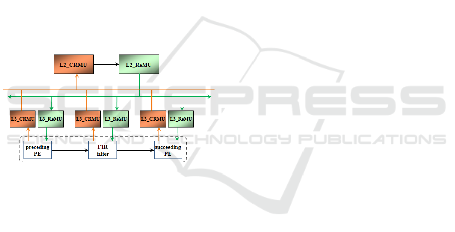
Figure 6: The HDCRAM implementation on the
ZC702 evaluation board.
4 CASE STUDY
A finite impulse response (FIR) filter is a commonly
used processing element in digital signal processing.
It could be implemented either in software mapped
onto the PS or in hardware mapped onto PL.
Therefore, we would like to investigate the benefit
and cost of the FIR filter implementation on PS and
PL respectively, and then the results will provide
helpful information for CRMu to make an
appropriate decision.
4.1 Evaluation of performance and
power consumption of FIR filter
implementations
Take a 32-tap FIR filter as an example, which is
implemented on PS and on PL respectively. The
operations are executed in serial on PS, but on PL,
the FIR filter could be implemented in serial or in
parallel.
And the hardware serial and parallel
implementations of the FIR filter reuse the PL logic
by taking advantage of the PR. After generating the
full and partial bitstreams for the PL following the
PR design flow, we store them in the database on the
host as shown in Figure 7. A blank full bitstream is
also generated to clear the PL to save power if the
PL part is not needed, which is stored in NOPL
folder. Table 1 shows the resource available in the
reconfigurable region and used by the FIR filter. The
serial implementation consumes less resource, and it
uses 2 DSP48E1s, which is 32 times less than the
Cognitive Radio Management Benefiting from Flexible Reconfiguration
21

Figure 8: Power consumption of PS.
Table 3: Power consumption of PL.
Function
NOPL
Serial
Parallel
Power(W)
0.06
0.095
0.101
parallel implementation. But the serial way
consumes more memory than the parallel approach.
Figure 7: The full and partial bitstreams of the design.
Table 1: Resources available and used by the FIR filter.
Resource
Available
Serial
Parallel
LUT
10304
868
1096
FD_LD
20608
1516
3108
SLICEL
1564
141
288
SLICEM
1012
91
187
DSP48E1
72
2
64
RAMBFIFO36E1
36
8
4
The timing overhead of full and partial
reconfiguration should also be considered. Because
downloading a bitstream remotely from the host
computer consumes longer time than that from the
local memory, if we can benefit from remote
reconfiguration, undoubtedly we can also benefit
from local reconfiguration. The sizes of full and
partial bitstreams, and the time consumed of remote
full and partial configuration are listed in Table 2.
Table 2: Full and partial configuration time.
Type
Size (bytes)
Time (μs)
Full
4 045 564
215 736
Partial
707 712
51 865
We have also measured the power consumption
of both PS and PL. The most convenient and
simplest way to monitor the power consumption on
ZC702 board is to use Texas Instruments' (TI)
Fusion Digital Power Designer, which is a Graphical
User Interface (GUI) used to monitor and display the
real-time voltage and current of selected power rails
of the board (Xilinx, Inc., 2013, UG850). Table 3
lists the power consumption of PL for blank design
and the FIR filter.
In order to clearly and visibly observe the results,
we have sent amount of data to the implemented
software and hardware FIR filter. Each time we sent
4096 32-bit integers and then repeat 2000 times.
When the hardware approach is chosen, the data are
transferred between PS and PL by DMA approach.
Table 4 gives the total time consumed by software
and hardware implementations of the FIR filter.
Table 4: Execution time of the FIR filter.
Software
(μs)
Hardware (μs)
Serial
Parallel
12 229 279
281 315
279 026
We can see that although the hardware
approaches consume much less time than the
software way, the hardware parallel implementation
is not as fast as expected more than 32 times faster
than the serial implementation, which is because the
overhead of data transmission between PS and PL. It
takes some time when the data and commands are
transmitted from user space to Linux driver and then
to the hardware. Therefore, if only offloading the
FIR filter from the PS onto the PL, it is better to
choose the serial implementation, which occupies
less resource and consumes less power while not
losing much performance.
The reason why we repeat 2000 times is that we
cannot catch the power changes by TI Fusion Digital
Power Designer when the execution time is too short.
And even so, sometimes we still cannot catch PR
and hardware FIR filter operations. For the sake of
comparison and analysis, we put the operations of
software FIR filter, PR, and hardware FIR filter
together in Figure 8. At time 41:00, the software FIR
filter are started execution, at around 41:25 PR is
performed to reconfigure the PL, and at time 41:36,
the hardware FIR filter operations are executed. The
power risings at around 41:25 and at 41:36 are
because the data transmission from PS to PL. We
can see that the power increases from 0.33W to
0.44W during software FIR filter operations, which
lasts about 12.23s. But the additional power increase
Fourth International Conference on Telecommunications and Remote Sensing
22
of the hardware serial and parallel implementations
is around 0.04W on PL, which is less than 0.11W on
PS.
4.2 Management of FIR filter by
HDCRAM
Based on the above results, it is possible to benefit
both performance and power consumption by
offloading the FIR filter from the PS onto the PL.
Another advantage is that it frees the PS to execute
other tasks.
Therefore, we choose to implement the level 3
management of the FIR filter on the PS. The
L2_CRMu makes the decision to implement the FIR
filter on PS or on PL in serial or in parallel based on
the information obtained from other L3_CRMus.
And then the L2_ReMu sends the corresponding
reconfiguration command to the L3_ReMu of the
FIR filter, who then maps the FIR filter onto PS by
calling the software FIR filter function or onto PL by
dynamic full or partial reconfiguration.
Figure 9: Management of FIR filter.
If the PL is occupied by other computation
intensive PEs and has no more space for the FIR
filter, there is no choice and the L2_CRMu decides
to implement the FIR filter in software on PS, which
consumes 0.11W more power and has a longer
execution time.
Else if the preceding PE and the succeeding PE
of the FIR filter is implemented on PS, the
L2_CRMu decides to implement the FIR filter on
PL in serial mode, because it uses less resource with
additional 0.035W power consumption and the
performance is close to the parallel way (see Table 4)
due to the overhead of data transmission between PS
and PL.
Else if the preceding PE or the succeeding PE of
the FIR filter is implemented on PL, the L2_CRMu
decides to implement the FIR filter on PL in parallel
mode, because the speed is more than 32 times faster
than the serial way and the data transmission is in
hardware, which does not slow down the data
processing. This way consumes 0.041W more power
but has a higher performance.
5 CONCLUSIONS
In order to efficiently manage the CR features, it is
necessary to integrate management into CR
equipment. In this paper, we have briefly introduced
the HDCRAM architecture as well as partial
reconfiguration on Zynq. We have studied the
commonly used FIR filter and the benefit and cost
when it is implemented in PS and PL. The results
show that we can win both performance and power
consumption by flexible full and partial
reconfiguration, which also provide useful
information for the HDCRAM to make appropriate
decisions to efficiently manage the FIR filter
implementation. This also provides a reference to
the implementation of potential green scenarios,
which are our future works.
REFERENCES
Mitola, J. (1995). The software radio architecture.
Communications Magazine, IEEE, 33(5), 26-38.
Mitola, J. (2000). Cognitive Radio---An Integrated Agent
Architecture for Software Defined Radio.
Godard, L., Moy, C., & Palicot, J. (2006, June). From a
configuration management to a cognitive radio
management of SDR systems. In Cognitive Radio
Oriented Wireless Networks and Communications,
2006. 1st International Conference on (pp. 1-5). IEEE.
Xilinx, Inc. (2013, September). Zynq-7000 all
programmable SoC. Technical Reference Manual,
UG585 (v1.6.1),.
Xilinx, Inc. (2010, April). Partial Reconfiguration User
Guide. UG702 (v12.3).
Palicot, J. (2009, June). Cognitive radio: an enabling
technology for the green radio communications
concept. In Proceedings of the 2009 International
Conference on Wireless Communications and Mobile
Computing: Connecting the World Wirelessly (pp.
489-494). ACM.
Palicot, J. (Ed.). (2013). Radio engineering: From
software radio to cognitive radio. John Wiley & Sons.
Xilinx, Inc., (2013, April). ZC702 Evaluation Board for
the Zynq-7000 XC7Z020 All Programmable SoC User
Guide, UG850 (v1.2).
Christian Kohn, (2013). Partial Reconfiguration of a
Hardware Accelerator on Zynq-7000 All
Programmable SoC Devices. XAPP1159 (v1.0).
Cognitive Radio Management Benefiting from Flexible Reconfiguration
23
