
Generation of Data Sets Simulating Different Kinds of Cameras in
Virtual Environments
Yerai Berenguer, Luis Pay´a, Oscar Reinoso, Adri´an Peidr´o and Luis M. Jim´enez
Departamento de Ingenier´ıa de Sistemas y Autom´atica, Miguel Hern´andez University of Elche, Elche, Spain
Keywords:
Data Set, Map Generation, Virtual Environment, Vision Systems, Image Description, Omnidirectional
Images, Point Cloud Data.
Abstract:
In this paper a platform to create different kinds of data sets from virtual environments is presented. These
data sets contain some information about the visual appearance of the environment and the distance from some
reference positions to all the objects. Robot localization and mapping using images are two active fields of
research and new algorithms are continuously proposed. These algorithms have to be tested with several sets
of images to validate them. This task can be made using actual images; however, sometimes when a change
in the parameters of the vision system is needed to optimize the algorithms, this system must be replaced
and new data sets must be captured. This supposes a high cost and slowing down the first stages of the
development. The objective of this work is to develop a versatile tool that permits generating data sets to test
efficiently mapping and localization algorithms with mobile robots. Another advantage of this platform is that
the images can be generated from any position of the environment and with any rotation. Besides, the images
generated have not noise; this is an advantage since it allows carrying out a preliminary test of the algorithms
under ideal conditions. The virtual environment can be created easily and modified depending on the desired
characteristics. At last, the platform permits carrying out another advanced tasks using the images and the
virtual environment.
1 INTRODUCTION
Nowadays, there are many kinds of mobile robots that
have to carry out different tasks autonomously in an
unknown environment thus they must carry out two
fundamental steps. On the one hand, the robot must
create an internal representation of the environment
(namely, a map) and on the other hand it must be able
to use this map to estimate its current pose (position
and orientation). The robot extracts information from
the unknown environment using the different sensors
that it may be equipped with. This information is
compared with the map data to estimate the pose of
the robot. Several kinds of sensors can be used with
this aim, such as laser, touch or vision sensors.
Along the last years much research has been de-
veloped on robot mapping and localization using dif-
ferent types of sensors. A lot of these works use vi-
sual sensors since they permit many possible config-
urations and they provide the robot with very rich in-
formation from the environment that can be used in
other high-level tasks (e.g. people detection, traffic
lights identification, etc.) (Wang et al., 2016). Among
them, some works focus on images with visual and
metrical information like RGB-d images. One exam-
ple of this is showed in (Peasley and Birchfield, 2015)
which uses this kind of information in mapping and
tracking tasks.
The main contribution of the presented paper is
the generation of image datasets simulating differ-
ent kinds of cameras such as the omnidirectional sys-
tems that uses a hyperbolic mirror and the creation of
datasets generating RGBd information, unlike other
contributions that do not address this problems such
as (Burbridge et al., 2006). It has a very useful pur-
pose; the generation of data sets of images to de-
sign and improve algorithms that use any kind of vi-
sual information. To carry out this generation, a plat-
form to create data sets of images changing the type
of camera and all the vision system parameters has
been developed. These systems can be simple cam-
eras, stereo cameras, panoramic cameras or catadiop-
tric vision systems, which provide the robot with om-
nidirectional scenes from the environment (Winters
et al., 2000). We can find many previous works that
use omnidirectional images in mapping and localiza-
tion tasks (Valiente et al., 2014) present a compari-
son between two different visual SLAM methods us-
352
Berenguer, Y., Payá, L., Reinoso, O., Peidró, A. and Jiménez, L.
Generation of Data Sets Simulating Different Kinds of Cameras in Virtual Environments.
DOI: 10.5220/0005982403520359
In Proceedings of the 13th International Conference on Informatics in Control, Automation and Robotics (ICINCO 2016) - Volume 2, pages 352-359
ISBN: 978-989-758-198-4
Copyright
c
2016 by SCITEPRESS – Science and Technology Publications, Lda. All rights reserved

ing omnidirectional images and (Maohai et al., 2013)
propose a topological navigation system using omni-
directional vision. This catadioptric virtual system is
composed of a camera pointing to a hyperbolic mir-
ror.
We must also take into account the fact that, nowa-
days, UAVs (Unmanned Aerial Vehicles) have be-
come very popular and versatile platforms that can do
several tasks. Some researchers have faced previously
the problem of localization with this kind of platform,
such as (Mondragon et al., 2010).
Traditionally, the developments in mobile robotics
mapping and localization using visual sensors are
based on the extraction and description of some
landmarks from the scenes, such as SIFT (Scale-
InvariantFeature Transform) (Lowe,1999) and SURF
(Speeded-Up Robust Features) (Bay et al., 2006) de-
scriptors. More recently some works propose using
the global information of the images to create the de-
scriptors. These techniques have demonstrated to be
a good option to solve the localization and navigation
problems. (Pay´a et al., 2010) and (Wu et al., 2014)
propose two examples of this.
In all these works, it is necessary to have a com-
plete set of scenes to validate the visual mapping
and localization algorithms. Traditionally, the robotic
platform is equipped with a vision system and the
robot is teleoperated through the environment to map
while the robot captures the set of images from sev-
eral points of view.
This method presents some disadvantages. For ex-
ample, the process to obtain the sets is slow and ex-
pensive. Also, it is quite difficult to know with accu-
racy the coordinates of the positions where each im-
age is acquired. At last, to test the effect that some
changes in the geometry of the vision system may
have on the algorithm, it is necessary to capture new
sets of scenes for each new geometry.
In this work we implement a platform to create vi-
sual information simulating different visual systems
mounted on the robot. This platform is useful to cre-
ate sets of scenes without any additional cost. These
sets can be used to validate any new mapping and
localization algorithm that uses visual information.
These maps can be created using different number of
images and different map typologies, such as trajec-
tory or grid maps. Furthermore, these maps can con-
tain as many images as required. The platform also
permits changing the geometry and configuration of
the vision system, apart from other map parameters.
Besides, to test the localization algorithms in a
previously built map, it is possible to obtain test im-
ages from any map position simulating any rotation
or orientation of the robotic platform in the space (6
degrees of freedom). Another advantage of this plat-
form is that the images created have not any noise or
imperfection because they are captured from a virtual
environment defined previously. It permits testing the
different algorithms under ideal conditions, what can
be useful in the initial stages of the design and tuning
of a new algorithm. Furthermore, the noise or occlu-
sions can be added afterwards to test robustness of the
algorithms once they have been tuned with ideal im-
ages.
This way, we expect that the use of this platform
saves time and money during the development of new
mapping and localization algorithms. Thanks to it,
the initial experiments can be carried out quickly, in a
variety of environments and with accuracy.
The remainder of this paper is structured as fol-
lows. Section 2 introduces the vision systems we use
to create the images: the simple camera, the stereo
camera, the panoramic camera and the omnidirec-
tional vision system. Section 3 presents the algorithm
we have designed to simulate the vision systems. Sec-
tion 4 describes some additional options the platform
offers. Section 5 presents the experiments and results.
At last section 6 outlines the conclusions.
2 SIMULATING VISION
SYSTEMS
Nowadays, there are several types of visual sensors.
The platform presented in this work simulates some of
them, in particular, simple cameras, stereo cameras,
panoramic cameras and catadioptric vision systems.
The basis of the simulation of all these systems
is mainly based on the beam trajectory from the ob-
jects in the environment to the camera focus. All of
these vision systems are very commonly used in un-
countable number of works. The catadioptric system
presents the most complex image formation process.
For this reason, the simulation algorithm is explained
using this kind of vision system as a basis. The rest of
vision systems are simulated using the same concepts.
2.1 Omnidirectional Vision System
The omnidirectional images (Figure 1(a)) are cre-
ated using a catadioptric vision system consisting of
a camera mounted on the robot and pointing usually
to a hyperbolic mirror (Figure 1(b)). The optical axis
of the camera and the axis of the mirror are aligned.
The camera captures the image reflected on the hy-
perbolic mirror forming the omnidirectional image.
The Figure 2 shows how a point in the space is re-
flected on the mirror
−→
P and subsequently projected
Generation of Data Sets Simulating Different Kinds of Cameras in Virtual Environments
353
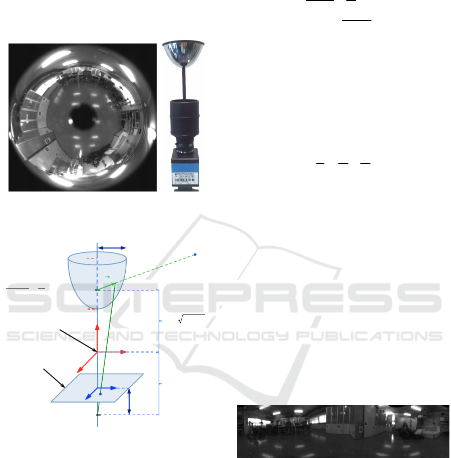
to the image plane, p. (i, j) is the reference system of
the image plane and (x
c
, y
c
, z
c
) is the world reference
system. The figure shows some of the most relevant
parameters of the hyperbolic mirror and the camera.
(a) (b)
Figure 1: (a) Actual omnidirectional image. (b) Actual om-
nidirectional vision system.
z
c
F
F’
c
! ! !
!
! !
!
!
p
P
y
c
x
c
j
i
B
A
Origin
h
r
max
!!
Image plane
Mirror equation:
!
!
!
! !
!
!
!
!
!
!
!
!
!
!
! !!!
Figure 2: Catadioptric system used to capture the synthetic
omnidirectional images, using a hyperbolic mirror.
The basis of this system is mainly based on the
beam trajectory from the objects in the environment
to the camera focus (F). Firstly, the beam leaves from
the objects and it arrives to the hyperbolic mirror. Fi-
nally, the beam reflects on the mirror and goes to-
wards the camera focus (F), appearing on the image
plane.
The Equation 1 defines the hyperbolic mirror.
This mirror is symmetric and its dimensions are de-
fined by a and b. These variables also define the dis-
tance between the focus of the hyperbolic mirror and
the origin of the world coordinate system, c (Equation
2).
x
2
c
+ y
2
c
a
2
−
z
2
c
b
2
= −1 (1)
c =
p
a
2
+ b
2
(2)
The hyperbolic mirrors are widely used to cre-
ate omnidirectional images thanks to their properties
(Zivkovic and Booij, 2006). However, there are many
other kinds of vision systems that provide omnidi-
rectional images, such as parabolic mirrors, spherical
mirrors or conic mirrors (Nene and Nayar, 1998) and
even polar arrays of cameras (Perazzi et al., 2015).
Equation 3 defines the equation of parabolic mir-
rors and Equation 4 defines the equation of spherical
mirrors.
z
c
c
=
x
2
c
a
2
+
y
2
c
b
2
(3)
(x
c
− x
0
)
2
+ (y
c
− y
0
)
2
+ (z
c
− z
0
)
2
= r
2
(4)
where (x
0
, y
0
, z
0
) are the coordinates origin of the
sphere with respect to the reference system (x
c
, y
c
, z
c
);
a, b, c define the geometry of the parabolic mirror and
r is the sphere radius.
Starting from an omnidirectional image it is pos-
sible to obtain a panoramic version using a simple
program to transform the polar coordinates of the
omnidirectional image into the cartesian coordinates
of the panoramic image. The Figure 3 shows the
panoramic image obtained from the omnidirectional
image showed in Figure 1(a). The platform is also
very useful to obtain other different projections such
as orthographic views, cylindrical and unit sphere
projections. Some mapping and localization algo-
rithms make use of such information (Amor´os et al.,
2014).
Figure 3: Panoramic image obtained from the omnidirec-
tional image of Figure 1(a).
3 SIMULATION ALGORITHM
In this work, the vision systems are modeled by an
algorithm with the purpose of creating images from
a virtual environment. This program is based on the
beams trajectory and the intersections between planes
and straight lines.
To generate an image, it is necessary first to cre-
ate a virtual environment. This environment has to
ICINCO 2016 - 13th International Conference on Informatics in Control, Automation and Robotics
354
be defined in such a way that the intersection between
the beams and the objects within this environment can
be simulated efficiently. We have defined these ob-
jects as clusters of faces and each of these faces is
contained in a different plane. As an example, six
faces in six different planes define a cube. From this
standpoint, the virtual environment is formed by a set
of faces in the space defining objects with different
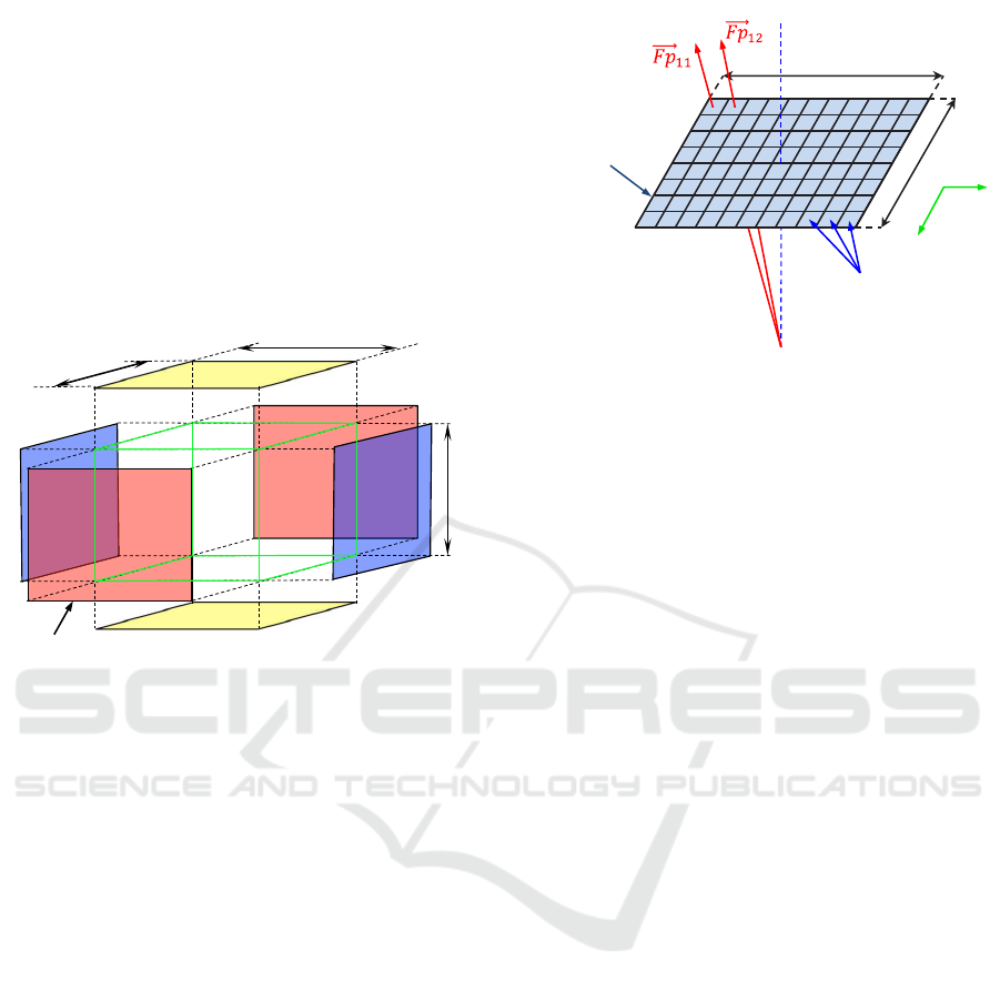
shapes. The Figure 4 shows the elements that form
a parallelepiped using these faces; the parallelepiped
is defined by l
1
, l
2
, l
3
, its position in the environment
and the color of each face.
l
2
l
3
l
1
faces
Figure 4: Faces of an object in a virtual environment.
Once all the objects have been generated, the al-
gorithm creates the images by calculating each beam
trajectory in the system.
Considering that the most complex vision system
is the catadioptric system, the algorithm is explained
using the omnidirectional vision as a basis for the ex-
planation. The other systems have been simulated us-
ing the same concepts.
Firstly, the image plane is defined choosing the
resolution of the omnidirectional image (k
x
x k
y
) and
the distance h in Figure 2 (distance between the image
plane and the focus of the camera).
Secondly, the vector
−→
Fp
ij
is calculated from the
focus of the camera F to each pixel in the image(i, j)
per each pixel of the image plane (Equation 5). p
ij
is the pixel selected to trace the beam. The Figure
5 shows the image plane and the beam trajectory per
each pixel p
ij
.
−→
Fp
ij
=
−→
p
ij
−
−→
F (5)
where
−→
p
ij
and
−→
F are the vectors whose components
are the coordinates of p
ij
and F respectively, with re-
spect to the world reference system {x
c
, y
c
, z
c
}.
Thirdly, the straight line r1
ij
defined by the vector
−→
Fp
ij
and the point F (as a point of this line) is used to
calculate the intersection point (Q
ij
) between r1
ij
and
the hyperbolic mirror (Equation 1).
k
x
k
y
F
Image plane
Pixels
Beam trajectory
i
j
Figure 5: Beam trajectories for each pixel in the image
plane.
Fourthly, this point (Q
ij
) is used to calculate the
vector
−→
P
ij
by means of this equation:
−→
P
ij
=
−→
Q
ij
−
−→
F
′
(6)
where
−→
Q
ij
and
−→
F
′
are the vectors whose components
are the coordinates of Q
ij
and F
′
respectively, with
respect to the reference system {x
c
, y
c
, z
c
}. F
′
is the
focus of the hyperbolic mirror (Figure 2).
Finally, the straight line r2
ij
defined by the vector
−→
P
ij
and the point F
′
is used to calculate the inter-
section point (P) between them and any object in the
environment. When r2
ij
intersects with a face of an
object, the pixel of the image plane used in Equation
5 takes the color value of that face of the object. r2
ij
may intersect with several faces, but only the first in-
tersection is considered (this is what happens in a real
situation).
Therefore, this process creates a cluster of vectors
composed of all of the vectors
−→
P
ij
, one per each pixel
of the plane image, and a point (F
′
). The intersections
with the objects in the environment are calculated us-
ing the lines defined by these vectors and the point
(F
′
).
To simulate the translation of the robot it is only
necessary translate the point (F
′
). The cluster of vec-
tors is not modified. The change in robot elevation is
simulated using a translation in the z axis. The fol-
lowing equation shows the translation of the point F
′
:
−→
F
′
T
=
−→
F
′
+
−→
T (7)
where
−→
F
′
T
is the vector whose components are the
coordinates of F
′
T
, with respect to the reference sys-
tem {x
c
, y
c
, z
c
}. F
′
T
is the point F
′
translated and T is
the translation vector.
Generation of Data Sets Simulating Different Kinds of Cameras in Virtual Environments
355
At last, to take into consideration that the robot
may have different orientations in the space, it is nec-
essary to use one or more rotation matrices to trans-
form each vector
−→
P :
R
x
(θ
x
) =
1 0 0
0 cosθ
x
−sinθ
x
0 sinθ
x
cosθ
x
(8)
R
y
(θ
y
) =
cosθ
y
0 sinθ
y
0 1 0
−sinθ
y
0 cosθ
y
(9)
R
z
(θ
z
) =
cosθ
z
−sinθ
z
0
sinθ
z
cosθ
z
0
0 0 1
(10)
R
total
= R
x
(θ
x
) ·R
y
(θ
y
) ·R
z
(θ
z
) (11)
−→
PR
i
= R
total
·
−→
P
i
(12)
where R
x
, R
y
and R
z
are the rotation matrix with re-
spect to each axis, R
total
is the resulting rotation ma-
trix and
−→
PR is the vector
−→
P rotated.
The scheme of the generation process of the om-
nidirectional images is defined in Code 1.
Code 1: Simulation pseudocode.
1 f or i =1:1: px
3 fo r j =1:1: py
5 Choose the point p ( i , j ) from th e
image plane
7 Ca lc ul at ion of v Fp ( i , j ) =p ( i , j )−F
9 r1 i s de f ined by v Fp and F
11 pi ( i , j ) = i n t e r se ct io n between r1 and
the hy perbo l i c m irror
13 Cal cu l a t i o n of v P ( i , j )=Q( i , j )−F ’
15 r2 i s de f ined by v P and F ’
17 P= f i r s t i nt e r se ct io n po i nt between
the l i n e r2 and an o b je ct in the
v i rt u a l environment
19 image ( i , j ) = color of th e o b j e ct in the
point P
21 end
23 end
4 ADDITIONAL IMAGE
CAPTURE OPTIONS AND
DESCRIPTION
The main objective of this work is to present a plat-
form to create images from a virtual environment as
presented in the previous section. Besides this func-
tion, the platform can carry out another advanced
tasks using the foundations presented in Section 3.
Since this platform has been designed to test lo-
calization and mapping algorithms we include some
of the most used image description methods. We have
included both local landmark extraction methods and
global appearance methods.
On the one hand, the platform permits extracting
and describing both the SIFT (Scale-Invariant Fea-
ture Transform) (Lowe, 1999) or SURF (Speeded-
Up Robust Features) (Bay et al., 2006) features from
each virtual omnidirectional image to carry out exper-
iments using this kind of descriptors. All the parame-
ters are tunable.
On the other hand, several global appearance de-
scriptors can also be calculated using the platform.
Some examples are the Radon transform (Radon,
1917; Berenguer et al., 2015), the Fourier Signature
(FS), Principal Components Analysis (PCA), His-
togram of Oriented Gradients (HOG) and gist de-
scriptor. Many of these descriptors are used in the
work of (Pay´a et al., 2014). And also, the user can
configure all the parameters.
The creation of each environment is very easy
through command lines. It is possible to create any
new object defining its shape, position, orientation
and size. The virtual environments can be defined in-
doors or outdoors.
This is very useful to test the localization algo-
rithms under realistic conditions. Usually, the map
images are captured on a specific time of day but the
localization must be carried out in different moments.
It implies different lighting conditions and also other
changes in visual information, such as occlusions in
scenes due to the presence of persons or other mobile
objects around the robot.
Taking these facts into account, the platform has
also other configurable options to generate the im-
ages such as adding light points, noise and occlusions
(adding objects in the virtual environment). It is also
possible to change the color of each object in the vir-
tual environment.
The omnidirectional images can also be trans-
formed in different projections (such as orthographic
views, cylindrical and unit sphere projections) using
the platform presented. It is an interesting character-
istic because there are many works that use panoramic
ICINCO 2016 - 13th International Conference on Informatics in Control, Automation and Robotics
356
images and other projections in localization tasks
(Pay´a et al., 2014).
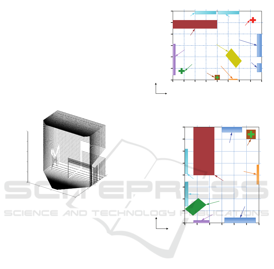
At last, nowadays, some researches make use of
point cloud data in localization tasks, such as (An-
dreasson and Lilienthal, 2010). An additional option
has been added to the platform to generate the point
cloud data of the virtual environment. This process
consists in saving all P points (intersection point be-
tween each line r
2
and the objects in the virtual envi-
ronment). This point cloud data saves the coordinates
x, y and z of each point P and the color of the object
in this point and emulates the information captured by
an RGB-d camera. The Figure 6 shows a point cloud
data of a sample virtual environment captured using a
simple virtual camera.
0
1000
2000
3000
−4000
−2000
0
2000
4000
0
500
1000
1500
2000
2500
Figure 6: Point cloud data of a sample virtual environment.
The presented platform uses a simple user inter-
face which uses an object library to create the virtual
environment. Also, this interface permits creating a
path to generate images along it.
5 EXPERIMENTS
In order to check the performance of the proposed
method, we have created two virtual environments
which represent two different rooms. In these envi-
ronments it is possible to create an image using dif-
ferent types of vision systems from any position and
orientation. The Figure 7 shows a bird eye’s view of
both environments.
Different sample images have been taken using
several kinds of visual systems. The figure 8 shows
three different kinds of images taken using a single
camera, a panoramic camera and a stereo camera.
The resolution of the images can be configured
freely. To generate omnidirectional images, we have
chosen 250x250 pixels to carry out the experiments.
The parameters used in the mirror equation (Equation
!"
#!!!"
$!!!"
%!!!"
&%!!!"
&$!!!"
&#!!!"
%!!!" '!!!"$!!!"#!!!"!"&#!!!"&$!!!"&%!!!"&'!!!"
()*+,-""
./01,"
2345)6"#"
2345)6"$"
2,3-5"708,9+"$"
2,3-5"708,9+"#"
:1)*,+"#"
:1)*,+"$"
:/-;,+"
<))-"
=1)6,-;)+"
>"
?"
!"#$%&"'(")*+*
(a)
!"&A!!"&#!!!"&#A!!"
#A!!"
#!!!"
A!!"
#A!!"
$!!!"
#!!!"
A!!"
!"
&A!!"
&#!!!"
&#A!!"
&$!!!"
()*+,-""
./01,"
2345)6"#"
2345)6"$"
;1)*,+"#"
;1)*,+"$"
;/-<,+"
=))-"
>1)6,-<)+"
?"
@"
!"#$%&"'(")*,*
(b)
Figure 7: (a) Bird eye’s view of the environment 1. (b) Bird
eye’s view of the environment 2. (Dimensions in millime-
ters).
1) can also be configured, in this experiment we have
chosen a = 40 and b = 160.
Several sets of images have been captured in each
environment, considering changes in robot elevation,
translation, rotation and inclination before capturing
each new image. The figure 9 shows the coordinates
of the mirror focus F
′
, the rotation in each axis, and
the generated images.
As mentioned previously in Section 4, the plat-
form can also transform these omnidirectional images
in orthographicviews, cylindrical and unit sphere pro-
jections. The Figure 10 shows an example of the
panoramic transformation of an omnidirectional im-
age from the environment 1.
Generation of Data Sets Simulating Different Kinds of Cameras in Virtual Environments
357

Figure 8: Different kinds of visual systems. Top left, sin-
gle camera. Top right, panoramic camera. Bottom, stereo
camera.
6 CONCLUSIONS
In this work a platform to create different kinds of im-
ages using virtual environments has been presented.
This method is mainly based on the beams trajec-
tory and the intersections between planes and straight
lines. Furthermore, it can create images from any po-
sition of the environment and with any robot orienta-
tion.
The platform can also extract SIFT and SURF fea-
tures of each image, create global appearance descrip-
tors (Radon, FS, PCA and HOG), add changes in the
environment (light points, noise, occlusions and col-
ors). Also it is possible to generate images using dif-
ferent kinds of visual sensors such as single cameras,
panoramic cameras, stereo cameras and catadioptric
systems, and, at last, the platform can save the point
cloud data of the environment.
The experiments included in this paper generate
our own image database created synthetically from
two different environments. The results demonstrate
that the method is able to create sets of omnidirec-
tional images with flexibility and efficiency.
We expect this platform constitutes an alternative
to generate easy, quickly and with flexibility image
sets to test and tune any new visual mapping and lo-
calization algorithm. This may help to accelerate the
initial stages of the algorithm design and to find more
quickly the optimal value for the parameters of the
visual system, images and the descriptors.
The results of this work encourage us to continue
this research line. It will be interesting to improvethis
platform to add more types of changes in the environ-
ment such as shadows. Also, this method will permit
!"#$%&"'(")*+*
!"#$%&"'(")*,*
!
!
!!!!! !
!
!
! !!!
!
!
! !"!
!!!
!
! !"!!!
!
!
! !!!
!
!
! !"!
!!!
!
! !"!!!
!
!
! !!!
!
!
! !"!
!!!
!
! !"!!!
!
!
!!!!!" !
!
!
!"#!!!!" !
!!!
!
! !"!!!!
!
!
! !"!!
!!!
!
! !"!!!!
!
!
! !"!
!
!
! !!!
!
!
! !!!
!
!
!"#!!!!" !
!
!
!"#!!!!" !
-(.*
-(.*
-(.*
-(.*
-(.*
-(.*
-(.*
-(.*
-(.*
-(.*
-(.*
-(.*
-(.*
-(.*
-(.*
Figure 9: Virtualimages generated with the platform in both
environments. Some changes in robot position and orienta-
tion have been simulated to obtain these images. (Dimen-
sions in centimeters).
designing some algorithms to localize the robot us-
ing differentkinds of environments, and incorporating
these algorithms as additional options of the platform.
ACKNOWLEDGEMENTS
This work has been supported by the Spanish govern-
ment through the project DPI2013-41557-P: “Nave-
gaci´on de Robots en Entornos Din´amicos Mediante
Mapas Compactos con Informaci´on Visual de Apari-
encia Global” and by the Generalitat Valenciana
(GVa) through the project GV/2015/031: “Creaci´on
de mapas topol´ogicos a partir de la apariencia global
de un conjunto de escenas.”
ICINCO 2016 - 13th International Conference on Informatics in Control, Automation and Robotics
358
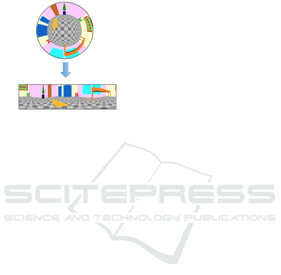
Figure 10: Sample virtual panoramic image obtained from
a virtual omnidirectional image in environment 1.
REFERENCES
Amor´os, F., Pay´a, L., Reinoso, O., and Valiente, D. (2014).
Towards relative altitude estimation in topological
navigation tasks using the global appearance of vi-
sual information. In VISAPP 2014, International Con-
ference on Computer Vision Theory and Applications,
volume 1, pages 194–201.
Andreasson, H. and Lilienthal, A. (2010). 6d scan regis-
tration using depth-interpolated local image features.
Robotics and Autonomous Systems, 58(2).
Bay, H., Tuytelaars, T., and Gool, L. (2006). Surf:
Speeded up robust features. Computer Vision at
ECCV, 3951:404–417.
Berenguer, Y., Pay´a, L., Ballesta, M., and Reinoso, O.
(2015). Position estimation and local mapping us-
ing omnidirectional images and global appearance de-
scriptors. Sensors, 15(10):26368.
Burbridge, C., Spacek, L., and Park, W. (2006). Omnidirec-
tional vision simulation and robot localisation. Pro-
ceedings of TAROS, 2006:32–39.
Lowe, D. (1999). Object recognition from local scale-
invariant features. In ICCV 1999, International Con-
ference on Computer Vision, volume 2, pages 1150–
1157.
Maohai, L., Han, W., Lining, S., and Zesu, C. (2013). Ro-
bust omnidirectional mobile robot topological naviga-
tion system using omnidirectional vision. Engineer-
ing Applications of Artificial Intelligence, 26(8):1942
– 1952.
Mondragon, I., Olivares-M´ended, M., Campoy, P.,
Mart´ınez, C., and Mejias, L. (2010). Unmanned aerial
vehicles uavs attitude, height, motion estimation and
control using visual systems. Autonomous Robots,
29:17–34.
Nene, S. and Nayar, S. (1998). Stereo with mirrors. In Pro-
ceedings of the 6th Internation Conference on Com-
puter Vision, Bombay, India.
Pay´a, L., Amor´os, F., Fern´andez, L., and Reinoso, O.
(2014). Performance of global-appearance descrip-
tors in map building and localization using omnidi-
rectional vision. Sensors, 14(2):3033–3064.
Pay´a, L., Fern´andez, L., Gil, L., and Reinoso, O. (2010).
Map building and monte carlo localization using
global appearance of omnidirectional images. Sen-
sors, 10(12):11468–11497.
Peasley, B. and Birchfield, S. (2015). Rgbd point cloud
alignment using lucas-kanade data association and au-
tomatic error metric selection. IEEE Transactions on
Robotics, 31(6):1548–1554.
Perazzi, F., Sorkine-Hornung, A., Zimmer, H., Kaufmann,
P., Wang, O., Watson, S., and Gross, M. (2015).
Panoramic video from unstructured camera arrays.
Computer Graphics Forum, 34(2):57–68.
Radon, J. (1917). Uber die bestimmung von funktio-
nen durch ihre integralwerte langs gewisser mannig-
faltigkeiten. Berichte Sachsische Akademie der Wis-
senschaften, 69(1):262–277.
Valiente, D., Gil, A., Fern´andez, L., and Reinoso, O. (2014).
A comparison of ekf and sgd applied to a view-based
slam approach with omnidirectional images. Robotics
and Autonomous Systems, 62(2):108 – 119.
Wang, X., Tang, J., Niu, J., and Zhao, X. (2016). Vision-
based two-step brake detection method for vehicle
collision avoidance. Neurocomputing, 173, Part 2:450
– 461.
Winters, N., Gaspar, J., Lacey, G., and Santos-Victor, J.
(2000). Omni-directional vision for robot navigation.
IEEE Workshop on Omnidirectional Vision, pages 21–
28.
Wu, J., Zhang, H., and Guan, Y. (2014). An efficient visual
loop closure detection method in a map of 20 million
key locations. In 2014 IEEE International Conference
on Robotics and Automation (ICRA), pages 861–866.
Zivkovic, Z. and Booij, O. (2006). How did we built our hy-
perbolic mirror omni-directional camera practical is-
sues and basic geometry. Intelligent Systems Labora-
tory Amsterdam, University of Amsterdam, IAS tech-
nical report IAS-UVA-05-04.
Generation of Data Sets Simulating Different Kinds of Cameras in Virtual Environments
359
