
Image Super Resolution from Alignment Errors
of Image Sensors and Spatial Light Modulators
Masaki Hashimoto, Fumihiko Sakaue and Jun Sato
Department of Computer Science and Engineering, Nagoya Institute of Technology, Gokiso, Showa,
466-8555, Nagoya, Japan
hashimoto@cv.nitech.ac.jp, {sakaue, junsato}@nitech.ac.jp
Keywords:
Image Super Resolution, Alignment Error, LCoS Device.
Abstract:
In this paper, we propose a novel method for obtaining super resolution images by using alignment errors
between an image sensor and a spatial light modulator, such as LCoS device, in the coded imaging systems.
Recently, coded imaging systems are often used for obtaining high dynamic range (HDR) images and for de-
blurring depth and motion blurs. For obtaining accurate HDR images and unblur images, it is very important
to setup the spatial light modulators with cameras accurately, so that the one-to-one correspondences hold be-
tween light modulator pixels and camera image pixels. However, the accurate alignment of the light modulator
and the image sensor is very difficult in reality. In this paper, we do not adjust light modulators and image
sensors accurately. Instead, we use the alignment errors between the light modulators and the image sensors
for obtaining high resolution images from low resolution observations in the image sensors.
1 INTRODUCTION
Obtaining high resolution images is very important
for high quality visualization and for accurate 3D re-
construction. For obtaining high resolution images,
sensing devices has been improved in recent yeas, and
the number of pixels in image sensors becomes larger
and larger. However, the image sensors with large
pixel size are very expensive, and are not easy to use.
For obtaining high resolution images without us-
ing large image sensors, image super resolution meth-
ods have been developed for many years (Tsai and
Huang, 1984; Baker and Kanade, 2002; Capel and
Zisserman, 2001; Glasner et al., 2009; Huang et al.,
2015; Dong et al., 2014). These methods enable us
to obtain high resolution images from low resolution
image sensors, and thus they are very useful in many
applications.
The image super resolution methods can be di-
vided into two classes. The first class of methods is
to generate a high resolution image from just a sin-
gle low resolution image (Glasner et al., 2009; Huang
et al., 2015; Dong et al., 2014). The prior knowl-
edge has often been used for generating a plausible
high resolution image from a single low resolution
image. However, since these methods are based on
the prior knowledge, if the prior does not fit the sit-
uation, the estimated high resolution images may be-
come very different from the ground truth high reso-
lution images. The second class of methods is based
on the multiple observation from low resolution sen-
sors (Tsai and Huang, 1984; Schultz and Stevenson,
1996; Baker and Kanade, 2002; Capel and Zisserman,
2001). In these methods, multiple sensors or single
moving sensor are used for obtaining independent low
resolution images, and these images are combined for
recovering high resolution images. Since these meth-
ods are based on the real observations, they can gen-
erate physically correct high resolution images. How-
ever, these methods require a set of multiple sensors
or a single moving sensor for obtaining multiple ob-
servations.
In this method, we propose a method for gen-
erating high resolution images from a single static
image sensor, without using any prior. For obtain-
ing physically correct high resolution images from a
static image sensor, we use a spatial light modulator,
such as LCoS device, with an image sensor. Recently,
coded imaging has been studied extensively, and spa-
tial light modulators, such as LCoS device, have been
used with image sensors for obtaining coded images.
The coded imaging has been used for generating high
dynamic range images from low dynamic range sen-
sors (Mannami et al., 2007; Uda et al., 2016), and for
obtaining 4D light fields and debulrring images (Na-
gahara et al., 2010). In these methods, it is very
288
Hashimoto M., Sakaue F. and Sato J.
Image Super Resolution from Alignment Errors of Image Sensors and Spatial Light Modulators.
DOI: 10.5220/0006265702880293
In Proceedings of the 12th International Joint Conference on Computer Vision, Imaging and Computer Graphics Theory and Applications (VISIGRAPP 2017), pages 288-293
ISBN: 978-989-758-225-7
Copyright
c
2017 by SCITEPRESS – Science and Technology Publications, Lda. All rights reserved
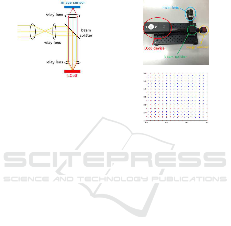
Figure 1: Coded imaging system, which consists of an
LCoS device and an image sensor.
important to setup the spatial light modulators with
cameras accurately, so that the one-to-one correspon-
dence between light modulator pixels and camera im-
age pixels hold. However, the accurate alignment of
the light modulator and the image sensor is very dif-
ficult in reality. In this paper, we do not adjust the
light modulators and Image sensors. Instead, we use
the alignment errors between the light modulators and
the image sensors for obtaining high resolution im-
ages from low resolution observations in the image
sensors.
2 CODED IMAGING SYSTEM
In general, coded imaging systems combine pixel-
wise light modulators, such as LCoS and LCD, with
image sensors, so that the input light at each pixel of
the image sensor can be controlled. Fig.1 shows an
example setup of the coded imaging systems using
LCoS device. As shown in this figure, the input light
first goes to the LCoS device, and is reflected at the
LCoS. Then, the reflected light goes into the image
sensor, and is observed. The reflectance of LCoS can
be controled pixel by pixel, and thus the input light at
the image sensor can be controlled pixel by pixel.
In these systems, it is very important to obtain
one-to-one correspondence between image pixels on
the image sensor and image pixels on LCoS device.
Since the pixel size of the image sensor and LCoS de-
vice are different in general, we often use affine trans-
formation or homography to obtain pixel-wise corre-
spondence between them.
However, it is actually impossible to obtain exact
one-to-one correspondence between the image sensor
and LCoS device, since there exist sub-pixel align-
ment errors between the image pixels of image sensor
and the image pixels of LCoS device. Thus, the in-
(a)
(b)
Figure 2: Real coded imaging system and its alignment er-
rors. (a) shows an example of coded imaging system. (b)
shows magnified alignment errors between the pixels of im-
age sensor (blue) and the pixels of LCoS device (red).
put light at each pixel of the image sensor cannot be
controlled perfectly in actual systems. Fig. 2 shows
an example of real coded imaging systems, and its
alignment error of image sensor and LCoS device. As
shown in this figure, there exist sub-pixel alignment
errors between the image pixels of image sensor and
the image pixels of LCoS device.
Although these alignment errors of image pixels
are problematic in the sense of point correspondences,
it is very good in the sense of image measurement,
since these alignment errors enable us to obtain more
detail information about the input light distribution.
In the following sections, we describe a method for
obtaining super resolution images by using the align-
ment errors between image sensors and LCoS de-
vices. Although we explain our method based on
LCoS devices in this paper, our method is not limited
to LCoS devices, and it can be applied to any spatial
light modulator used in the coded imaging systems.
3 IMAGE OBSERVATION IN
CODED IMAGING SYSTEM
We first consider an image observation model of a
coded imaging system.
Suppose we have a high resolution image X.
Image Super Resolution from Alignment Errors of Image Sensors and Spatial Light Modulators
289

When we observe X by a low resolution image sen-
sor, the observed image Y can be described by using
the high resolution image X as follows:
Y = DX (1)
where, D denotes a degradation matrix, which rep-
resents the degradation of resolution caused by the
low resolution image sensor. The matrix D represent
not only the change in resolution, but also image blur
caused by imaging.
Now, suppose we obtain N observations by a
coded imaging system changing the coded pattern
on the LCoS device. Then, the observed image Y
i
(i = 1, · ·· , N) can be described as follows:
Y
i
= D
i
X (2)
where D
i
denotes the ith degradation matrix generated
by the ith coded pattern C
i
displayed on the LCoS de-
vice, and thus it can be described as follows:
D
i
= C
i
D (3)
In this case, the rank of [D
⊤
1
, ··· , D
⊤
N
]
⊤
is same as
the rank of D, and thus the observed images Y
i
(i =
1, · ·· , N) are dependent on each other. As a result, we
cannot recover the original high resolution image X
from low resolution coded images Y
i
(i = 1, ·· · , N).
Thus, the image super resolution cannot be achieved
by the standard coded imaging.
4 IMAGE SUPER RESOLUTION
FROM ALIGNMENT ERRORS
We next consider the alignment error between image
sensors and LCoS devices. As we described above,
the sub-pixel alignment errors between image sensors
and LCoS devices is inevitable in real systems. Un-
like the existing works, we use these sub-pixel align-
ment errors positively for obtaining high resolution
images from low resolution observations.
Suppose we have alignment errors between an im-
age sensor and an LCoS device as shown in Fig. 3 (a).
If we open all the pixels of LCoS device, we observe
all the input light. Now, if we open odd rows of LCoS
device and close even rows of it, then each pixel of the
image sensor observes input light as shown in Fig. 3
(b). We next close odd rowsand open even rows of the
LCoS device. Then, the observed light at each pixel
of the image sensor is as shown in Fig. 3 (c). From
Fig. 3 (b) and (c), we find that the observed light is
different from each other and we can obtain indepen-
dent information on the high resolution input light by
controlling the LCoS device.
(a)
(b) (c)
Figure 3: Coded imaging under the existence of alignment
errors. The black lines and the red lines in (a) show im-
age pixels of image sensor and LCoS device respectively.
(b) shows image observation under an LCoS device control,
in which odd rows are open and even rows are closed. (c)
shows image observation under another LCoS device con-
trol, in which odd rows are closed and even rows are open.
We next consider the degradation matrix D
i
of ob-
servation under the ith coded pattern of LCoS device
assuming that the alignment errors exist. If we con-
sider the sub-pixel alignment errors, the degradation
matrix D
i
is described as follows:
D
i
= DA
i
(4)
where, A
i
is a matrix which represents the sub-pixel
alignment errors and the ith coded pattern of LCoS
device. Unlike the degradation matrix in Eq.(3), we
can obtain independent D
i
in Eq.(4) by changing the
coded pattern of LCoS device. Thus, we can obtain
independent information on the high resolution im-
age X from the multiple low resolution observations
Y
i
(i = 1, ··· , N) obtained from N different coded pat-
terns of LCoS device. As a result, the image super
resolution can be achieved from Y
i
(i = 1, ·· · , N) by
considering the alignment errors between the image
sensor and LCoS device.
The image super resolution can be formalized as a
cost minimization problem as follows:
X = argmin
X
N
∑
i=1
||Y
i
− D
i
X||
2
+ α|∇X|
1
(5)
where, the first term in the cost function is a data term,
and the second term is a regularization term. ∇ de-
notes the Laplacian, and | · |
1
denotes the L
1
-norm. α
shows a weight for the regularization term.
VISAPP 2017 - International Conference on Computer Vision Theory and Applications
290

By estimating high resolution images X from
Eq.(5), we can achieve image super resolution using
alignment errors of image sensors and LCoS devices.
5 ESTIMATION OF
DEGRADATION MATRIX
In this method, the estimation of the degradation ma-
trix D
i
is very important. It seems that if the pixel
sizes of the image sensor and the LCoS device are
known, we can estimate the degradationmatrix. How-
ever, this is not the case in the real system, since the
degradation matrix depends not only on the geomet-
ric relationship between the image sensor and LCoS
device, but also on the various photometric properties
of LCoS and image sensor. Thus, in our method, we
estimate the degradation matrix D
i
by using real ob-
servations.
Let us consider the case, where we estimate the ith
degradation matrix D
i
. We first prepare M different
high resolution images, X
j
( j = 1, · ·· , M), and ob-
serve these high resolution images by using the coded
imaging system. Then, we obtain M low resolution
images, Y
j
i
( j = 1, ··· , M). Then, these image obser-
vations can be described as follows:
Y
j
i
= D
i
X
j
(6)
Thus, we estimate D
i
, from X
j
and Y
j
i
, so that
Eq.(6) holds. This is achieved by estimating D
i
by
solving the following minimization problem:
D
i
= argmin
D
i
M
∑
j=1
||Y
j
i
− D
i
X
j
||
2
+ β|D
i
|
1
(7)
where, β denotes a weight for the regularization term.
By estimating all the N degradation matrices D
i
(i =
1, · ·· , N) from Eq.(7), we obtain N degradation ma-
trices under N coded patterns shown to the LCoS de-
vices.
This method enables us to estimate precise degra-
dation matrices, which represent not only the geomet-
ric alignment errors between the image sensor and
the LCoS device, but also the photometric distortions
caused by the coded imaging system.
By using the deriveddegradation matrices, we can
achieve image super resolution by using the method
described in section 4.
6 EXPERIMENTS
In this section, we show the efficiency of the pro-
posed method by using the real coded imaging sys-
tem shown in Fig. 2 (a). As shown in Fig. 1, the light
Figure 4: Examples of high resolution images used for esti-
mating degradation matrices.
comes into the main lens is reflected at the beam split-
ter and goes to the LCoS device. Then the light is re-
flected by the LCoS device and goes to the image sen-
sor. The reflection at the LCoS can be controlled per
pixel. However, there exist alignment errors between
the image sensor and the LCoS as shown in Fig. 2 (b).
6.1 Estimation of Degradation Matrix
We first estimated the degradation matrices of this
coded imaging system. For this objective, we showed
480 high resolution images to the coded imaging sys-
tem, and low resolution images were obtained by the
system. Fig. 4 shows some example high resolution
images. These images were observed by the low res-
olution image sensor in the coded imaging system un-
der 100 different coded patterns shown on the LCoS
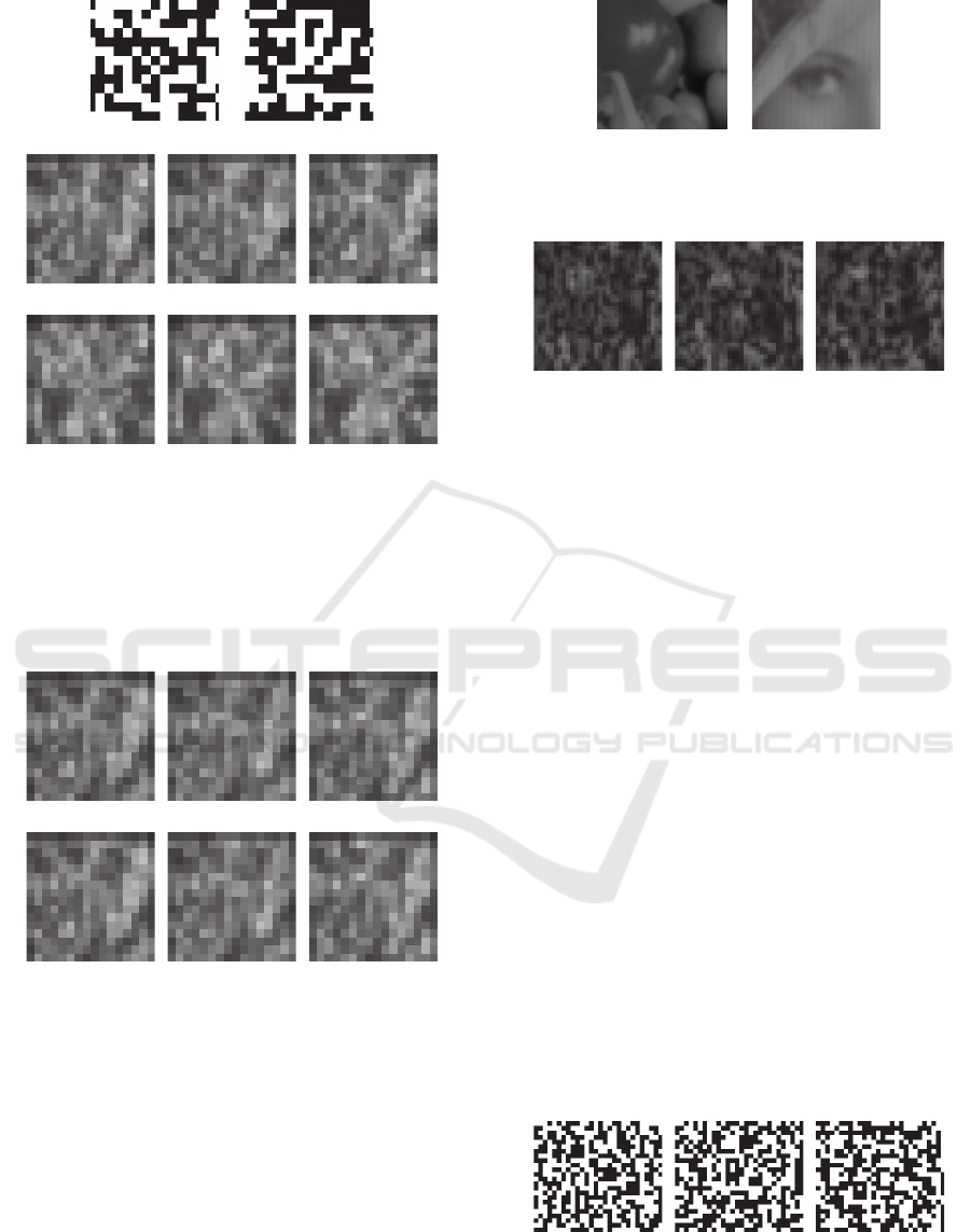
device. Fig. 5 shows two example coded patterns of
the LCoS device, and low resolution images observed
by the image sensor under these coded patterns. As
shown in Fig. 5, we in this experiment used random
patterns for coded patterns of the LCoS devise. This
is because, we do not know the amount of the align-
ment errors in the coded imaging system, and specific
systematic patterns may cause systematic errors. The
degradation matrices under these 100 coded patterns
were computed from these images by a method de-
scribed in section 5. We used β = 1.0 in this experi-
ment.
For verifying the accuracy of the estimated degra-
dation matrices, we generated 480 low resolution im-
ages from a high resolution image by using the esti-
mated degradation matrices, and compared them with
real low resolution images observed by the image sen-
sor changing the pattern of LCoS device. The PSNR
of the generated low resolution images was 40.35,
and thus we find that the degradation matrices were
estimated accurately. Fig. 6 shows some examples
of generated low resolution images and observed low
resolution images.
Image Super Resolution from Alignment Errors of Image Sensors and Spatial Light Modulators
291
(a) (b)
(a1) (a2) (a3)
(b1) (b2) (b3)
Figure 5: Two example coded patterns for LCoS device, and
observed images under these coded patterns. (a) and (b)
show two example coded patterns for LCoS device. (a1),
(a2) and (a3) show observed low resolution images under
the coded pattern (a). These three images are the observed
images of three high resolution images in Fig. 4. (b1), (b2)
and (b3) show those from the coded pattern (b).
generated images
observed images
Figure 6: Low resolution images generated from the degra-
dation matrices and low resolution images observed by the
image sensor under 3 different high resolution images.
6.2 Image Super Resolution from
Alignment Errors
We next show the results of image super resolution
from the alignment errors of image sensor and LCoS
device.
In this experiment, high resolution images shown
in Fig. 7 were observed by the low resolution image
sensor with LCoS device, and the observed images
(a) (b)
Figure 7: Original high resolution images used in our ex-
periments.
(a) (b) (c)
Figure 8: Example low resolution images observed by the
image sensor.
were used for recovering the original high resolution
images. 100 low resolution images were observed
changing the coded patterns shown on the LCoS de-
vice. The low resolution images are 32 × 32, and the
high resolution images are 64× 64.
Fig. 8 shows some examples of the observed low
resolution images. As shown in this figure, the low
resolution images are coded by using the LCoS de-
vice. The coded patterns of the LCoS device for these
images are shown in Fig. 9. From these 100 low res-
olution images, we estimated a high resolution image
by using the proposed method with α = 1.0. Fig. 10
shows the estimated high resolution images from the
proposed method as well as the high resolution im-
ages estimated from the standard bi-cubic method and
the original low resolution images. By comparing
Fig. 10 with Fig. 7, we find that the proposed method
can recover high resolution images much more accu-
rately than the bi-cubic method.
6.3 Accuracy Evaluation
We next evaluate the accuracy of the proposed method
by using synthetic image experiments. Since the ac-
(a) (b) (c)
Figure 9: Example coded patterns of the LCoS device.
These 3 coded patterns are corresponding to 3 observed im-
ages in Fig. 8.
VISAPP 2017 - International Conference on Computer Vision Theory and Applications
292
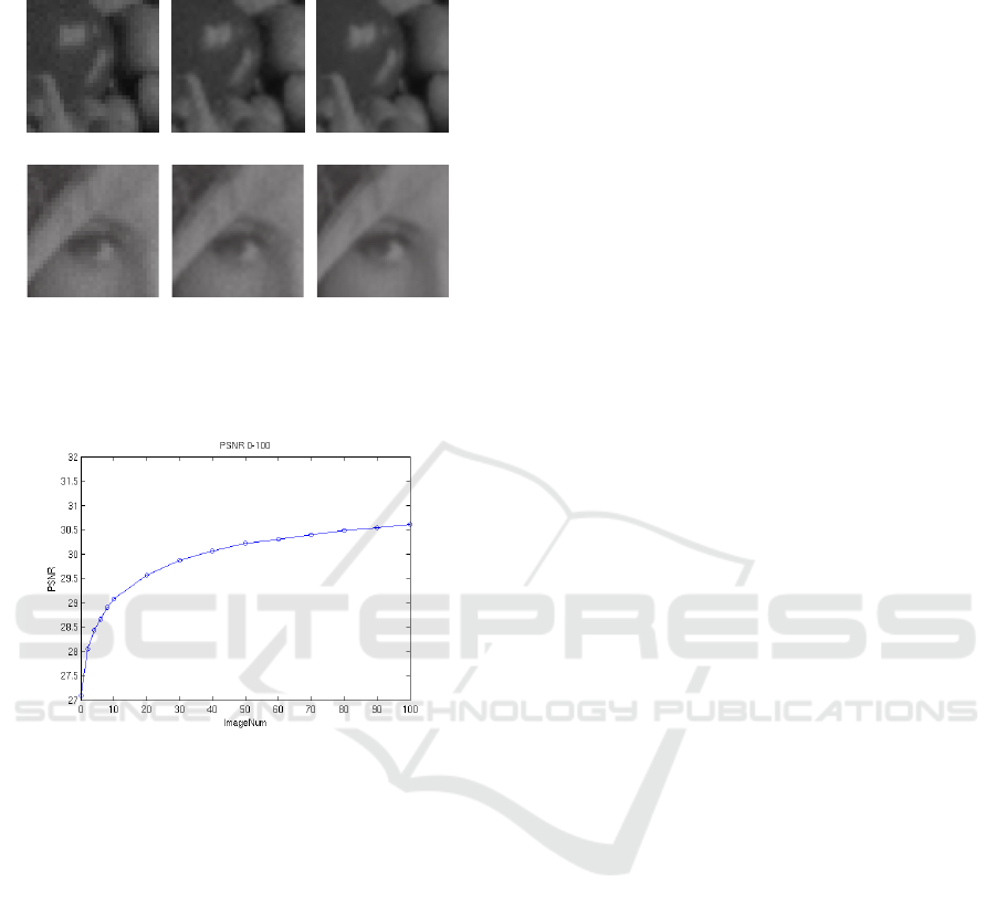
low resolution bi-cubic proposed
images method method
SSIM: 0.742 SSIM: 0.829 SSIM: 0.874
SSIM: 0.716 SSIM: 0.787 SSIM: 0.874
Figure 10: High resolution images estimated by using the
proposed method and the bi-cubic method as well as the
original low resolution images. SSIMs are also shown.
Figure 11: Relationship between the number of coded im-
ages and the accuracy of recovered high resolution images.
curacy of the proposed method depends on the num-
ber of low resolution images, we evaluated the rela-
tionship between the number of coded images and the
accuracy of high resolution images recovered from
the proposed method. The alignment error of LCoS
device and image sensor is simulated in the synthetic
images based on the real errors shown in Fig. 2.
Fig. 11 shows the changes in accuracy with re-
spect to the number of coded images. As shown in
this figure, the accuracy of the proposed method in-
creases as the number of coded images increases.
7 CONCLUSION
In this paper, we proposed a method for obtaining
high resolution images from low resolution observa-
tions by using alignment errors between an image
sensor and a spatial light modulator, such as LCoS de-
vice. In general, accurate alignment of the light mod-
ulator and the image sensor is very difficult in coded
imaging systems. In this paper, we showed that in-
dependent information on high resolution images can
be obtained from low resolution observations, if we
have alignment errors between the light modulators
and the image sensors. Based on this observation, we
proposed a method for obtaining high resolution im-
ages from low resolution observations in the image
sensors. The proposed method is tested by using a
real coded imaging system, and the efficiency of the
proposed method was shown from the experimental
results.
REFERENCES
Baker, S. and Kanade, T. (2002). Limits on super-resolution
and how to break them. IEEE Transactions on Pattern
Analysis and Machine Intelligence, 24(9):11671183.
Capel, D. and Zisserman, A. (2001). Super-resolution from
multiple views using learnt image models. In Proc.
CVPR, pages 627–634.
Dong, C., Loy, C., He, K., and Tang, X. (2014). Learn-
ing a deep convolutional network for image super-
resolution. In Proc. ECCV.
Glasner, D., Bagon, S., and Irani, M. (2009). Super-
resolution from a single image. In Proc. ICCV.
Huang, J., Singh, A., and Ahuja, N. (2015). Single image
super-resolution from transformed self-exemplars. In
Proc. CVPR, pages 5197–5206.
Mannami, H., Sagawa, R., Mukaigawa, Y., Echigo, T., and
Yagi, Y. (2007). High dynamic range camera using
reflective liquid crystal. In ICCV, pages 1–8.
Nagahara, H., Zhou, C., Watanabe, T., Ishiguro, H., and
Nayer, S. (2010). Programable aperture camera using
lcos. In ECCV, page 337350.
Schultz, R. and Stevenson, R. (1996). Extraction of high-
resolution frames from video sequences. IEEE Trans-
actions on Image Processing, 5(6):9961011.
Tsai, R. and Huang, T. (1984). Multiple frame image
restoration and registration. Advances in Computer
Vision and Image Processing, page 317339.
Uda, S., Sakaue, F., and Sato, J. (2016). Variable expo-
sure time imaging for obtaining unblurred hdr images.
IPSJ Transactions on Computer Vision and Applica-
tions, 8(3):17.
Image Super Resolution from Alignment Errors of Image Sensors and Spatial Light Modulators
293
