
Distributed Co-Simulation of Embedded Control Software with Exhaust
Gas Recirculation Water Handling System using INTO-CPS
Nicolai Pedersen
1,3
, Kenneth Lausdahl
2
, Enrique Vidal Sanchez
1
,
Peter Gorm Larsen
2
and Jan Madsen
3
1
MAN Diesel & Turbo, Teglholmsgade 41, 2450 Kbenhavn SV, Denmark
2
Department of Engineering, Aarhus University, Finlandsgade 22, Aarhus N, Denmark
3
Embedded Systems Engineering, Technical University of Denmark, Anker Engelunds Vej 1, Kgs. Lyngby, Denmark
Keywords:
INTO-CPS, Cyber-Physical-Systems, Co-Simulation, Parallel Simulation, Distributed Simulation, Embedded
Control System, Exhaust Gas Recirculation.
Abstract:
Engineering complex Cyber-Physical Systems, such as emission reduction control systems for large two-stroke
engines, require advanced modelling of both the cyber and physical aspects. Different tools are specialised for
each of these domains and a combination of tools validating different properties is often desirable. However, it
is non-trivial to be able to combine such different models of different constituent elements. In order to reduce
the need for expensive tests on the real system it is advantageous to be able to combine such heterogeneous
models in a joint co-simulation in order to reduce the overall costs of validation. This paper demonstrates how
this can be achieved for a commercial system developed by MAN Diesel & Turbo using a newly developed tool
chain based on the Functional Mock-up Interface standard for co-simulation supporting different operating
systems. The generality of the suggested approach also enables future scenarios incorporating constituent
models supplied by sub-suppliers while protecting their Intellectual Property.
1 INTRODUCTION
With increased complexity in physical dynamics, con-
trol and communication, the development of Cyber-
Physical Systems (CPS) require more advanced mod-
elling and specialized tools. For differential-equation
based continuous models, multiple tools are avail-
able (MathWorks, 2011; SYST
`
EMES, 2017; Kleijn,
2006), each with their specific specialization and va-
lidity. Discrete event models are often developed
within companies own software frameworks, or cre-
ated in one of the many tools available. The inter-
connection between the physical and cyber parts of
CPS is becoming more dependent and dynamical in-
fluences have to be considered. The main challenge
connecting these models comes from the fundamen-
tal differences in the underlying mathematical frame-
works, their simulation tools and how they are devel-
oped. In this regard one typically distinguishes be-
tween Discrete Event (DE) models based on discrete
mathematics and Continuous-Time (CT) models that
are based on differential equations. Many initiatives
for connection tools in a so called co-simulation have
been published (Fitzgerald et al., 2014; ITEA Office
Association, 2015). However, connecting the specific
tools making up the holistic simulation is often not the
only issue. Deviations in development platforms and
performance is as often the issue. A solution for this
is a distributed co-simulation, where models can be
executed, not only in the tool where they were devel-
oped, but also on the correct platform. Furthermore, a
distribution of the simulation makes it possible to in-
crease performance by utilizing additional hardware,
given that the models are prepared for it.
At MAN Diesel & Turbo (MDT) the conventional
approach for developing two-stroke combustion en-
gines with a distributed embedded control system is
being challenged. In particular for diesel engines pol-
lution is a key element that it is desirable to reduce
from a competitive perspective. New emission leg-
islation focuses on the reduction of especially NO
x
emission. Widely known emission reduction tech-
nologies for reducing NO
x
are selective catalytic re-
duction and Exhaust Gas Recirculation (EGR), both
being developed at MDT (MAN Diesel & Turbo,
2016). These systems require advanced algorithms
to control the complexity of the physical dynamics
of large engines. Historically, in the same way as
Pedersen, N., Lausdahl, K., Sanchez, E., Larsen, P. and Madsen, J.
Distributed Co-Simulation of Embedded Control Software with Exhaust Gas Recirculation Water Handling System using INTO-CPS.
DOI: 10.5220/0006412700730082
In Proceedings of the 7th International Conference on Simulation and Modeling Methodologies, Technologies and Applications (SIMULTECH 2017), pages 73-82
ISBN: 978-989-758-265-3
Copyright © 2017 by SCITEPRESS – Science and Technology Publications, Lda. All rights reserved
73
many other large organisations, MDT is divided into
different departments with different responsibilities.
In the control department at MDT, control algorithms
are created directly in the target software framework
with the possibility of performing Software In the
Loop (SIL) simulation during development. Models
of the physical behaviour are created in other depart-
ments of MDT using the tools most suitable for the
specific constituent system. For control system de-
velopment, the physical dynamics models are imple-
mented in an internally developed tool for CT simula-
tion called Dynamic Simulation Environment (DSE)
which is part of the software framework. The primary
focus in DSE is SIL/Hardware In the Loop (HIL),
and the physics models implemented here are often
an abstraction of high-fidelity models. Historically it
has been challenging inside MDT to enable heteroge-
neous collaborations between the different teams pro-
ducing models in different departments.
The software framework and DSE are based on
C++ and run on a 32-bit Linux platform while
the physical modelling tools often require Win-
dows. In this paper the current simulation process
at MDT is compared with an alternative using co-
simulation utilizing the Functional Mock-up Inter-
face (FMI) standard and the Co-simulation Orches-
tration Engine (COE) from the Integrated Tool Chain
for Model-based Design of Cyber-Physical Systems
(INTO-CPS) project. The aim with the approach sug-
gested in this paper is to reduce redundancy in the
development process and reuse models from differ-
ent departments. One of the main challenges is to
enable co-simulation across different hardware archi-
tectures and Operating System (OS) platforms due to
constraints from software frameworks, physical sim-
ulation tools and version compatibility.
In section 2 the overall system is presented. sec-
tion 3 describes the previous simulation of a specific
subsystem for EGR, and section 4 describes the ap-
proach taken to enable co-simulation. Afterwards,
section 5 describes the co-simulation results for the
EGR system. Finally, the paper concludes with sec-
tion 6.
2 EXHAUST GAS
RECIRCULATION WATER
HANDLING SYSTEM
The EGR system presented in this paper recirculates
exhaust gas to the intake manifold thereby reduc-
ing environmental impact while maintaining efficient
combustion. The unclean exhaust gas is potentially
Run/Running
WTS
RTU
EGR Unit
Water Mist
Catcher
Cooler
Buffer Tank
Circulation Pump
Receiving Tank
Pre-Spray
Exhaust Gas
EGR Blower
Mixing
Chamber
Cleaned Exhaust Air
Process Water
Sealing Valve
Receiving Tank
Level Valve
Spray Water
Sealing Valve
Supply Pump
Scavenge Air
Fresh Water
WTS Pump
WTU
Ocean
Drain
Tank
Sludge
Tank
Ambient Air
Externally Controlled
EGR Control Unit
Tank Level
Setpoint/Feedback
Run/Running
Setpoint/
Feedback
Setpoint/
Feedback
WTS Communication
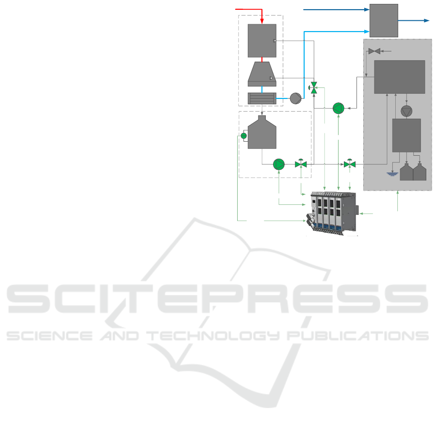
Figure 1: Water Handling System Setup.
damaging to the engine and has to be cleaned before
return, which is the purpose of the Water Handling
System (WHS). The system is shown in Figure 1
where the exhaust gas is drawn into the EGR Unit
using an EGR blower, it is then sprayed with water
and cooled so that a Water Mist Catcher (WMC) can
collect the damaging particles. Before the gas is re-
turned, the water is collected in the WMC and led to
a receiving tank. The water level in this tank is one of
the important variables that the WHS controls, as dis-
cussed in section 3.4. The water is pumped from the
receiving tank to an external constituent system (Wa-
ter Treatment System (WTS)) for processing where
the water is either cleaned and pumped back to the
EGR Unit, pumped overboard or stored for treatment
at a harbour.
At the chemical level, EGR is based on exchange
of the in-cylinder oxygen (O
2
) with carbon dioxide
(CO
2
) from the exhaust gas, which is re-circulated
into the scavenged air. The exchange of O
2
with CO
2
leads to a decrease of combustion speed, resulting
in lower peak temperatures during combustion. Fur-
thermore the exchange of O
2
with CO
2
results in a
higher in-cylinder heat capacity of the gas which also
lowers the combustion temperature. Lower combus-
tion temperatures and especially lower peak temper-
atures result in lower formation of thermal NO
x
dur-
ing the combustion process. The recirculated exhaust
gas is hotter and not as clean as the residual ambient
scavenge-air. To prevent Sulphur (SO
2
) and other par-
SIMULTECH 2017 - 7th International Conference on Simulation and Modeling Methodologies, Technologies and Applications
74

ticles from damaging the engine, cleaning and cool-
ing of the recirculated exhaust gas is required. A
WHS provides the water used for cleaning the ex-
haust gas in the EGR unit. To control the flow of
exhaust gas to the mixing chamber, an EGR blower
is installed. Water from the EGR unit is drained to
the Receiving Tank Unit (RTU) and recirculated to
the EGR unit. Part of the recirculated water is led
to the WTS to be cleaned and returned to the EGR
unit. The surplus of water originating from the com-
bustion process is drained from the WTS as bleed-
off water and discharged to the sea. The residuals
from the cleaning process are discharged to the sludge
tank. Depending on engine load and ambient condi-
tions the combustion process will accumulate water
in the system, which must be discharged as bleed-
off water. If discharged to the sea, the bleed-off wa-
ter must meet the quality criteria required by Interna-
tional Maritime Organization (IMO)
1
, presently de-
fined in the 2015 Guidelines for Exhaust Gas Clean-
ing Systems, MEPC 259 (68). Bleed-off water, which
does not meet the discharge criteria or cannot be dis-
charged to sea due to local restrictions, is drained to a
drain tank for delivery at port.
Vessels operating within an emission control area
have to comply with the Tier III emission require-
ments (IMO, 2015). This is achieved by activating
EGR, at which point the water handling system is re-
quired to run. The control system for the WHS is di-
vided into two parts, the EGR control which is part
of the distributed engine control system and the WTS
control which is delegated to the producer of the aux-
iliary system. The engine control system consists of
several multi-purpose controllers. Each controller is
composed of a power module, multiple I/O chassis
and an Field-Programmable Gate Array (FPGA). All
controllers on the engine are identical but the software
running on the FPGA determines the specific con-
trol objective. The controller controlling the WHS is
called the EGR Control Unit (EGRCU) and is seen in
Figure 1, with the connections relevant for this simu-
lation. This paper focuses on the control of the WHS.
The remaining control of the EGR system will not be
covered.
The WHS is controlled and monitored by the EGR
control, so that water can be provided to clean and
cool the exhaust gas. There are two main water
loops that can be distinguished. The recirculation
loop where the water from the EGR unit is sent to
the RTU and back again by the ’Circulation pump’
via the ’Process Water Sealing Valve’ and ’Spray Wa-
ter Sealing Valve’. The other loop is where part of
the water from the recirculation loop is sent via the
1
http://www.imo.org.
’Receiving Tank Level Valve’ to the externally con-
trolled system, the WTS. The water from the WTS
is sent back to the recirculation loop with the ’Supply
Pump’. The WTS receives the processed water from
the RTU and is collected in the buffer tank. A separate
system in the WTS treats the water of the buffer tank.
Any excess of water is either sent to the sludge/drain
tank or, if the water quality parameters are met, the
water can be sent overboard.
The objective of the control loop discussed in this
paper is to maintain the water level of the ’Receiv-
ing Tank’ within specified limits. During start up
and shutdown of the WHS the actuation timing of the
components has a direct impact on the water level.
During running mode, the water level is controlled by
the ’Receiving Tank Level Valve’ and compensates
for deviations in the water flow due to e.g. engine
load, exhaust gas and scavenge air pressure changes.
3 WHS SIMULATION
This section describes the development process of the
primary WHS control strategy. The approach and
tools used for the first edition of the control system
are described and the solution is evaluated.
3.1 Software Application Framework
Application development at MDT is carried out in
a comprehensive in-house C++ software application
framework. The framework is developed to enable
development of DE control models. The main ad-
vantage of the software application framework is the
possibility of cross compiling the same application to
both SIL, HIL and target platform, see Figure 2. SIL
simulation of target code is made possible by compil-
ing the Board Support Package (BSP) and the Real
Time Operating System (RTOS) to an x86 platform.
With the SIL simulation, engineers are able to test
their application on their own PC. When moving to
HIL or target, the same application code, the BSP and
the RTOS, are simply cross-compiled to the embed-
ded core of the controller. The primary focus of the
framework is control development, where algorithms
are directly implemented in C++ with a vast amount
of reusable components and macros available, aiding
engineers. For CT models, an extension to the frame-
work can be utilized, called DSE. DSE includes a ker-
nel for execution, an ODE solver and a model library
of physical components. Models created in DSE are
executable on both PC (SIL) and the HIL platform,
given that the abstraction of the models allow for real-
time execution.
Distributed Co-Simulation of Embedded Control Software with Exhaust Gas Recirculation Water Handling System using INTO-CPS
75
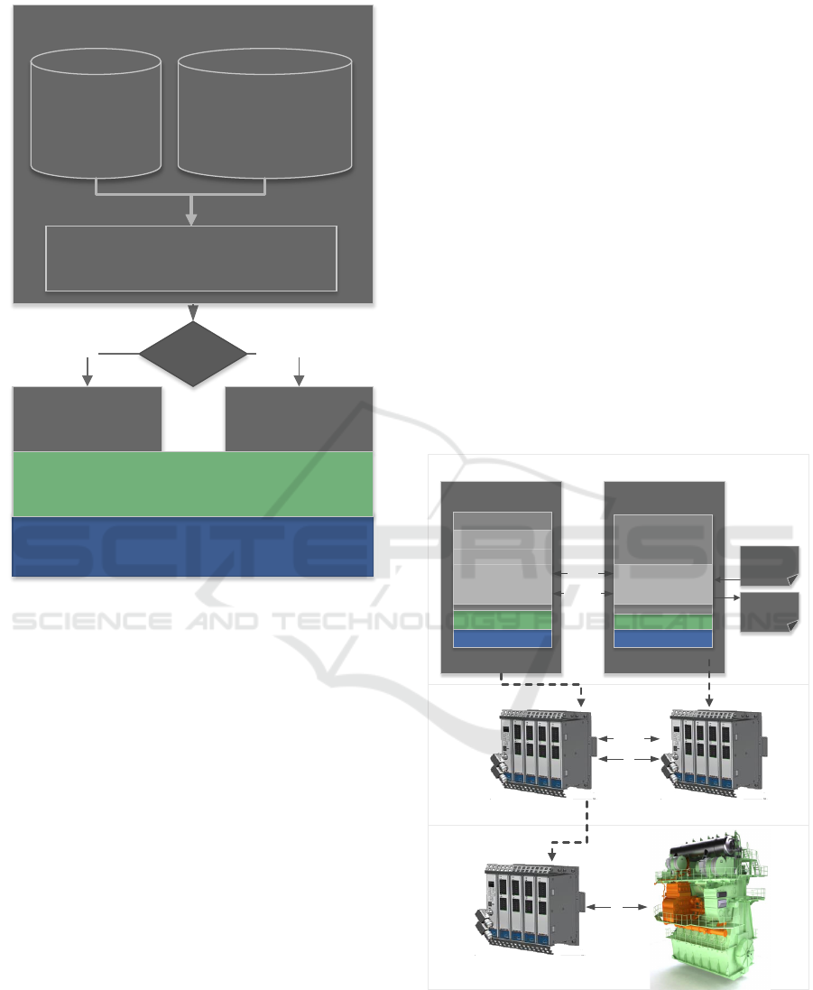
BSP
(Board Support Package)
x86-Core Embedded Core
Cross Compiler
SIL HIL & Target
Application Environment
RTOS
(Real Time Operating System)
Control
Component
Library
DSE
Execution Kernel
ODE Solver
Model Library
Control Application
Figure 2: Software Application Framework.
When challenged with a new application, con-
trol engineers at MDT often start studying the phys-
ical dynamical challenges of the system in MAT-
LAB/Simulink. When a sufficient understanding of
the system is achieved, the control strategy is formu-
lated in the software application framework and tested
against a DSE model implementation of the MAT-
LAB model. DSE is designed with HIL execution in
mind, and while it can simulate complex CT systems,
the models implemented are often at a lower abstrac-
tion level than e.g. the MATLAB models.
3.2 WHS Model
The WHS model is divided into a control algorithm
created in the software application framework and
a model of the physical components in DSE. The
control algorithm is created as a component in the
controller EGRCU along side the additional compo-
nents that comprise the entire engine control. The
control model consists of a Proportional Integral
(PI)-controller regulating the ’Receiving Tank Level
Valve’ set-point from the ’Process Water Receiving
Tank’ level sensor feedback. Besides controlling the
receiving tank level, the control algorithm also has to
ensure that transitions between states in the system is
possible, according to signals from engine operators
and the WTS control system. This control strategy is
formulated in a state-machine running in the EGRCU.
The DSE model describes the pressures and flow of
all the components illustrated in Figure 1. The model
resembles the preliminary model developed in MAT-
LAB but without details such as pressure build-up in
piping, water accumulation in components and pres-
sure loss over valves. The main purpose of the DSE
is to test the control strategy, ensuring that all state
transitions are possible and that the regulator works
correctly. To prepare for HIL simulation, the DSE
model is placed in a separate controller called the En-
gine Simulation Unit (ESU), shown in Figure 3. The
ESU controller is installed in the HIL platform as a
representation of the real engine. Data exchange be-
tween the EGRCU and ESU imitate the actual com-
munication with the real engine through analog and
digital IOs. In SIL, a software implementation of vir-
tual IOs and network simulate the communication.
SIL Simulation Manager – Developer PC
EGRCU
(EGR Control Unit)
Share Library (.SO)
ESU
(Engine Simulation Unit)
Share Library (.SO)
BSP (x86)
RTOS (x86)
Application
Component X
Component Y
WHS Control
BSP (x86)
RTOS (x86)
Application
DSE
WHS Physics
Virtual I/O
Network
Simulation
Configuration
Simulation
Results
HIL Simulation – HIL Test Bench
EGR Control Unit Engine Simulation Unit
Target – Engine Test Bench
EGR Control Unit
I/O
Network
I/O
Figure 3: SIL WHS Simulation setup.
3.3 Simulation and Verification Process
SIL simulation is achieved by compiling controllers
to an x86 platform and into shared libraries. The
SIMULTECH 2017 - 7th International Conference on Simulation and Modeling Methodologies, Technologies and Applications
76
shared libraries are executed by a simulation man-
ager ensuring temporal execution and correct data ex-
change between controllers. How the embedded con-
trol software has been adapted to enable determinis-
tic simulation has been described in (Pedersen et al.,
2016) and will not be further explained in this paper.
A simulation scenario is provided to the DSE model
through a simulation configuration file and the results
are delivered in a simulation results file.
When the system has been properly tested in the
SIL environment, the models are moved to the HIL
platform by cross-compiling to the embedded system.
On the HIL test bench additional tests of computation
overhead, communication and additional temporal is-
sues are performed.
For final testing, an engine test bench is physi-
cally available at the MDT research center in Copen-
hagen. Only a single test bench is available due to
the immense cost and sheer size of the engine. Avail-
able time-slots on the test engine are very limited and
extremely costly, due to the fuel consumption and
amount of operators required, so the proper modelling
and testing of the previous steps is desirable.
3.4 Simulation Evaluation
The SIL simulation was used to develop a function-
ing PI controller that regulates the process water tank
level and a state machine for actuating valves and
pumps according to a number of states for starting
and stopping the WHS system. The system was
tested on the HIL test bench, ensuring that the systems
worked properly on the controller hardware. Finally,
a test session was performed on the engine test bench.
This test showed that the PI controller worked as in-
tended, however, an unsuspected situation occurred
when stopping the WHS system.
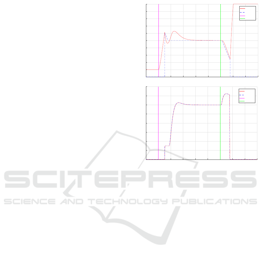
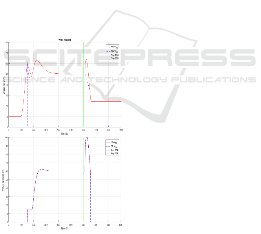
Figure 4 shows the results of running the initial
control strategy on the real system. After 100 seconds
the EGR control system ordered the WHS system to
prepare for EGR operation. Then after 50 seconds the
state-machine was finished starting different pumps
and opening of valves. At this point the Process Wa-
ter Receiving Tank (PWRT) control is fully engaged.
The bottom figure in 4 shows how the Receiving Tank
Level Valve (RTLV) is regulated to redirect water
from the process circuit to the WTS for cleaning and
stabilizing the PWRT level. The top figure in Figure 4
shows the water level in the PWRT and how it became
stable after a transient period, proving that the PWRT
control worked correctly during WHS operation. Ves-
sels are not always required to use EGR, so shut-down
of the system should be possible during engine oper-
ation. After 600 seconds a command from the engine
0 100 200 300 400 500 600 700 800 900
Time [s]
0
10
20
30
40
50
60
70
80
90
100
Water level [%]
WHS control
PWRT
FB
PWRT
SP
Start EGR
Stop EGR
0 100 200 300 400 500 600 700 800 900
Time [s]
0
10
20
30
40
50
60
70
80
Valve opening [%]
RTLV
FB
RTLV
SP
Start EGR
Stop EGR
Figure 4: WHS Control results.
operator was ordered, from an operating panel, for the
EGR system to shutdown and WHS to stop operation.
The state machine started emptying the tank to reach
a stable offline level around 20-25% in the tank. At
676 seconds a behaviour not seen in either the SIL or
HIL simulation was observed. When the WHS system
started, water in the WMC started to accumulate grad-
ually. At a point in time an equilibrium was achieved
due to increased water pressure resulting in a consis-
tent flow through the WMC (without increased water
accumulation in the WMC as a consequence). During
shutdown, when the desired water level in the PWRT
was achieved and RTLV control stopped, the accumu-
lated water in the WMC started to flow to the PWRT
tank. As seen in Figure 4, the amount of residual wa-
ter in the WMC is so large that it overfills the PWRT.
From the engine test bench it was discovered that
the controller actuating the RTLV was working prop-
erly, but the state-machine was not properly handling
the emptying of the WMC. Engine tests are very
costly and MDT would like to investigate if a more
efficient development process can be achieved. In
the DSE model used for development of the state-
machine, the accumulation of water in the WMC had
not been modelled. To improve the control strategy of
the WHS, a higher-fidelity model should be used. In-
stead of simply extending the DSE model to include a
Distributed Co-Simulation of Embedded Control Software with Exhaust Gas Recirculation Water Handling System using INTO-CPS
77

more detailed WMC model, a co-simulation solution
was chosen (Gomes et al., 2017). The co-simulation
should not only include a detailed WMC model but be
so generic that changes to the system layout and more
advanced models of components can be easily imple-
mented. The argument for the choice of co-simulation
is given in the following section.
4 TARGETING CO-SIMULATION
The software application framework and DSE is cen-
tral for development because they are designed for the
target platform of the final system, and directly enable
validation through both SIL and HIL. Keeping this in
mind it is rational to keep the control systems in the
framework. However, there are a number of options
for enhancing physics modelling that would be bene-
ficial:
• Porting the controller software to a notation that
can be used in the MATLAB environment, where
it is easier to express the physical model. This
would however, just shift the issue to the con-
troller, that then needs to be ported back to the
software application framework.
• Enhancing the physical model in DSE, while the
standard approach, it is more time consuming than
using a dedicated modelling tool like MATLAB,
but it enables faster simulation speeds.
• Use a generic solution that enables co-simulation
between the control system expressed in the soft-
ware application framework and a physical mod-
elling tool like MATLAB. This will not require
any changes to software development at MDT, but
would enable physical models to be created using
the desired modelling tool. It would potentially
run slower than a complete model expressed in
DSE but would be more flexible. This solution
would make the representation of the physical dy-
namics more detailed in SIL simulation. The co-
simulation model would not be able to run on the
HIL platform, however. The purpose of the HIL
test is not to test functionality already verified in
the SIL simulation, but to ensure computational
overhead and investigate temporal aspects.
The latter approach was chosen because it is
generic and it allows well known modelling tools in
the physical domain to be used. To interface between
models, the FMI is used, which provides a standard-
ised model interface. The last constraint on the co-
simulation is that it needs to be performed across ar-
chitectures and platforms. The software application
framework is required to run as a Linux 32bit pro-
cess. The reason for this is, as previously mentioned,
because the framework is developed to build directly
to the embedded system which is a 32bit architec-
ture. It is also a requirement that the physical mod-
elling environment be a Windows 64bit application.
The control developers working in e.g. MATLAB do
so in Windows 64bit and management-wise, introduc-
ing co-simulation to the current tool-chain would be
preferable. Another reason for the choice of deviation
in platform is the lack of 32bit support for MATLAB
on Linux.
It must be possible to run the simulation using
Linux 32bit for the software application framework
and Windows 64bit for MATLAB. Therefore a solu-
tion is to use the free FMI COE from the INTO-CPS
research project since it supports both. However, the
co-simulation cannot span architectures or platforms.
Therefore an extension is presented in section 5.1 that
enables co-simulation in a distributed setting, span-
ning both architectures and platforms.
4.1 Functional Mock-up Interface
FMI is a tool independent standard developed within
the MODELISAR project (ITEA Office Association,
2015). It supports both model exchange and co-
simulation and exists as Version 1, released in 2010
and Version 2, released in 2014. It was developed to
improve exchange of simulation models between sup-
pliers and Original Equipment Manufacturers (OEM).
The standard describes how simulation units are to be
exchanged as ZIP archives called a Functional Mock-
up Unit (FMU) and how the model interface is de-
scribed in an XML file named modelDescription.xml.
The functional interface of the model is described as
a number of C functions that must be exported by the
library that implements the model inside the FMU.
Since the FMU only contains a binary implementa-
tion of the model it offers some level of intellectual
property protection. The focus of this work is on co-
simulation, where each FMU is capable of participat-
ing in a co-simulation without the need of an external
solver, i.e. each FMU includes the required solvers
needed for simulation.
4.2 The INTO-CPS Tool Chain
While individual tools and formalisms for the de-
velopment of controllers, including simulation, test-
ing and code generation, are very mature, the de-
sign workflow is only partially integrated. The Hori-
zon 2020 project INTO-CPS (Fitzgerald et al., 2015;
Fitzgerald et al., 2016) aims at closing this gap, by
SIMULTECH 2017 - 7th International Conference on Simulation and Modeling Methodologies, Technologies and Applications
78
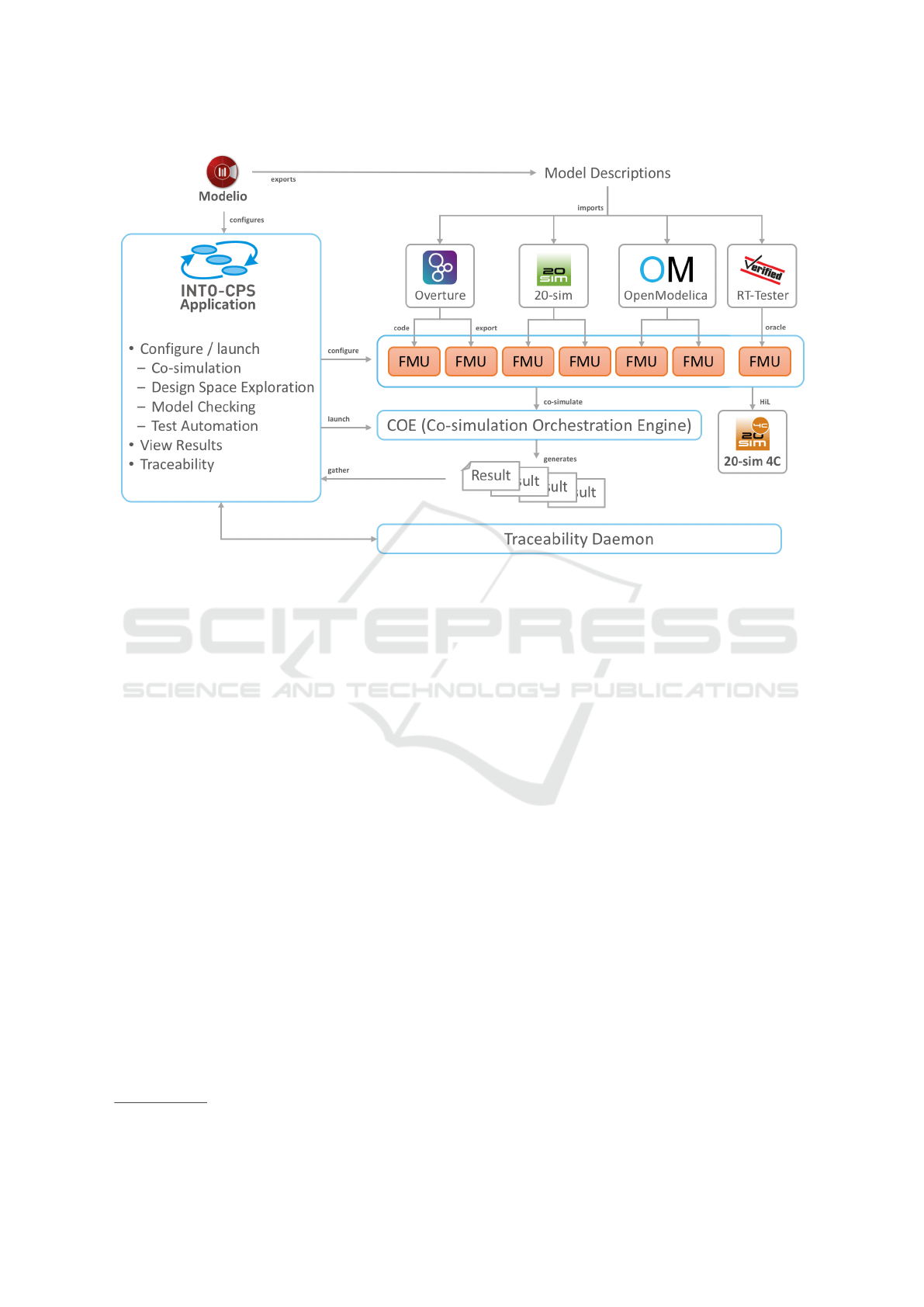
Figure 5: The INTO-CPS Tool Chain.
creating an Integrated Tool-chain for the model-based
design of Cyber-Physical Systems (Larsen et al.,
2016). The chain of tools are connected as illus-
trated in Figure 5, moving all the way from require-
ments to final realisations (Bandur et al., 2016). One
of the core tools of this chain is a newly developed
COE, which is a fully FMI 2.0 co-simulation com-
pliant Master supporting both fixed and variable step
size simulations. It was decided to use FMI as the in-
terface for the different simulation and testing tools,
since it is a mature standard
2
created in the MOD-
ELISAR project (ITEA Office Association, 2015)
with an active community.
The COE is developed in a combination of Java
and Scala, which makes it multi-platform and pro-
vides the simulation service through HTTP. Currently,
two methods for time-stepping are implemented; one
for fixed time steps, and one for variable time steps.
The COE is capable of switching on stability check-
ing as well as using parallelism (Thule and Larsen,
2016). In addition to the baseline tools incorpo-
rated inside the tool chain, a number of other mod-
elling and simulation tools have been tested with the
COE. This includes both commercial tools such as
Dymola, Modelon, SimulationX and Unity as well as
additional open source tools such as 4Diac. While
the COE is multi-platform it does not directly sup-
port mixed-architecture (combinations of 32bit and
2
http://fmi-standard.org
64bit architectures) or mixed-platform (combinations
of e.g. Windows and Linux) simulations as required
for the WHS system as discussed next in section 5.
5 WHS CO-SIMULATION
To co-simulate the WHS from section 3 using FMI, it
is required that both constituent models must support
FMI, and that a suitable orchestration engine that sup-
ports FMI and the required platform and architecture
combination is available. Since no such simulator is
available an extension to the COE is described in sec-
tion 5.1. To enable FMI for the constituent models,
an extension was developed for the MDT software
application framework which has been published in
(Pedersen et al., 2016; Pedersen et al., 2015). The
model of the WHS is exported from MATLAB to
an FMU using the Modelon FMI Toolbox for MAT-
LAB/Simulink (Modelon, 2015). The complete co-
simulation model is shown in section 5.2, and evalu-
ated in section 5.3.
5.1 Distributed COE Extension
To enable multi-architecture co-simulation, the chal-
lenge of mixing 32bit and 64bit code needs to be ad-
dressed. Essentially, two processes with inter-process
Distributed Co-Simulation of Embedded Control Software with Exhaust Gas Recirculation Water Handling System using INTO-CPS
79
COE
Factory
FMU
*.fmu
Distributed Factory
Proxy FMU
Host 1
Daemon
FMU
*.fmu
Host 2
Transferred
Figure 6: Distributed Extension Overview.
communication are required by the host system to re-
alize this, where one of them acts as the simulation
master. A similar challenge arises when different plat-
forms need to interact in a co-simulation.
An extension to the COE was developed that is
capable of both simulating across architectures and
platforms. The solution chosen was to utilize an ex-
tension point in the COE that allows a custom factory
to be used for FMU instantiation. An overview of the
extension is realized and shown in in Figure 6. The
COE uses the distributed factory to instantiate FMUs
that require execution with a different host configura-
tion, either architecture or platform deviation.
The extension is realized using Java-Remote
Method Invocation (JAVA-RMI) to provide cross-
platform communication (JavaRMI, 2004). It consists
of a distribution factory and an FMU proxy that is
plugged into the COE. It uses a daemon that must run
on the remote host to provide a service that enables
the COE to remotely load and control FMUs. The
COE configuration is also extended to specify which
remote daemon a specific FMU should be executed
by. When a co-simulation is started the COE will
communicate with the specified remote daemons to
configure the co-simulation by first pushing FMUs to
the remote daemons that then in turn load and setup a
communication channel for the loaded FMUs. These
will then be connected to the FMU proxy in the COE,
which is responsible for handling remote communi-
cation.
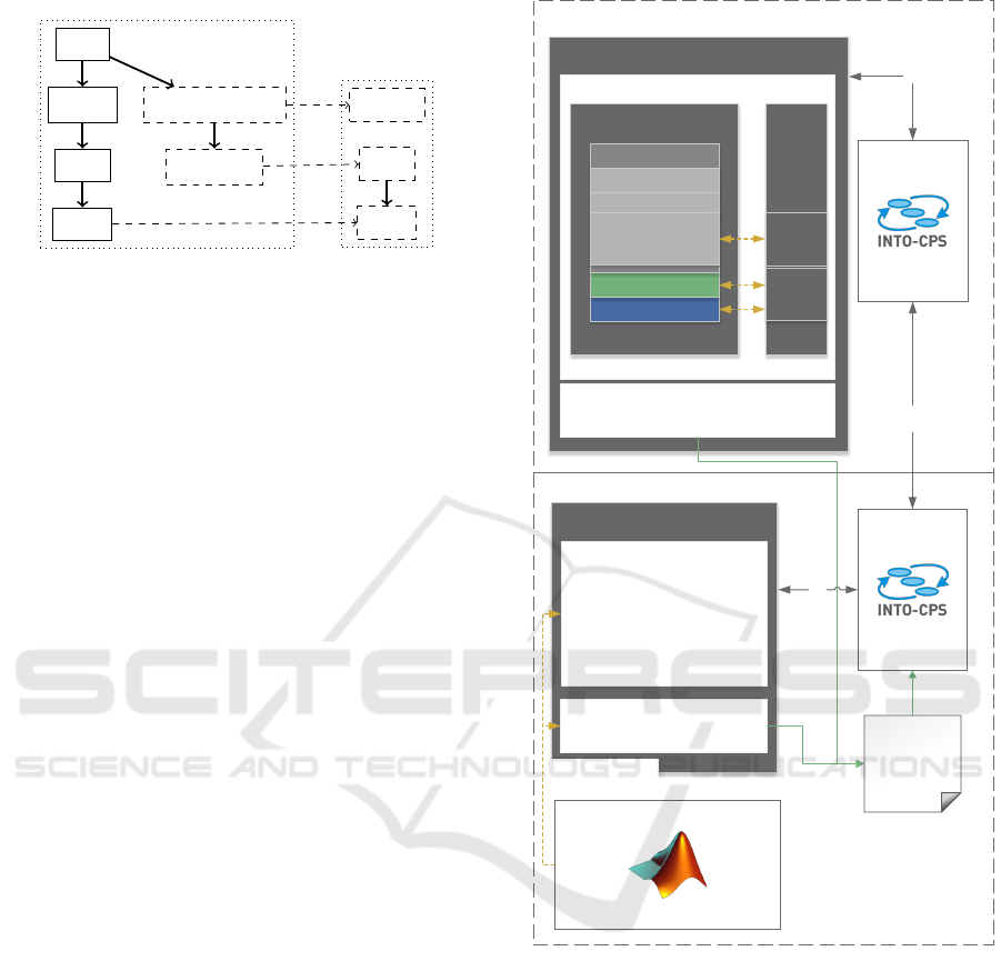
5.2 Co-Simulation Setup
The co-simulation setup is illustrated in Figure 7. The
master COE is running on the Windows host, and the
COE-deamon on the Linux host. A JSON configura-
tion file describes the co-simulation setup to the COE.
The configuration file tells the COE where the FMU-
archives are located and on which host-ip they should
be executed. The configuration file also contains in-
formation about connections between the inputs and
outputs of the FMUs, parameters and simulation al-
Windows Host
Linux Host
FMU
Distributed
COE
Daemon
FMI Wrapper
Shared Library Linux 32-bit
EGRCU
(EGR Control Unit)
Share Library (.SO)
BSP (x86)
RTOS (x86)
Application
Component X
Component Y
WHS Control
FMI API
Data
Exchange
Simulation
Execution
ModelDescription.xml
FMU
ModelDescription.xml
Code Generation
(Modelon FMI-Toolbox)
WHS Physics Model
Dynamic-link library Win 64-bit
WHS Physics Model
MATLAB
COE
Master
FMI
FMI
JAVA
RMI
Config.json
Figure 7: Co-Simulation Configuration.
gorithm: variable/fixed time step.
The WHS MATLAB model is code generated into
an FMU using the Modelon FMI toolbox for MAT-
LAB/simulink. The toolbox compiles the MATLAB
model to a 64-bit DLL including the FMI-API and
auto-generates the model description XML defining
the interface to the FMU. The control system FMU
has been created by wrapping the FMI Application
Programming Interface (API) around the SIL simula-
tion and compiling it to a Linux 32-bit shared library.
The simulation can access the RTOS for scheduling
and a hook to the clock in the BSP, all described in
(Pedersen et al., 2016). Accessing the variables of the
WHS control is done through a proxy interface that
provides pointers to internal variables to be manipu-
SIMULTECH 2017 - 7th International Conference on Simulation and Modeling Methodologies, Technologies and Applications
80
lated. Furthermore, the proxy interface introduces a
conversion layer between internal types such as FIX-
POINT16 and FMI-types. The SIL simulation only
includes the EGRCU controller, which contains the
WHS control. The ESU controller, containing the
DSE models, has been replaced with the MATLAB
model in the co-simulation.
The simulation is initiated through the COE and
results delivered in Comma-Separated Values (CSV)
format on the Windows host.
5.3 Co-Simulation Evaluation
Figure 8 shows the simulation results with the pro-
posed Co-Simulation setup, where the DSE physical
model has been replaced with the more detailed MAT-
LAB model. Being able to anticipate the behaviour
of the accumulated water in the Water Mist Catcher,
it is now possible to address it and to modify the state
machine accordingly to control the components in a
more appropriate way during WHS shutdown. The
first 600 seconds show the same response as in Fig-
ure 1. However, the new state machine now ensures
Figure 8: WHS Control results.
that the WMC is drained before shutting down RTLV
control. This prevents the water level in the PWRT
from overflowing, but instead stabilize at a desired
level of approximately 20-25%.
6 CONCLUDING REMARKS
This paper shows how the control development pro-
cess at MAN Diesel & Turbo could benefit from in-
troducing co-simulation. The conventional approach,
where control algorithms and strategy are formulated
using simplified models of the physical dynamics, is
not always able to properly represent the complex-
ity of the system. Importantly, with this approach,
defects are typically not found before moving to the
expensive engine test bench. With the co-simulation
approach proposed in this paper, higher-fidelity con-
stituent models of physical dynamics, formulated in
dedicated tools, can be simulated together with a SIL
simulation of the control software, at an earlier stage
of development. In the example presented, the ac-
cumulation of water in a water mist catcher was ne-
glected in the initial model, essentially resulting in
a water tank overflow during shutdown. With the
co-simulation, a more detailed model, formulated in
MATLAB, could be used for developing a working
control strategy. Had the co-simulation been used for
initial control development, the issues seen on the test
engine would likely have been discovered at an earlier
stage, saving money and time.
The main challenge enabling co-simulation at
MDT was the deviation in both OS platform and hard-
ware architecture of the simulation tools used. The
SIL simulation of the control software is constrained
to a 32-bit Linux platform and the MATLAB environ-
ment was required to run on a 64-bit Windows plat-
form due to change management concerns. In coop-
eration with the INTO-CPS-project, the INTO-CPS
Co-simulation Orchestration Engine for executing co-
simulations complying with the Functional Mock-up
Interface standard was adapted to enable distributed
co-simulation. With the distributed COE it was possi-
ble to conduct the co-simulation despite the platform
and architecture deviation.
Besides the promising results shown in this paper,
additional benefits form the INTO-CPS co-simulation
tool chain are anticipated. The extensions developed
to the MDT frameworks and development processes
enable not only co-simulation of the EGR system, but
also of any other system to be developed in the future
by MDT, with minimal effort. In the future it will
be explored when it makes sense to also make use of
more capabilities from the INTO-CPS tool chain.
Distributed Co-Simulation of Embedded Control Software with Exhaust Gas Recirculation Water Handling System using INTO-CPS
81

In the EGR Water Handling System presented
here, a subsystem called Water Treatment System is
delivered by an MDT OEM and neither modelled nor
controlled by MDT. One of the main advantages of
the Functional Mock-up Interface standard used by
INTO-CPS is that models are exchanged on a binary
level offering protection of intellectual property. One
of the future ambitions is to be able to share models
with OEMs so systems like the WHS and WTS can be
simulated together, improving both companies prod-
ucts. Part of the high-fidelity models developed at
MDT are very complex and require time to simulate,
especially if co-simulated with several other models.
One of the additional advantages of the distributed co-
simulation is that the simulation process can be par-
allelized and perhaps distributed to centralized high-
performance hardware. This could potentially speed
up simulation execution times and enable more ad-
vanced system investigations, previously deemed too
time consuming. Initial work on using the COE in
a cloud setting has already been initiated, in particu-
lar in relation to design space exploration in situations
where there is large room for different alternative so-
lutions.
ACKNOWLEDGEMENTS
The work presented here is partially supported by the
INTOCPS project funded by the European Commis-
sion’s Horizon 2020 programme under grant agree-
ment number 664047. In addition we would like to
thank Victor Bandur for inout on an earlier draft of
this article.
REFERENCES
Bandur, V., Larsen, P. G., Lausdahl, K., Thule, C.,
Terkelsen, A. F., Gamble, C., Pop, A., Brosse, E.,
Brauer, J., Lapschies, F., Groothuis, M., Kleijn, C.,
and Couto, L. D. (2016). INTO-CPS Tool Chain User
Manual. Technical report, INTO-CPS Deliverable,
D4.2a.
Fitzgerald, J., Gamble, C., Larsen, P. G., Pierce, K., and
Woodcock, J. (2015). Cyber-Physical Systems de-
sign: Formal Foundations, Methods and Integrated
Tool Chains. In FormaliSE: FME Workshop on For-
mal Methods in Software Engineering, Florence, Italy.
ICSE 2015.
Fitzgerald, J., Gamble, C., Payne, R., Larsen, P. G.,
Basagiannis, S., and Mady, A. E.-D. (2016). Collab-
orative Model-based Systems Engineering for Cyber-
Physical Systems – a Case Study in Building Automa-
tion. In INCOSE 2016, Edinburgh, Scotland.
Fitzgerald, J., Larsen, P. G., and Verhoef, M., editors
(2014). Collaborative Design for Embedded Systems
– Co-modelling and Co-simulation. Springer.
Gomes, C., Thule, C., Broman, D., Larsen, P. G., and
Vangheluwe, H. (2017). Co-simulation: State of the
art. Technical report.
IMO, I. M. O. (2015). MARPOL ANNEX VI and NTC
2008 with Guidelines for Implementation - Supple-
ment. Technical Report September 2015.
ITEA Office Association (2015). Itea 3 project 07006
modelisar. https://itea3.org/project/modelisar.html.
(Visited on 12/06/2015).
JavaRMI (2004). Java remotemethodinvocation specifica-
tion 1.5.0. http://java.sun.com/j2se/1.5/pdf/rmi-spec-
1.5.0.pdf.
Kleijn, C. (2006). Modelling and Simulation of Fluid Power
Systems with 20-sim. Intl. Journal of Fluid Power,
7(3).
Larsen, P. G., Fitzgerald, J., Woodcock, J., Fritzson, P.,
Brauer, J., Kleijn, C., Lecomte, T., Pfeil, M., Green,
O., Basagiannis, S., and Sadovykh, A. (2016). Inte-
grated Tool Chain for Model-based Design of Cyber-
Physical Systems: The INTO-CPS Project. In CPS
Data Workshop, Vienna, Austria.
MAN Diesel & Turbo (2016). Emission Project Guide,
MAN BW Two-stroke Marine Engines. Technical re-
port, MAN Diesel & Turbo.
MathWorks (2011). http://www.mathworks.com. Matlab
official website.
Modelon (2015). http://www.modelon.com/products/fmi-
tools/fmi-toolbox-for-matlabsimulink/. Modelon FMI
Toolbox for MATLAB/Simulink official website.
Pedersen, N., Bojsen, T., Madsen, J., and Vejlgaard-
Laursen, M. (2016). FMI for Co-Simulation of Em-
bedded Control Software. In Link
¨
oping Electronic
Conference Proceedings, number 124, pages 70–77.
Pedersen, N., Madsen, J., and Vejlgaard-Laursen, M.
(2015). Co-Simulation of Distributed Engine Control
System and Network Model using FMI and SCNSL.
10th IFAC Conference on Manoeuvring and Control
of Marine Craft MCMC 2015, 48(16):261–266.
SYST
`
EMES, D. (2017). https://www.3ds.com/products-
services/catia/products/dymola. 3ds official website.
Thule, C. and Larsen, P. G. (2016). Investigating con-
currency in the co-simulation orchestration engine
for into-cps. In Alexander S. Kamkin, A. K. P.
and Terekhov, A. N., editors, Preliminary Proceed-
ings of the 10th Anniversary Spring/Summer Young
Researchers’ Colloquium on Software Engineering
(SYRCoSE 2016), Krasnovidovo, Russia, May 30-
June 1, 2016), pages 223–228. ISP RAS.
SIMULTECH 2017 - 7th International Conference on Simulation and Modeling Methodologies, Technologies and Applications
82
