
Tool Support to Automate Transformations from SBVR to UML Use
Case Diagram
Imane Essebaa and Salima Chantit
Computer Laboratory of Mohammedia (LIM), Faculty of Sciences and Techniques Mohammedia,
Hassan II University of Casablanca, Mohammedia, Morocco
Keywords:
Model Driven Architecture, Model Transformation, Semantic Business Vocabulary and Business Rules, UML
Use Case Diagram.
Abstract:
Model transformation becomes a very important technique in software engineering as it helps to guarantee
traceability between models and develop software applications quickly, In this context, the purpose of this
work is an approach that allows generating UML Use Case Diagram (UCD) from Semantic Business Vocabu-
lary and Business Rules (SBVR) which is a standard introduced by OMG that can be used to capture software
requirements in structured English. The paper gives a set of rules that map SBVR element into UCD elements.
This approach is a part of our works that focus on automating Model Transformations to generate the applica-
tion code following standards of Model Driven Architecture approach. Particulary we use SBVR standard and
UCD to model the Computation Independent Model (CIM) which is the first level of abstraction. The paper
describes also an implementation of this approach as an Eclipse plug-in that automates the transformation
rules defined using QVT language. In order to well illustrate our approach, we apply it on RentalCarAgency
system.
1 INTRODUCTION
System designing is an essential step in software de-
velopment process. It acts as a bridge between the de-
veloper, the software designer and a simple user of the
system. There exist different ways to ensure a good
analysis of system requirements. Use Case Diagram
(UCD) is an essential artefact in systems functional
requirements analysis and specification. Indeed UCD
provides a visual representation of possible interacti-
ons between system actors and their functionalities.
In order to have a good design of the system that may
be used to generate other models, it is necessary to
have a well-described requirements, that is why it is
recommended to use a structured language. In this
paper, we focus on structured English language using
SBVR.
Generating models from others using model trans-
formation rules becomes an important technique to
ensure traceability and link between system require-
ments and their design. Several approaches were pro-
posed in this context, to transform UML diagrams,
however few of them focused on generating UML dia-
grams, from structured requirements using SBVR (es-
pecially generating UCD).
Existing works concerning transformations bet-
ween SBVR and UML diagrams focused on the map-
ping to generate Class Diagram and Activity Dia-
gram. Furthermore few works have considered the
transformation from UCD to SBVR.
In this paper we propose an approach to generate
automatically UCD from SBVR. This approach is a
part of our works that aim to automate transformati-
ons between different levels of MDA, where we have
represented CIM level by SBVR and UCD. Then from
CIM, we generate other MDA levels to obtain finally
a generated application source code. Generating UCD
from SBVR ensure traceability between requirements
and other levels. In order to ensure automated trans-
formations between levels, we present in this paper
an approach that defines a set of transformation rules,
developed with QVT language that we implement in
an Eclipse plug-in.
This paper is organized as follows; section 2 gives
an overview of concepts used to implement our ap-
proach. In section 3, we discuss the related works and
in section 4, we describe the proposed approach and
its implementation. In section 5, we present the appli-
cation of the approach on a RentalCarAgency system
example and in section 6, we discuss and evaluate our
Essebaa, I. and Chantit, S.
Tool Support to Automate Transformations from SBVR to UML Use Case Diagram.
DOI: 10.5220/0006817705250532
In Proceedings of the 13th International Conference on Evaluation of Novel Approaches to Software Engineering (ENASE 2018), pages 525-532
ISBN: 978-989-758-300-1
Copyright
c
2019 by SCITEPRESS – Science and Technology Publications, Lda. All rights reserved
525
approach Finally, we finish by a conclusion and some
perspectives.
2 OVERVIEW OF CONTEXT
2.1 Model Transformation
The execution of transformations between models en-
sures traceability of links between different models.
This link is a guarantee of quality in the software de-
velopment process. The transformation process pro-
posed takes as input source models, applies transfor-
mation rules, and generate target models. This pro-
cess conforms to Model Object Facility (MOF, 2009)
which is an OMG standard that allows describing me-
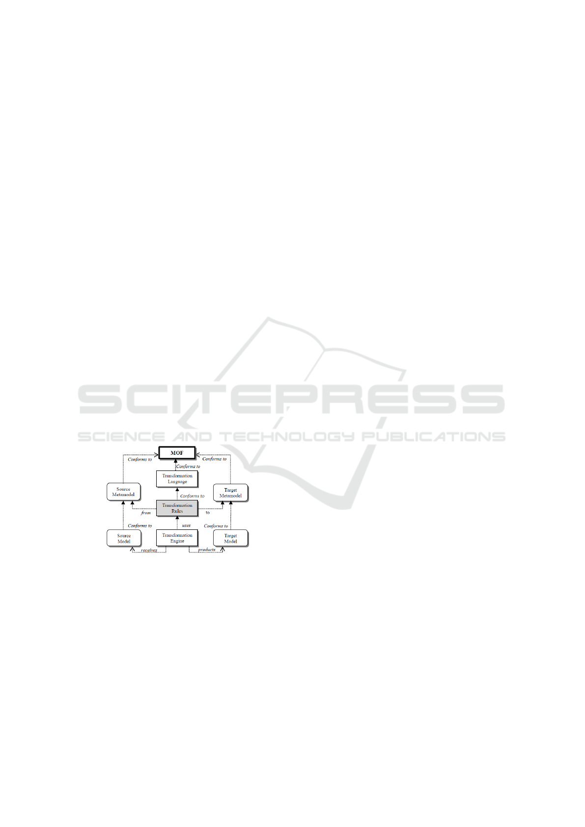
tamodels and their manipulation. Figure 1, illustrates
the process of model transformation. A model trans-
formation is like a function that takes as input parame-
ters a set of models and returns in output another set
of models. Those models, input and output, are struc-
tured by meta-models that specify the model transfor-
mation executed on models.
The MOF (Meta Object Facility) is normalized by
OMG, it allows the definition of transformation rules
and modeling languages, it also specifies the struc-
ture and syntax of meta-models. In this context, the
OMG proposes a standard transformation language
QVT(Query/view/transformation) to define transfor-
mation rules from models to models.
Figure 1: Relationship between the model transformation
and meta-models.
2.2 Query / View / Transformation
(QVT)
To implement our transformations, we have to use a
transformation language. There exist many models of
transformations language, but QVT is the unique pro-
posal of the OMG. The QVT standard defines three
model transformation languages: QVT Operational,
QVT Relational and QVT core. We chose QVT Ope-
rational because it supports bidirectional transforma-
tions, both horizontal and vertical transformations,
and ensures automatic traceability(MOF, 2009).
3 RELATED WORKS
Model Transformations are considered as an impor-
tant approach. Several works were made in this con-
text. However, most of them focused on transformati-
ons between different UML diagrams, and just a few
ones were focused on the transformations from SBVR
to UML diagrams. In this section, we present our ana-
lysis of these works:
T.Skersys and al. propose in their paper (Skersys
et al., 2014) an approach that generate well-structured
business vocabularies and rules using SBVR from the
formalized requirements specifications expressed via
Use Case diagrams. The paper propose an algorithm
that defines UML2SBVR transformations which were
implemented in MagicDraw tool. These transforma-
tions however are semi-automatic.
In their paper (Afreen et al., 2011) H. Afreen and
al. proposed an approach to extract manually Object-
Oriented informations from SBVR then to generate
Class model. The paper proposes a conception of an
eclipse plug-in called SBVR2UML that may generate
Class model but it does not contain any description
on how the link is made between these elements.We
also note that this approach does not automate trans-
formations between SBVR and UML Class Model.
Indeed the Object-Oriented informations are genera-
ted manually. Moreover, the paper defines just a con-
ception of an eclipse plug-in called SBVR2UML. We
note also that this approach does not define how to
generate other diagrams such as Sequence Diagram
or Activity Diagram.
A.Raj and al. present in their paper (Raj et al.,
2008), an approach to transform SBVR in more than
just one UML diagrams: Class Diagram and Activity
Diagram. We note that this approach describes for
each generation, the algorithm to follow in order to
get UML Diagrams. But this generation is still li-
mited as it does not, for example, define how to get
parameters of Class operations. Furthermore, in or-
der to generate Activity Diagram, the approach takes
into account just ”if-then” conditions but it does not
explain how it will be transformed and how the dia-
gram is generated.In this paper, authors consider the
SBVR standard in the CIM level of MDA, while ge-
nerated UML diagrams (Class Diagram, Activity Di-
agram and Sequence Diagram) represent the PIM le-
vel. We also note that the Activity Diagram contains
the same information as the Sequence Diagram mo-
MDI4SE 2018 - Special Session on Model-Driven Innovations for Software Engineering
526
deled differently and their use at the same level does
not add more information.
4 PROPOSED APPROACH
In this section, we present our proposed approach to
generate UCD from SBVR that represent system re-
quirements in a structured English.
4.1 CIM Level in Our Approach
The CIM level is the most abstract level in MDA ap-
proach. This level is considered as the most impor-
tant because it models system requirements, and from
this model, we can generate the other levels of MDA.
Thus, other models are affected if any changes are
made in CIM level.
In order to respect OMG recommendations to well
model CIM level and to ensure traceability between
models, we propose to represent it by an extended Use
Case Diagram generated from OMG standard SBVR.
4.2 SBVR Meta-model
The OMG standard Business Vocabulary and Busi-
ness Rules (SBVR), is a specification that was accep-
ted by the OMG in 2005. The basic idea behind
SBVR is to express requirements in a structured lan-
guage (SBV, 2008). It allows the business analyst or a
business person to express system requirements using
structured English instead of using its own language.
Using SBVR to express business requirements af-
fect a semantic to business rules and business vocabu-
lary and give more details about the system, such as
Business Management Rules that describes the inte-
raction between system elements. A meta-model di-
agram of main fragments of SBVR is presented in fi-
gure 2.
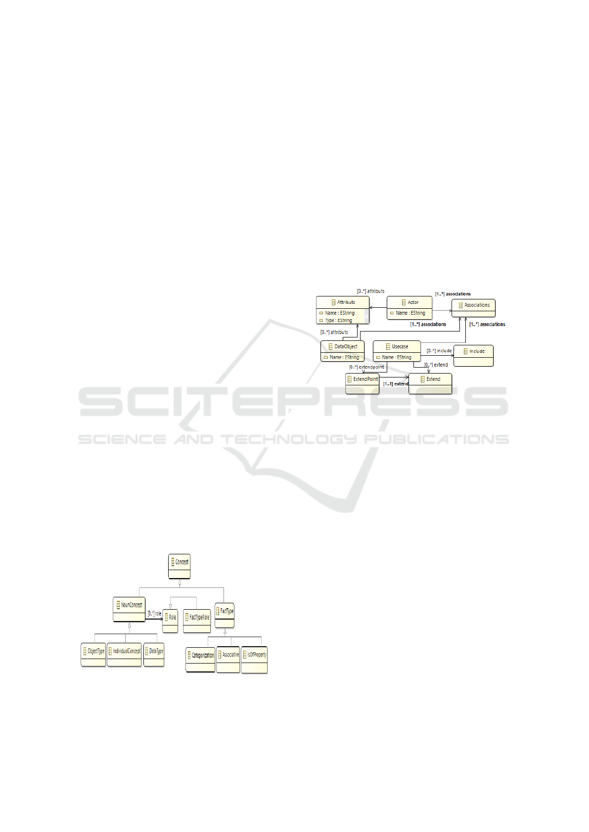
Figure 2: Main fragments of Semantic Business Vocabulary
and Business rules Meta-model.
4.3 UML Use Case Diagram
Meta-model
OMG (Object Management Group) defines a Use
Case Diagram as the specification of a set of actions
performed by a system, which yields an observable
result that is, typically, of value for one or more actors
or other stakeholders of the system (OMG, 2011).
A Use Case Diagram is such a bridge that covers
the gap between the simple user of the system and the
software designer, indeed it gives a general view of
the system, in our approach UCD is generated from
SBVR in order to ensure traceability between system
requirements and its design. A simplified version of
the meta-model of the extended Use Case Diagram is
represented in figure 3.
Figure 3: Main fragments of Use Case Diagram Meta-
model.
4.4 Transformation Rules
In this section, we will define different transforma-
tion rules that allow the automatic generation of UCD
from SBVR.
The transformation process proposed takes as in-
put source models, applies transformation rules, and
generate target models. This process conforms to
MOF (Model Object Facility) which is an OMG stan-
dard that allows describing meta-models and their
manipulation.
The Table 1 below describes transformation rules
to automatically generate UML Use Case Diagram
from SBVR.
4.4.1 Transformation Rules Description
This section gives more details on each transforma-
tion rule defined
1. IndividualConcept2System: The Individual Con-
cept that has System as a general Concept is tur-
ned into a System in UCD.
Tool Support to Automate Transformations from SBVR to UML Use Case Diagram
527
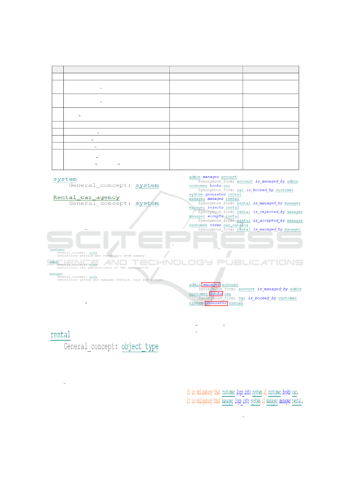
Table 1: Transformation rules to generate UML UCD from SBVR.
N Rule Source Model Target Model
1 IndividualConcept2System Individual Concept System
2 NounConcept role2Actor
Noun Concept with Role
as a general concept
Actor
3 NounConcept objectType2DataObject
Noun Concept with Object
Type as a general concept
Data Object
4 Verb AssociativeFactType2UseCase
Verb of Association
Fact Type
Use Case element
5 AssociativeFactType2Association Association Fact Type Association
6 IsObligatory BusinessRule2Include Is Obligatory Business Rule Include
7 IsPossible BusinessRule2Extend Is Possible Business Rule Extend
8 IsPermitted BusinessRule2Generalization Is Permitted Business Rule Generalization
9
IsNecessary BusinessRule2
Association UseCase DataObject
Is Necessary Business Rule
Association between
Use Case element
and Data Object
Figure 4: Examples of individual concept.
2. NounConcept role2Actor: The Noun Concept in
SBVR that has Role as a general concept is turned
into an Actor in UCD.
Figure 5: Examples of Role Noun Concept.
3. NounConcept objectType2DataObject: The
Noun Concept in SBVR that has Object Type as
general concept is turned into a DataObject in
UCD.
Figure 6: Example of Object Noun Concept.
4. Verb AssociativeFactType2UseCase: The verb in
Associative Fact Type in SBVR is turned into a
Use Case element in UCD. The Name of the Use
Case Element is a combination of the Verb and the
Noun Concept that follows the Verb in the Asso-
ciative Fact Type.
Figure 7: Example of Association Fact Type.
5. Associative FactType2Association: The Associa-
tive Fact Type between two Noun Concepts is tur-
ned into an Association between the correspon-
ding Use Case Element and an Actor, or between
Use Case Element and DataObject if it exists.
Figure 8: Examples of Association Fact Type verb.
6. Is Obligatory BusinessRule2Include: It
Is Obligatory business rules are turned into
Include association between Use Case Elements
generated from the two Associative Fact types
used in the rule. The Include association is
redirected from the Use Case Element generated
from the second Associative Fact Type to the Use
Case Element generated from the fist Associative
Fact Type.
Figure 9: Examples of Is Obligatory Business Rule.
MDI4SE 2018 - Special Session on Model-Driven Innovations for Software Engineering
528
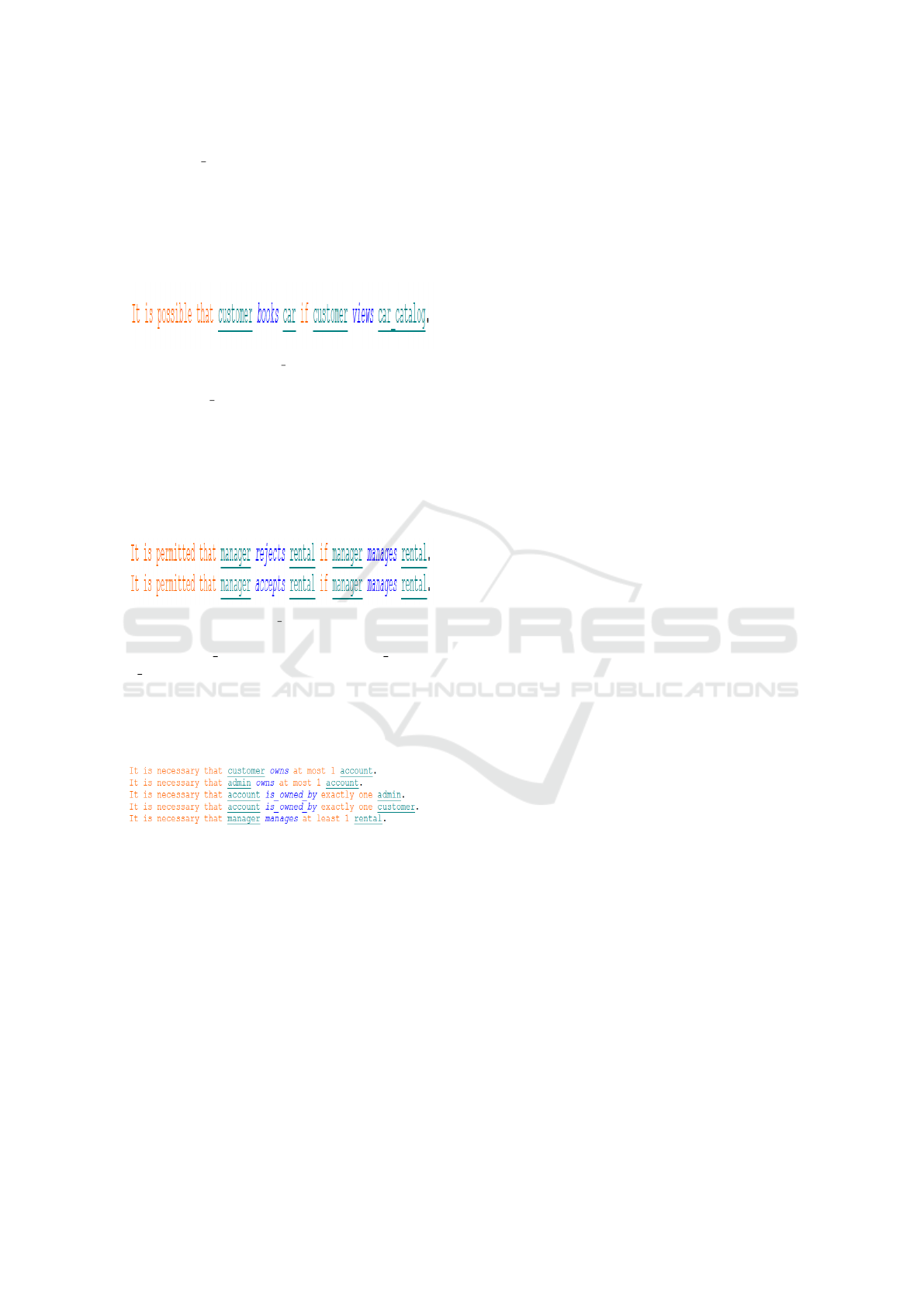
7. IsPossible BusinessRule2Extend: It Is Possible
business rule is turned into Extend association if
the rule is used with two Associative Fact Type.
The Extend association is redirected from the Use
Case Element generated from the first Associa-
tive Fact Type to the Use Case Element generated
from the second Associative Fact Type.
Figure 10: Example of Is Possible Business Rule.
8. IsPermitted BusinessRule2Generalization: It Is
Permitted business rule is turned into Generaliza-
tion association if the rule is used with two As-
sociative Fact Types. The Generalization associa-
tion is redirected from the Use Case Element ge-
nerated from the first Associative Fact Type to the
Use Case Element generated from the second As-
sociative Fact Type.
Figure 11: Example of Is Permitted Business Rule.
9. IsNecessary BusinessRule2Association UseCase
DataObject: The association between a UseCase
element and a DataObject element is generated
from Is Necessary Business Rule between system
generation fact type and a corresponding fact type
that will be generated into the UseCase element.
Figure 12: Example of is necessary Business Rule.
4.5 Implementation of Our Approach
To implement our approach, we need tools that al-
low creating input elements (Business Vocabulary and
Business Rules). After analyzing and testing exis-
ting tools, we found that the unique tool that supports
SBVR is an eclipse plug-in called Vetis which was
implemented for an old version of Eclipse to support
SBVR standard. Concerning UML editors we choose
Papyrus because it supports all UML diagrams ele-
ments. According to this, we choose to implement
our solution as an Eclipse plug-in to benefit from the
existing tools and also to facilitate the use of our im-
plemented solution by designers and developers.
4.5.1 Papyrus Modeling Tool
Papyrus is an Open Source UML tool based on
Eclipse. It was developed by the Laboratory of Model
Driven Engineering and Embedded Systems and can
be used as a standalone tool or as an Eclipse Plug-in.
Papyrus is designed to be easily extensible because it
is based on UML profile. In our approach, we used
Papyrus as an Eclipse plug-in that we extend to sup-
port DataObject elements in Use Case Diagram. As
papyrus is based on EMF (Eclipse Modeling Frame-
work) tool that allows creating UML diagrams, we
start by extending the EMF plug-in to define DataOb-
ject element and its specifications to be used by Use
Case Diagram. Then, we configure Papyrus in order
to add DataObject element in Use Case Diagram, so
that it can be accessible from the palette menu.
4.5.2 Vetis Plug-in
Vetis tool was implemented to support transforma-
tions from SBVR to UML&OCL. It was based on
Eclipse platform 3.4.1 and it supports UML 2.0.
SBVR 1.0 and ATL. In our approach we use Vetis
plug-in to recognize SBVR elements and their struc-
ture and to benefit from the editor of SBVR standard.
4.5.3 Our Eclipse Plug-in
Plug-in is a software component used in computing
that adds a specific features to an existing compu-
ter program. The plug-in we have developed, defi-
nes transformations rules based on QVT (Query View
transformation). These rules are automatically exe-
cuted from a Java program. The plug-in takes as in-
put a Papyrus Project that contains Business Vocabu-
lary and Business Rules expressed using SBVR stan-
dard. The ”Transforms” feature added in the menu,
allow the execution of transformations defined auto-
matically. As result of transformations, an out folder
is created in the Papyrus Project that contains the out-
put generated Use Case Diagram. The figure 13 below
shows the ”transforms” menu and the architecture of
Papyrus project.
5 CASE STUDY
In order to illustrate our approach and the transfor-
mation rules defined, this section shows how to apply
the approach on a RentalCarAgency application. The
example is described as follow: The application to re-
alize must guarantee the following services:
• Visualization of available cars.
Tool Support to Automate Transformations from SBVR to UML Use Case Diagram
529
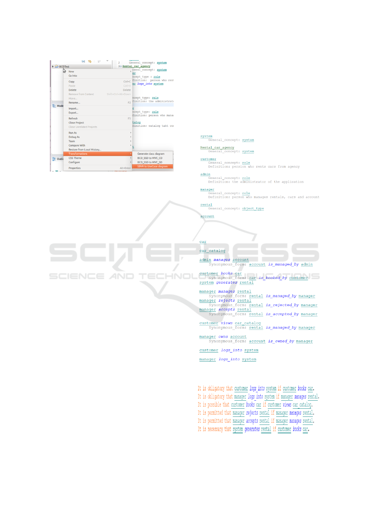
Figure 13: Papyrus Project Architecture and ”Transforms”
menu.
• Customers subscription.
• Booking of cars.
• Visualization of reservations.
• Management of reservations (accept/decline).
• Management of cars.
• Management of customer accounts.
• Management of accounts Managers.
The application has three users profiles that have dif-
ferent privileges :
• Customer: A person who can view the cars avai-
lable in the agency, rates and promotions and may
subscribe. Once registered, the visitor becomes a
client of the Agency. A client must authenticate in
the system to search for available cars and book a
car by indicating the reservation date and time.
• Manager: A Manager must also authenticate to
view all cars, add, edit or remove cars and view
the bookings made by customers waiting for vali-
dation to decide to accept or refuse them.
• Administrator: Once authenticated into the sy-
stem, the administrator has the privilege of mo-
difying and deleting a customer account, as well
as the management of managers account (add,
change or delete).
We can define some management rules as below:
• A customer can rent several cars.
• A car can be rented by 0 or several customers.
• A manager can manage 1 or more cars.
• A car is managed by 1 or more managers.
• An administrator can manage 1 or several custo-
mer accounts.
• An administrator can manage 1 or more account
managers.
After analysing the application requirements, the
designer should standardize the requirements with
Structured English using Business Vocabulary and
Business Rules with the OMG standard SBVR, the
first step is to define the vocabulary of the applica-
tion and specify General Concept for each element.
A part of Business vocabulary is defined in the figure
14. After applying the transformation rules already
described in previous sections we got the following
results presented in table 2.
Figure 14: Papyrus Project Architecture and ”Transforms”
menu.
Figure 15: Example of Business Vocabulary of RentalCa-
rAgency application.
Figure 16: Example of Business Rules of RentalCarAgency
application.
MDI4SE 2018 - Special Session on Model-Driven Innovations for Software Engineering
530
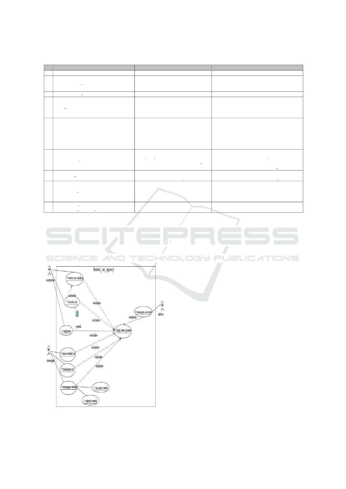
Table 2: Application of transformation rules on RentalCarAgency system.
N Rule Source Model Target Model
1 IndividualConcept2System RentalCarAgency RentalCarAgency System
2 NounConcept role2Actor
- Customer
- Manager
- Admin
- Customer
- Manager
- Admin
3 NounConcept objectType2DataObject - Rental - Rental
4 Verb AssociativeFactType2UseCase
- admin manages account
- manager manages rental
- customer books car
- manager rejects rental
- manages account
- manages rental
- books car
- rejects rental
5 AssociativeFactType2Association
- admin manages account
- manager manages rental
- customer books car
- Association between ”admin”
and ”manages account” use case
- Association between ”manager”
and ”manages rental”
- Association between ”customer”
and ”books car”
6 IsObligatory BusinessRule2Include
- It is obligatory that customer
logs into system if customer books car
- It is obligatory that manager logs into
system if manager manages rental
- Include Association from ”customer
books car” to ”customer logs into system”
- Include Association from ”manager
manages rental” to ”manager logs into system”
7 IsPossible BusinessRule2Extend
- It is possible that customer books
car if customer views car catalog
- Extend Association from ”customer
books car” to ”customer views car catalog”
8 IsPermitted BusinessRule2Generalization
- It is permitted that manager accepts
rental if manager manages rental
- It is permitted that manager rejects
rental if manager manages rental
- ”manages rental” is a
generalization of ”rejects rental”
- ”manages rental” is a
generalization of ”accepts rental”
9
IsNecessary BusinessRule2
Association UseCase DataObject
- It is necessary that system generates
rental if customer books car
- Rental is a dataObject of
”customer books car” use case
Table 2 defines elements of Use Case Diagram which
are automatically generated using the developed plug-
in which is based on Transformation rules previously
defined, the figure 16 below presents the generated
Use Case Diagram of RentalCarAgency system:
Figure 17: Generated Use Case Diagram of RentalCarA-
gency application.
6 ANALYSIS AND DISCUSSION
In order to evaluate our approach, we make a compa-
rison between results of existing approaches and ours.
The comparison is based on two axes; the first one is
about transformation rules and their automation, and
the second one is about the integration of SBVR to
UML transformations on MDA approach.
At the moment of preparing this work, we could
not find works that directly deal with our approach.
We note that most of the previous approaches propose
transformations from SBVR to different UML dia-
grams; Class Diagram, Activity Diagram, Sequence
Diagram. The only work that discuss transformations
between SBVR and UCD is the work of T.Skersys
and al. where they propose a semi-automatic appro-
ach to generate SBVR from UML Use Case Diagram.
We mention that this proposed approach of automa-
ting transformations from SBVR to UML Use Case
Diagram is a part of our works that concerns transfor-
mations between different level of MDA. The current
work aims to automate transformation in CIM level to
ensure traceability with PIM and PSM levels that will
be generated through successive vertical transforma-
tions. Concerning previous works already sited in re-
lated works section, few of them have mentioned that
their approaches of transformations between SBVR
and UML are included in MDA approach. In the next
Tool Support to Automate Transformations from SBVR to UML Use Case Diagram
531
Table 3, we summarize the analysis done on our ap-
proach and existing ones that transforms SBVR to
UML diagrams. We study if proposed methods ensure
transformation rules to generate UML from SBVR
and if these rules are implemented automatically.
Table 3: Analyse and discussion of different approaches of
SBVR to UML transformations.
Methods SBVR to UML transformations
Rules Automation
Skersys and al. P P
Arfeen and al. P N
Raj and al. P N
Nemuraite and al. P N
Essebaa and al. (current approach) Y Y
legend: P: Partial, Y: Yes, N: No
As we show in table 3, all presented approaches
even if they partially define transformation rules, they
didn’t ensure their automation. Our approach provi-
des transformation rules to generate UML Use Case
Diagram from SBVR, and this paper describes the im-
plementation of these rules in an eclipse plug-in to
ensure their automation.
7 CONCLUSION
In this paper, we have presented our approach con-
cerning SBVR to UCD transformations in CIM le-
vel. This approach aims to ensure traceability bet-
ween models in other MDA levels, as PIM and PSM
ones are generated from the CIM level.
Furthermore, the UCD generated from SBVR can
be used to eliminate the gap between a simple user
and design analysts. This work is a part of our pre-
vious (Essebaa and Chantit, 2017) and future works
focused on automating transformations between mo-
dels in order to generate code. In our future works,
we aim to propose approaches that aim to automate
all the process of MDA until code generation.
REFERENCES
(2008). Toward an automatic approach to get pim level from
cim level using qvt rules. In Semantics of Business
Vocabulary and Business Rules (SBVR).
(2009). Omg, meta object facility (mof)2.0query/view/
transformation specification. In http://www.omg.org/
spec/QVT/1.0/PDF.
(2011). In OMG Unified Modeling LanguageTM (OMG
UML), Superstructure.
Afreen, H., Bajwa, I. S., and Bordbar, B. (2011). Sbvr2uml:
A challenging transformation.
Essebaa, I. and Chantit, S. (2017). Tool support to automate
transformations between cim and pim levels. In Pro-
ceedings of the 12th International Conference on Eva-
luation of Novel Approaches to Software Engineering
- Volume 1: MDI4SE,, pages 367–378. INSTICC, Sci-
TePress.
Raj, A., Prabhakar, V., T., Hendryx, and Stan (2008). Trans-
formation of sbvr business design to uml models. pa-
ges 29–38. ACM.
Skersys, T., Danenas, P., and Butleris, R. (2014). Appro-
ach for Semi-automatic Extraction of Business Voca-
bularies and Rules from Use Case Diagrams, pages
182–196. Springer International Publishing, Cham.
MDI4SE 2018 - Special Session on Model-Driven Innovations for Software Engineering
532
