
Development of the Sensory Network for the Vibration-based Fault
Detection and Isolation in the Multirotor UAV Propulsion System
Adam Bondyra, Przemysław Ga¸sior, Stanisław Gardecki and Andrzej Kasi´nski
Institute of Control, Robotics and Information Engineering,
Poznan University of Technology, Piotrowo 3A, Poznan, Poland
Keywords:
Multirotor UAV, Fault Detection, Propeller Damage, Vibration Analysis, Random Decision Trees.
Abstract:
In this paper, a fault detection and isolation (FDI) system for propeller impairments of the multirotor UAV
is presented. The algorithm is based on the processing of signal vectors from the set of vibration sensors
located close to the propulsion units. Axial and radial vibrations are measured using MEMS accelerometers
that provide data for the feature extraction based on the Fast Fourier Transform (FFT). Characteristic fault
signatures extracted from vibration signals are used to detect and localize damaged blades using the set of
random decision trees. A method was evaluated with data gathered during numerous test flights and validated
in relation to signal acquisition time and number of classifiers in the ensemble. Results show over 95%
sensitivity in detecting and isolating faulty rotor states. The presented approach is an effective and low-cost
solution, very versatile to implement in the arbitrary UAV.
1 INTRODUCTION
An increasing popularity of micro multirotor un-
manned aerial vehicles leads to concerns regarding
the safety of their operation in the human-shared
environment (Clothier and Walker, 2006). Despite
many possible applications of the small-scale UAVs,
such as civil security control, traffic supervision or
environmental management, a reliable safety mech-
anisms are essential for their ubiquitous operations
(Mohammed et al., 2014). A possible solution is an
introduction of the fault-tolerant control (FTC) tech-
niques that increase the reliability of the micro UAVs
by ensuring some minimal degree of system’s perfor-
mance during fault scenarios (Valavanis, 2017). Re-
cently, a problem of designing and developing ac-
tive FTC systems becomes particularly popular for
certain aerospace applications (Fekih, 2014). While
passive fault-tolerant control relies mainly on meth-
ods that are robust enough to withstand system faults,
an active approach consists of the Fault Detection
(FD, FDI) module, a system’s component that de-
tects, identifies and localizes the fault. On this basis,
the re-arrangement of control strategy is introduced
(Witczak and Pazera, 2016), (Fekih, 2014). The ac-
tive approach to the FTC is the main principle of the
solution presented in this article. There are two most
common types of possible system faults in multirotor
UAVs: errors in the state estimation methods caused
by the faulty or inaccurate sensory system (Gardecki
et al., 2014) and impairment of the actuators. Propul-
sion faults include an improper operation of elec-
tric motors, faulty electronic speed controllers (ESCs)
and above others, physical impairment of rotor blades
(Gorospe and Kulkarni, 2017). This last type of sys-
tem degradation is exceptionally dangerous because
it leads to the loss of the thrust force, disturbed thrust
balance and increased power consumption. Moreover,
increased airframe vibrations degrade quality of the
state estimation as well (Qi et al., 2013). As most of
multirotor UAVs are underactuated systems, the loss
of a single motor-propeller unit may easily lead to a
crash (Valavanis, 2017). In addition, propeller blade
damages are very likely to occur in real-world scenar-
ios, especially during the flight in closed spaces.
In this paper, a data-driven method for detecting
and isolating rotor impairments in the micro multiro-
tor UAV system is presented. An algorithm is based
on the analysis of vibrations signals obtained by the
network of sensors located in a few designated places
of the mechanical structure of the UAV. Information
about fault occurrence and its location is extracted
from the set of signal features with the following clas-
sification stage. This paper is organized as follows:
next section mentions related research and solutions.
The third part presents the problem statement and ini-
102
Bondyra, A., G ˛asior, P., Gardecki, S. and Kasi
´
nski, A.
Development of the Sensory Network for the Vibration-based Fault Detection and Isolation in the Multirotor UAV Propulsion System.
DOI: 10.5220/0006846801020109
In Proceedings of the 15th International Conference on Informatics in Control, Automation and Robotics (ICINCO 2018) - Volume 2, pages 102-109
ISBN: 978-989-758-321-6
Copyright © 2018 by SCITEPRESS – Science and Technology Publications, Lda. All rights reserved

tial assumptions made prior to the development of the
presented method. Sections 4-6 present in details the
principles of operation of the fault diagnosis system,
both in terms of hardware structure and software al-
gorithms. The seventh section describes the experi-
mental setup and shows the results and performance
of fault diagnosis evaluated during the series of test
flights. A final chapter summarizes the whole article
and points some drawbacks of the method as well as
possible future endeavors.
2 RELATED WORK
Fault detection methods for multirotor UAVs fall
into two general schemes of FD systems: model-
based and model-free approaches (Fekih, 2014). The
first category of solutions require precise, parametric
model of the aerial vehicle and utilize different kinds
of state observers and Kalman filtering techniques
to detect a variety of possible faults (Merheb et al.,
2014), (Zhaohui and Noura, 2013) and (Rago et al.,
1998). On the other hand, another class of methods
utilizes expert knowledge and machine learning in the
model-free approaches (Fekih, 2014). In some cases,
characteristic features and indicators of faulty system
states are obtained thanks to the signal processing al-
gorithms.
A vibration-based condition monitoring is a well-
known technique, especially when it comes to the
fault diagnosis in the machinery consisting of the ro-
tating parts (Nandi et al., 2005). However, there are
only a few attempts to use a signal-processing based
methods for the fault detection in the field of mul-
tirotor UAVs (Jiang et al., 2015). A prior research
performed by authors resulted in a simple, signal-
processing based fault diagnosis solution based en-
tirely on the data acquired by the on-board AHRS (Al-
titude and Heading Reference) subsystem (Bondyra
et al., 2017). However, this method was unable to
localize faults, only to detect their occurrence and es-
timate their scale.
3 PERFORMANCE OF THE
PROPULSION SYSTEM WITH
IMPAIRED ROTORS
Prior to the development of the fault detection
method, authors tried to estimate the impact of ro-
tor blade damage to the performance of multirotor
UAV propulsion system. A series of stationary thrust
tests were performed using the custom-built test stand
Figure 1: The propulsion test stand and set of tested rotors
with different degrees of structural damage.
(Aszkowski et al., 2017). During the experiment, a
set of three typical 10-inch propellers was used. A
complete propulsion unit consisted of propeller, Elec-
tronic Speed Regulator (ESC) and MN3310 BLDC
electric motor. While the first blade set was in a
brand-new condition, two other propellers were sub-
jects to different degrees of damage.
Measured parameters were thrust, angular veloc-
ity of propellers and power consumption in relation to
the whole range of the PWM control signal. Results
of performed tests are illustrated in the Fig. 2.
0 10 20 30 40 50 60 70 80 90 100
-5
0
5
10
15
Thrust [N]
0 10 20 30 40 50 60 70 80 90 100
0
5000
10000
Rotational speed [rpm]
0 10 20 30 40 50 60 70 80 90 100
Control signal (PWM duty cycle) [%]
-0.05
0
0.05
0.1
0.15
Efficiency [N/W]
Healthy rotor
Damaged blades 1
Damaged blades 2
Figure 2: Propulsion performance measurements with
healthy and damaged rotors.
Analysis of the operation of impaired rotors leads
to a couple of conclusions. While the ESC ensures
that the angular velocity of propellers remains un-
changed, the loss of generated thrust can be observed
even in the case of a slight blade damage. The power
efficiency of the propulsion unit, defined as a thrust
generated with a single watt of electric power, de-
creases significantly. In addition, a major disturbance
in thrust measurements can be observed in the middle
of the control signal range. Analysis of the remain-
ing data recorded by the 6-axis force/torque sensor
lead to the conclusion that mechanical resonance is
Development of the Sensory Network for the Vibration-based Fault Detection and Isolation in the Multirotor UAV Propulsion System
103

caused by the increased level of vibrations generated
with the rotating propeller. This observation suggests
that even slightly damaged rotors cause a significant
and observable increase of structure vibrations, which
can be analyzed and processed in order to identify and
locate the fault.
4 SENSOR NETWORK
ARCHITECTURE
The approach presented in this article is based on the
development of a specialized embedded system that
serves as a real-time diagnostic module for an ar-
bitrary multirotor UAV. Aims of the design were to
provide a low-cost and versatile system, independent
from the applied flight controller. Three different cat-
egories of components were used:
• Sensory modules, designed as miniature printed
circuit boards equipped with the MMA8452 low
cost, 3-axis accelerometers along with a few aux-
iliary components. Every single module is placed
close to the consecutive propulsion unit (the ESC-
motor-rotor set). The sensors’ reference frames
are set in an identical manner in relation to the
work plane of the closest rotor. The PCBs are
mounted in the 3D-printed plastic brackets to en-
sure proper propagation of vibrations from faulty
propellersto acceleration sensors. For the purpose
of this research, a set of four sensors was used
along with quadrotor UAV. However, the number
of sensors can be easily extended to fit hexa- and
octo- copters, as long as there is one sensor for ev-
ery propulsion unit. Parameters and configuration
settings of the MEMS sensors used in the project
are presented in the table 1. In the description be-
low, g denotes the earth’s gravitational accelera-
tion.
Table 1: Operational parameters of the MMA8452 ac-
celerometer.
Parameter Value
No of sensing axes 3 (cartesian)
Data rate 400Hz
Sensing range +-8g
Digital resolution 12-bit
Measurement resolution 3.9mg
Unit cost 2 EUR
• Data acquisition unit (DAQ), developed as a sin-
gle PCB equipped with a STM32F4-family micro-
controller. The module is located in the central
part of the UAV and delivers a supply voltage for
the rest of FDI system components. Sensor mod-
ules are connected using the high-speed I
2
C bus
with a serial bus clock set to 400kHz. The micro-
controller’s firmware polls periodically the set of
sensors and converts raw measurements into read-
able data frames. Each data packet contains vec-
tors with measurements of axial and radial vibra-
tions for every accelerometer and corresponding
propulsion unit. The data is collected with the rate
of 400Hz, which corresponds to the output data
rate of MMA8452 sensors.
• Data processing unit, used for the final data ac-
quisition, storage and processing. Authors uti-
lized an easily available Raspberry Pi Zero minia-
ture, single-board computer. However, any ad-
vanced processing platform may be used, as long
as its weight meets the lift capabilities of the UAV.
The computer is running a Linux operating sys-
tem and acquires data packets from the DAQ via
the serial interface.
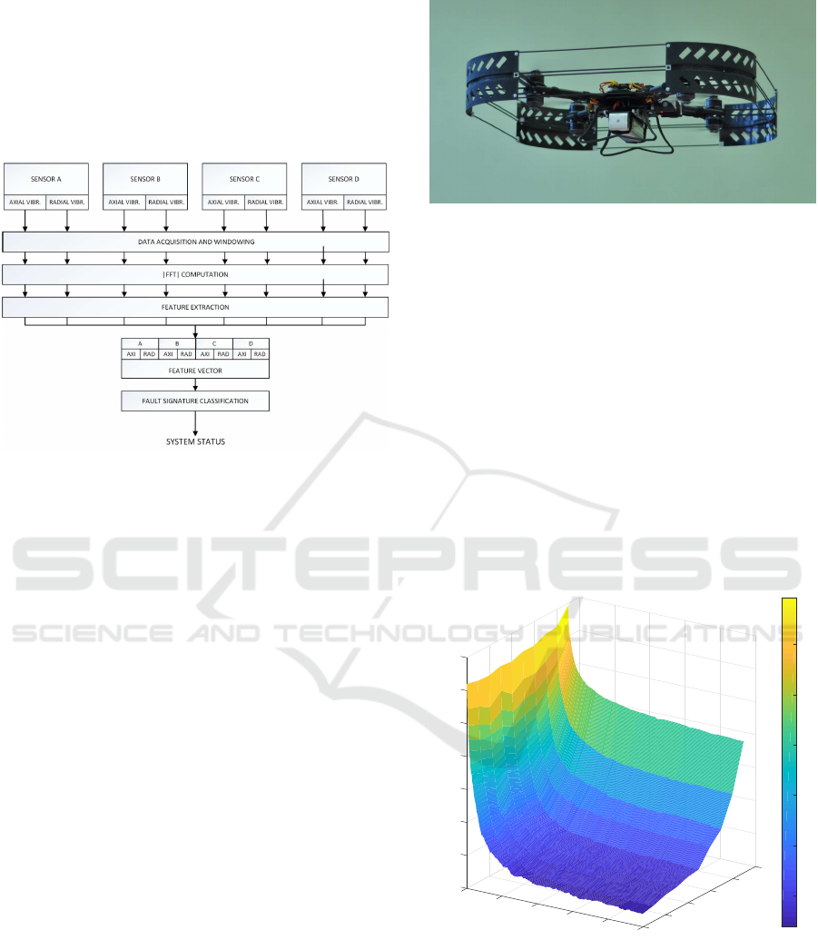
Figure 3: Hardware architecture of the developed FDI sys-
tem.
5 ANALYSIS OF VIBRATION
SIGNALS
Authors assumed that the main frequency of vibra-
tion signal will correspond to the angular velocity of
ICINCO 2018 - 15th International Conference on Informatics in Control, Automation and Robotics
104
the damaged propeller. Therefore, the initial signal
analysis focused on observing vibration spectra ob-
tained by the network of sensors. First experiments
were performed during steady hover flight, with the
angular velocity of rotors as constant as possible. A
Falcon V5 drone (Bondyra et al., 2015) was selected
for the test platform along with the embedded system
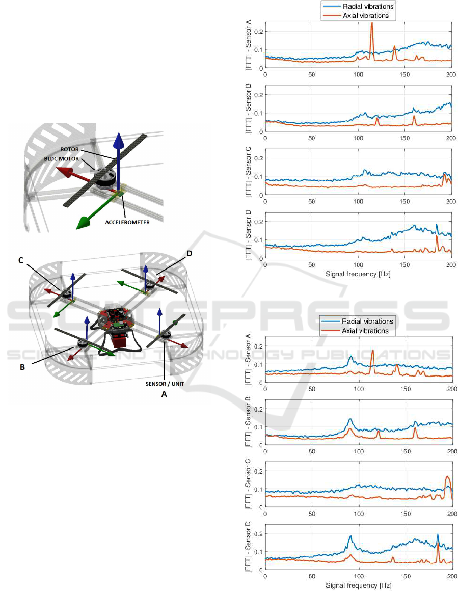
described in the previous section. Fig. 4 presents the
UAV partial CAD model along with sensors place-
ment and propulsion units’ notation.
Figure 4: The partial CAD model of the Falcon V5 UAV
with locations of vibration sensors.
The aim of this approach was to determine some
dependencies in the vibration signals which could be
used for the fault classification algorithm. Fig. 5
shows exemplary averaged spectra of radial and ax-
ial vibrations obtained during 10 seconds of the data
acquisition. In this case, all four rotors were undam-
aged.
Overview of recorded spectra shows a significant
amount of vibrations of the mechanical structure of
the UAV. However, no indicator of actuator faults can
be seen. In another scenario, the fault occurred at the
propulsion unit A with the angular velocity of pro-
pellers varying between 550-600 rad/s. Spectra of
recorded vibration signals are shown in the Fig. 6.
Measurements of radial vibrations show clearly
the faulty state with the characteristic vibration fre-
quency of about 90 Hz. However, the spectral peak
Figure 5: Averaged spectra of vibration signals recorded
with undamaged rotors.
Figure 6: Averaged spectra of vibration signals recorded
during the fault occurrence at the unit A.
Development of the Sensory Network for the Vibration-based Fault Detection and Isolation in the Multirotor UAV Propulsion System
105

can be observed with the highest amplitude at the sen-
sors B and D. The spectrum obtained with the sensor
placed closest to the faulty actuator (A) shows mod-
erate frequency peak, while the sensor C, located at
the opposite end of the UAV mechanical structure in-
dicates the dampening of the fault frequency. These
observations lead to the following conclusions: due
to the nature of the vibration propagation along the
airframe of the multirotor, the fault indicators are not
necessarily shown by the closest accelerometer. Ob-
servations from all of the sensors are required to de-
termine fault location. However, the spectral patterns
are clearly visible for the fault detection itself. On
the other hand, characteristic fault frequency varies
during the flight with regard to the angular velocity
of rotors. In addition, a variety of frequency compo-
nents from different vibration sources can be seen in
spectra. It leads to a conclusion, that simple fault fre-
quency detection methods are insufficient and a ma-
chine learning mechanism can be introduced.
6 FAULT DETECTION METHOD
An algorithm for the fault detection and localization
comprises three main stages:
6.1 Data Acquisition
The vibration signals are acquired thanks to the set
of MEMS sensory modules and the DAQ. Then, some
basic operations are performed on the raw signal vec-
tors: the normalization and windowing of the samples
using the Hanning window. The length of the sam-
pling window (T
w
) is a parameter affecting the per-
formance of the diagnostic method. Its impact is pre-
sented in the section 7.
6.2 Feature Extraction
For pre-processed signal vectors, the single-sided am-
plitude spectrum is computed using the Fast Fourier
Transform (FFT). Then, for 16 predefined frequency
ranges (frequency bins), the RMS of the spectrum
is computed. Calculated values create a vector of
features for single-axis, single-sensor measurements.
Frequency bins are linearly spaced and have an equal
width of 5Hz. However, lower and upper frequency
limits for the first and last bin are parameters to be
tuned. Since the fault frequency corresponds directly
to the angular velocity of UAV rotors, the spectrum
analysis window is narrowed to fit between 60 to 140
Hz. These frequencies resemble angular velocities
within the range of 370 to 880 rad/s, which are typ-
ical for most propulsion systems of micro multirotor
UAVs. The process of splitting the amplitude spec-
trum into frequency bins is summarized graphically
in the Fig. 7.
Figure 7: Principles of the feature extraction: single axis vi-
bration spectrum with corresponding set of calculated sig-
nal features.
With features extracted from the axial and ra-
dial measurements of every accelerometer, the feature
vector is formed. The data measured at the vertical
axis was omitted because further analysis has shown
the negligible significance of obtained features. A
complete vector of vibration features for quadrotor
consists of 128 elements with axial and radial features
of four propulsion units.
6.3 Fault Signature Classification
The final stage of signal processing pipeline is a fea-
ture classification. A set of random decision trees
(Breiman, 2001) was used for this task. In order to
detect and isolate actuator faults, a classifier processes
computed vector of features and assigns an adequate
class based on the trained vibration patterns. Its prin-
ciple of operation is based on aggregating many weak
classifier grouped in common ensemble (bag). A ran-
dom subset of predictors is chosen for each decision
split during the process of growing decision trees.
The classification is based on the majority vote be-
tween final outcomes.
The classifier adjusted for quad-rotor UAV is
trained to recognize 11 different classes: all-healthy
rotors state, single faults in each propulsion unit and
double simultaneous impairments for every possible
pair of rotors.
ICINCO 2018 - 15th International Conference on Informatics in Control, Automation and Robotics
106
During the experimental stage (see sec. 7), a wide
dataset was acquired, with more than 13000 indepen-
dent data samples. The acquired data was split ran-
domly into 70 % of training dataset while remaining
30% was used for a validation. A summary of the
fault detection and isolation process is presented in
the Fig. 8.
Figure 8: Data flow diagram of the fault detection and iso-
lation system.
7 PERFORMANCE EVALUATION
7.1 Experimental Setup
In order to gather the dataset and validate the perfor-
mance of developed fault detection and isolation sys-
tem, a series of test flights was performed. The Falcon
V5 drone in the quad-rotor configuration was used for
this task. During experiments, a variety of possible
actuator faults were tested. First few flights were exe-
cuted with all rotors in a brand-new condition. Other
tests were performed with damaged propellers: all
cases of single unit faults and some double rotor im-
pairments, with adjacent and opposite pairs of dam-
aged rotors. For every case, over 300 seconds of the
in-flight vibration data were recorded while the UAV
performed different flight maneuvers. Then, the ac-
quired dataset was post-processed in order to train the
classifier and validate the method. A complete FDI
system, consisting of vibration sensors, DAQ and data
processing unit was mounted on-board of the UAV.
Fig. 9 shows the Falcon V5 UAV during the flight.
7.2 Tuning the Classifier
The processing of the experimental results has shown
that two parameters are essential to determine the per-
formance of detecting the fault occurrence and loca-
Figure 9: Falcon V5 UAV used for the performance evalua-
tion of the FDI system.
tion. Since the time of the acquisition of axial and
radial vibration signals is variable, the longer is the
time window, the more information and higher signif-
icance of signal features can be obtained. In addition,
an increased number of decision trees in the ensem-
ble may provide a higher accuracy. An analysis was
performed on the basis of an out-of-bag (OOB) er-
ror estimate chosen as a parameter to determine the
accuracy of the classification. The OOB measure de-
livers the estimate of true classification errors based
on testing the examples excluded during the training
stage(Banfield et al., 2007). The dataset obtained dur-
ing the series of test flights was evaluated in relation
to the window length and number of decision trees.
Results of the experiment are shown in the Fig. 10.
0
100
0.1
0.2
200
0
0.3
0.4
Window length [ms]
0.5
OOB error rate [%]
50
0.6
300
0.7
No of grown trees
100
0.8
150
400
200
500
250
0.2
0.3
0.4
0.5
0.6
0.7
Figure 10: Performance evaluation of the classifier.
An initial performance evaluation lead to a con-
clusion, that vibration signals have to be acquired for
at least 0.2 seconds (T
W
= 200ms). This time period
is the most significant factor influencing the fault de-
tection time lasting since the occurrence of the im-
pairment to the final decision of the FDI system. A
number of decision trees required for the correct clas-
Development of the Sensory Network for the Vibration-based Fault Detection and Isolation in the Multirotor UAV Propulsion System
107

sification of fault signatures has a lesser impact since
bags of several hundreds trees are not computation-
ally demanding.
7.3 Experimental Results
After initial tuning of the classifier parameters, a win-
dow length of 300ms was chosen for the exemplary
performance evaluation. The complete ensemble of
random decision trees consisted of 200 instances. The
fault detection and isolation system was validated
with remaining 30 % of the dataset.
Figure 11: Results of the fault detection and isolation exper-
iment - confusion matrix for T
W
= 300ms and the ensemble
of 200 decision trees.
According to the Fig. 11, the FDI system has
proven very high accuracy in detecting the fault oc-
currence itself. In over 99% of cases, a healthy state
of rotors was properly identified. In addition, sin-
gle rotor impairments were detected correctly in over
93.9% of cases. However, faults in units A and C are
recognized in more cases. It may lead to a conclu-
sion that the proper placement of the sensors may af-
fect the performance of the fault detection since every
vibration sensor is mounted in the same relation and
distance to the propulsion unit. Double rotor damages
are harder to detect, but they are rarely mistaken for
the healthy state. In most cases of the wrong classifi-
cation, the localization of damaged units failed, while
the system indicated correctly that the dual fault oc-
curred. Especially the detection of two faulty adja-
cent actuators (the C-D pair) was harder to distinguish
from other fault classes.
7.4 Comparison of Results
Very few methods based on the signal processing
of airframe vibrations can be found in the litera-
ture. However, the performance of fault estimation
method was compared with some similar algorithms.
Sensitivity of presented method exceeds 95%, which
is similar to existing solutions (Jiang et al., 2015),
(Bondyra et al., 2017). Another performance factors,
such as rate of missed faults and false detection of
occurrence are comparable as well. However, these
methods lack the ability to isolate the fault and de-
liver its precise location, which is the main advantage
and novelty of presented approach.
8 CONCLUSIONS
Several advantages of the proposed solution can be
pointed out. The developed fault detection and iso-
lation system provides high detection rate. Fault oc-
currence is detected in more than 95 % of cases us-
ing quite a simple signal processing methods and not
computationally demanding classification method. In
case of single actuator faults, implementation of the
network of vibration sensors allows to isolate and lo-
calize fault precisely. Clear indicators of double ro-
tor damages are provided. However, these categories
of faults are easily mistaken in terms of isolating the
specific faulty rotor pair. In addition, utilizing an ex-
ternal, signal processing based system is a very ver-
satile solution and can be easily implemented in the
arbitrary multirotor UAV with the small cost.
On the other hand, in case of implementing the
external sensor network, additional equipment of the
UAV is required. Moreover, the response time of the
FDI system is dependent mostly on the time of signal
acquisition. Hence, there is some significant delay be-
tween fault occurrence and diagnostics information.
Application of the presented FDI system to the arbi-
trary multirotor requires a process of training of the
classifier. Further research will focus on tuning the
method, decreasing the required data acquisition time
and implementation of the fault detection system with
the corresponding fault-tolerant control scheme.
ACKNOWLEDGEMENTS
This research was funded by the Poznan University of
Technology grant DSPB/0162.
REFERENCES
Aszkowski, P., Błoszyk, K., Bondyra, A., Ga¸sior, P., and
Giernacki, W. (2017). UAV propulsion analysis sys-
tem with reconfigurable controller feature. Measure-
ment Automation Monitoring, 63(5):171–173.
ICINCO 2018 - 15th International Conference on Informatics in Control, Automation and Robotics
108

Banfield, R. E., Hall, L. O., Bowyer, K. W., and
Kegelmeyer, W. P. (2007). A comparison of deci-
sion tree ensemble creation techniques. IEEE Trans-
actions on Pattern Analysis and Machine Intelligence,
29(1):173–180.
Bondyra, A., Gardecki, S., Ga¸sior, P., and Kasi´nski, A.
(2015). Falcon: A compact multirotor flying plat-
form with high load capability. In Progress in Au-
tomation, Robotics and Measuring Techniques, pages
35–44. Springer.
Bondyra, A., Ga¸sior, P., Gardecki, S., and Kasi´nski, A.
(2017). Fault diagnosis and condition monitoring of
UAV rotor using signal processing. In 2017 Sig-
nal Processing: Algorithms, Architectures, Arrange-
ments, and Applications (SPA), pages 233–238.
Breiman, L. (2001). Random forests. Machine Learning,
45(1):5–32.
Clothier, R. A. and Walker, R. A. (2006). Determination
and evaluation of UAV safety objectives.
Fekih, A. (2014). Fault diagnosis and fault tolerant con-
trol design for aerospace systems: A bibliographical
review. In 2014 American Control Conference, pages
1286–1291.
Gardecki, S., Giernacki, W., Go´sli´nski, J., and Kasi´nski,
A. (2014). An adequate mathematical model of four-
rotor flying robot in the context of control simulations.
Journal of Automation Mobile Robotics and Intelli-
gent Systems, 8(2):9–17.
Gorospe, G. E. and Kulkarni, C. S. (2017). A novel UAV
electric propulsion testbed for diagnostics and prog-
nostics. In 2017 IEEE AUTOTESTCON.
Jiang, Y., Zhiyao, Z., Haoxiang, L., and Quan, Q. (2015).
Fault detection and identification for quadrotor based
on airframe vibration signals: A data-driven method.
In 2015 34th Chinese Control Conference (CCC),
pages 6356–6361.
Merheb, A. R., Noura, H., and Bateman, F. (2014). Active
fault tolerant control of quadrotor UAV using sliding
mode control. In 2014 International Conference on
Unmanned Aircraft Systems (ICUAS), pages 156–166.
Mohammed, F., Idries, A., Mohamed, N., Al-Jaroodi, J.,
and Jawhar, I. (2014). UAVs for smart cities: Oppor-
tunities and challenges. In 2014 International Confer-
ence on Unmanned Aircraft Systems (ICUAS), pages
267–273.
Nandi, S., Toliyat, H. A., and Li, X. (2005). Condition
monitoring and fault diagnosis of electrical motors-
a review. IEEE Transactions on Energy Conversion,
20(4):719–729.
Qi, X., ZhongKe, S., and HongYu, Z. (2013). Dual esti-
mation of attitude and parameters considering vibra-
tion based on gps and imu. In 2013 9th Asian Control
Conference (ASCC), pages 1–6.
Rago, C., Prasanth, R., Mehra, R. K., and Fortenbaugh,
R. (1998). Failure detection and identification and
fault tolerant control using the IMM-KF with appli-
cations to the eagle-eye UAV. In Proceedings of the
37th IEEE Conference on Decision and Control (Cat.
No.98CH36171), volume 4, pages 4208–4213 vol.4.
Valavanis, K. P. (2017). Unmanned aircraft systems chal-
lenges in design for autonomy. In 2017 11th Interna-
tional Workshop on Robot Motion and Control (Ro-
MoCo), pages 73–86.
Witczak, M. and Pazera, M. (2016). Fault tolerant-control:
Solutions and challenges. Pomiary Automatyka Robo-
tyka, 20(1):5–16.
Zhaohui, C. and Noura, H. (2013). A composite fault tol-
erant control based on fault estimation for quadro-
tor UAVs. In 2013 IEEE 8th Conference on In-
dustrial Electronics and Applications (ICIEA), pages
236–241.
Development of the Sensory Network for the Vibration-based Fault Detection and Isolation in the Multirotor UAV Propulsion System
109
