
Dynamics of Lateral Liquid Sloshing in Flat Cylinder Tanks
Zehong Wei
1
and Xuelian Zheng
2
1
School of automobile, Guangdong mechanical and electrical polytechnic, Guangzhou, China
2
School of Transportation, Jilin University, Changchun, China
weizehong@hust.edu.cn, zhengxuelian@jlu.edu.cn
Keywords: Liquid sloshing, cylinder tank, simulation, dynamics.
Abstract: As a complicated fluid-solid coupling multi-body system, the modelling of tankers are quite difficult. Many
efforts had been made to establish equivalent mechanical model to describe liquid sloshing in tanker to
simplify the modelling of tankers. The investigation on dynamics of liquid sloshing in tanks will be of great
significance and a necessary support. FLUENT software was used to simulate liquid sloshing in flat
cylinder tank under the situation of different lateral acceleration and liquid fill level, the center of mass
(CM) of liquid bulk was utilized to analyze the dynamics of liquid sloshing. It turned out that the trajectory
of liquid bulk’s CM could be described by a curve, not the whole liquid bulk participates in sloshing, and
there is a strong nonlinear characteristics in sloshing damping.
1 INTRODUCTION
Road tank vehicles are commonly used in carrying a
wide range of liquid cargoes, mainly of a dangerous
nature. At the same time, tankers also create severe
traffic safety problems, which would result in huge
people injury and property damage. Therefore, great
attention must be paid to tanker driving safety.
It was universally accepted that liquid sloshing in
partially-filled tanks is the most important factor
result in tanker traffic accidents (Hasheminejad et al,
2009). As a complicated fluid-solid coupling multi-
body system, it is quite hard to model tank vehicles,
not even to investigate tankers’ dynamic
characteristics (Rumold, 2001). On the assumption
of an equivalent mechanical model was established
to describe liquid sloshing in tanks, the modelling of
tanker and its dynamic analysis will be an easy work
(Salem, 2000; Zheng et al, 2012; Qing et al, 2011;
Utsumi, 2004). Hence, the purpose of this paper is to
investigate dynamics of liquid sloshing in flat
cylinder tank which are widely used in tankers. The
research result will be a support for the
establishment of equivalent mechanical model.
2 FLUENT SIMULATION FOR
LATERAL LIQUID SLOSHING IN
FLAT CYLINDER TANKS
The software of FLUENT was used to simulate
lateral liquid sloshing in flat cylinder tanks. By
FLUENT simulation, lateral sloshing force acting on
tank walls, liquid bulk’s transient CM, and sloshing
moment on specific point were recorded. Also,
sloshing animation was generated to judge
subjectively whether software simulation could
reproduce lateral liquid sloshing correctly or not.
2.1 Tank model
A flat cylinder tank model with a length of 1 m and
a radius of 0.86 m was used in this study. The radius
of this tank model was decided according to market
survey on cross-sectional area of tanks on tank
vehicles. It was showed that the value was about 2.5
m
2
. The length of this tank model was set given the
consideration of calculation simplicity of the mass of
liquid bulk.
Only lateral liquid sloshing was taken into
account in the flat cylinder tank, and liquid sloshing
in different cross sections were supposed to be the
same. Therefore, the three dimensional liquid
sloshing in cylinder tank could be substituted for
two dimensional sloshing in tank cross sections.
308
Wei, Z. and Zheng, X.
Dynamics of Lateral Liquid Sloshing in Flat Cylinder Tanks.
In 3rd International Conference on Electromechanical Control Technology and Transportation (ICECTT 2018), pages 308-313
ISBN: 978-989-758-312-4
Copyright © 2018 by SCITEPRESS – Science and Technology Publications, Lda. All rights reserved

A pressure inlet was set on the top of tank cross
section. The circular cross section model was
meshed with elements of quadrangle, and pave was
selected as the meshing type.
2.2 Sloshing condition
Liquid fill percentage was used to describe the
volume or the mass of liquid bulk in the tank. It was
defined as the ratio of the height of liquid free
surface to the diameter of the tank. Lateral liquid
sloshing under the condition of different liquid fill
levels was considered, and the liquid fill level was
set to be 0.1, 0.2, 0.3, 0.4, 0.5, 0.6, 0.7, 0.8, 0.9,
respectively.
In practical situation, lateral acceleration of tank
vehicles is hardly to exceed 1.0 g. therefore, lateral
acceleration acts on tank was set to be 0.1 g, 0.2 g,
0.3 g, 0.4 g, 0.5 g, 0.6 g, 0.7 g, 0.8 g, 0.9 g and 1.0 g,
respectively.
The purpose of this study was to investigate
inherent dynamics of liquid sloshing and to establish
equivalent mechanical model. There hence, free
oscillation of liquid bulk should be simulated to
acquire sloshing parameters. To simulate free
oscillation of liquid bulk, liquid bulk’s CM should
be away from equilibrium position. Two different
methods to obtain the initial condition of free
oscillation were proposed. For the first one, forced
oscillation under the action of lateral acceleration
was carried out first. While the center of mass of
liquid bulk arrives at the highest point, the
simulation of forced oscillation was stopped. Then,
the ended moment in this forced oscillation case was
taken as the initial condition of free liquid sloshing.
For the second one, liquid free surface was set to be
tilted at the very beginning of free oscillation
simulation. Gradient of tilted liquid free surface was
obtained by
()
0
=atan
y
ag
θ
(1)
where a
y
is lateral acceleration acting on tanks.
While the second method to simulate liquid free
oscillation was much easier than the first one, it was
used to simulate liquid sloshing in this study.
2.3 Simulation settings
A 2D planer, transient simulation was used to
simulate liquid sloshing in flat cylinder tank.
Pressure-based was selected as the solver. Air and
water were multiphase flows in tank model, and air
was set to be the primary phase. The volume of
water, and intersection line between air and water
were defined by user defined function. Laminar was
used as the viscous model. Pressure inlet was set on
the top of circular cross section, and the pressure
inlet was also set to be reference pressure location.
Gravity was acted on the liquid bulk, who directs to
the negative y-axis. The scheme of PISO was used
as pressure-velocity coupling method. For other
parameters, they were accepted as software default
setting.
Sloshing force and moment were monitored
during simulation. Liquid bulk’s CM was calculated
and recorded by user defined function.
3 DATA FILTERING BY
WAVELET
Liquid bulk’s CM was used to investigate sloshing
dynamics in this study. Before dynamic analysis,
data filtering was carried out. Many filtering
methods were tried, it turned out that wavelet
filtering has the best performance. Therefore, liquid
bulk’s CM, including x-coordinate and y-coordinate,
was filtered by wavelet. Sym8 was chosen as the
wavelet function, and 8 layer decomposition was
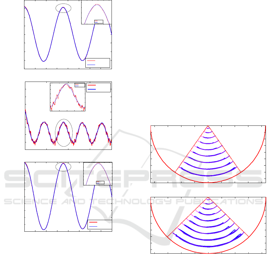
done. Comparison of liquid bulk’s CM before and
after wavelet filtering was presented in Figure 1.
Also, oscillation angle of liquid bulk’s CM, which
was a function of x-coordinate and y-coordinate, was
also presented to illustrate data filtering result.
In Figure 1, oscillation angle was obtained by
()
=atan
x
y
θ
−
(2)
where x is the x-coordinate of liquid bulk’s CM, y is
the y-coordinate of liquid bulk’s CM.
Noise in raw data was with small amplitude and
did have regular frequencies. Reason that bring
irregular noise should be calculation accuracy error.
For this situation, wavelet filtering was a pleasure
select.
Compared with x-coordinate, y-coordinate has
noise with rather large amplitude. That is to say that
y-coordinate of liquid bulk’s CM has much violent
changes in sloshing, and the change trend along y-
axis has much lower possibility than that along x-
axis.
Oscillation angle obtained by filtered liquid
bulk’s CM is much smoother that that obtained by
raw data, which reveals the correctness of data
filtering.
Dynamics of Lateral Liquid Sloshing in Flat Cylinder Tanks
309
0 0.5 1 1.5 2 2.5 3 3.5 4
-0.08
-0.06
-0.04
-0.02
0
0.02
0.04
0.06
0.08
time,s
x-coordinate of CG,m
unfiltered
filtered
1.5 1.6 1.7 1.8 1.9 2
0.045
0.05
0.055
0.06
0.065
time,s
x-coordinate of CG,m
unfilte red
filtered
0 1 2 3 4
-0.658
-0.657
-0.656
-0.655
-0.654
-0.653
-0.652
-0.651
-0.65
-0.649
time,s
y-coordinate of CG,m
unfiltered
filtered
1.4 1.6 1.8 2 2.2
-0.657
-0.6565
-0.656
-0.6555
-0.655
-0.6545
time, s
y-coordinate of CG,m
unfilt ered
filtered
0 0.5 1 1.5 2 2.5 3 3.5
4
-0.1
-0.08
-0.06
-0.04
-0.02
0
0.02
0.04
0.06
0.08
0.1
time,s
oscillation angle,rad
unfiltered
filtered
1.5 1.6 1.7 1.8 1.9 2
0.065
0.07
0.075
0.08
0.085
0.09
0.095
time, s
oscillation angle,rad
unfiltered
filtered
Figure 1: Comparison of liquid bulk’s CM before and after
wavelet filtering.
4 DYNAMICS OF LATERAL
LIQUID SLOSHING
Dynamics of lateral liquid sloshing was investigated
by filtered liquid bulk’s CM. Its moving trajectory,
oscillation frequency and damping were researched
in this study.
4.1 Trajectory of the center of mass of
liquid bulk
Trajectory of the center of mass of liquid bulk under
different lateral accelerations, i.e. different tilted
liquid free surface, were presented in Figure 2 as
blue lines. Also, circle which has the radius that is
equal to the mean value of distances from liquid
bulk’s transient CM to the center of tank cross
section was also presented as pink line. The tank
was expressed by red line. The maximum oscillation
angle of liquid bulk’s CM, which was defined by the
tilt angle of liquid free surface at the very beginning,
was expressed by dotted red line.
For each tilted liquid free surface, liquid fill
percentage changes from 0.1 to 0.9. FP is short for
liquid fill percentage, and LA is short for lateral
acceleration in Figure 2.
-0.8 -0.6 -0.4 -0.2 0 0.2 0.4 0.6 0.8
-0.8
-0.7
-0.6
-0.5
-0.4
-0.3
-0.2
-0.1
0
x-coordinate,m
y-coordinate,m
FP0.1-LA0.7
FP0.2-LA0.7
FP0.3-LA0.7
FP0.4-LA0.7
FP0.5-LA0.7
FP0.6-LA0.7
FP0.7-LA0.7
FP0.8-LA0.7
FP0.9-LA0.7
(1) lateral acceleration is 0.7 g
-0.8 -0.6 -0.4 -0.2 0 0.2 0.4 0.6 0.8
-0.8
-0.7
-0.6
-0.5
-0.4
-0.3
-0.2
-0.1
0
x-coordinate
,
m
y-coordinate,m
FP0.1-LA1.0
FP0.2-LA1.0
FP0.3-LA1.0
FP0.4-LA1.0
FP0.5-LA1.0
FP0.6-LA1.0
FP0.7-LA1.0
FP0.8-LA1.0
FP0.9-LA1.0
(2) lateral acceleration is 1.0 g
Figure 2: Trajectory of liuqid bulk’s CM under different
lateral acceleration and fill percentage
It was quite clear that the trajectory of liquid
bulk’s CM coincides well with the specific circle. A
much more detailed investigation showed that R-
square between the two lines is 1.00 for most cases,
only case of FP=0.1, LA=1.0 g and FP=0.2, LA=1.0
g is 0.99. This result revealed that the trajectory of
liquid bulk’s CM could be described by a circle, and
radius of this circle is the mean value of distances
from liquid bulk’s transient CM to the center of tank
cross section.
ICECTT 2018 - 3rd International Conference on Electromechanical Control Technology and Transportation
310
4.2 The part of liquid bulk participates
in sloshing
An interesting phenomenon was discovered from
curves of oscillation angle of liquid bulk’s CM
which can be obtained by equation (2), as shown in
Figure 3. It was quite clear that liquid sloshing is a
damped oscillation, whose amplitude decreases as
time goes on. Differences in amplitude between
peaks were smooth and small, however, the
difference between original oscillation angle and
amplitude of the first peak are quite large, and the
difference does not keep constant under different
simulation conditions. It seems like that after liquid
bulk sloshes under the action of gravity, its CM
drops greatly and it could not arrive at its original
position.
0 5 10 15 20
-0.3
-0.2
-0.1
0
0.1
0.2
0.3
0.4
0.5
0.6
Time,s
Theta,rad
Figure 3: Curves for oscillation angle of liquid bulk’s CM
when LA=0.6,FP=0.9
A ratio was defined to describe the difference
between the original oscillation angle of liquid
bulk’s CM and amplitude of the first peak, which is
expressed by
10P
ra
θθ
=
(3)
where
1
P
θ
is amplitude of the first peak.
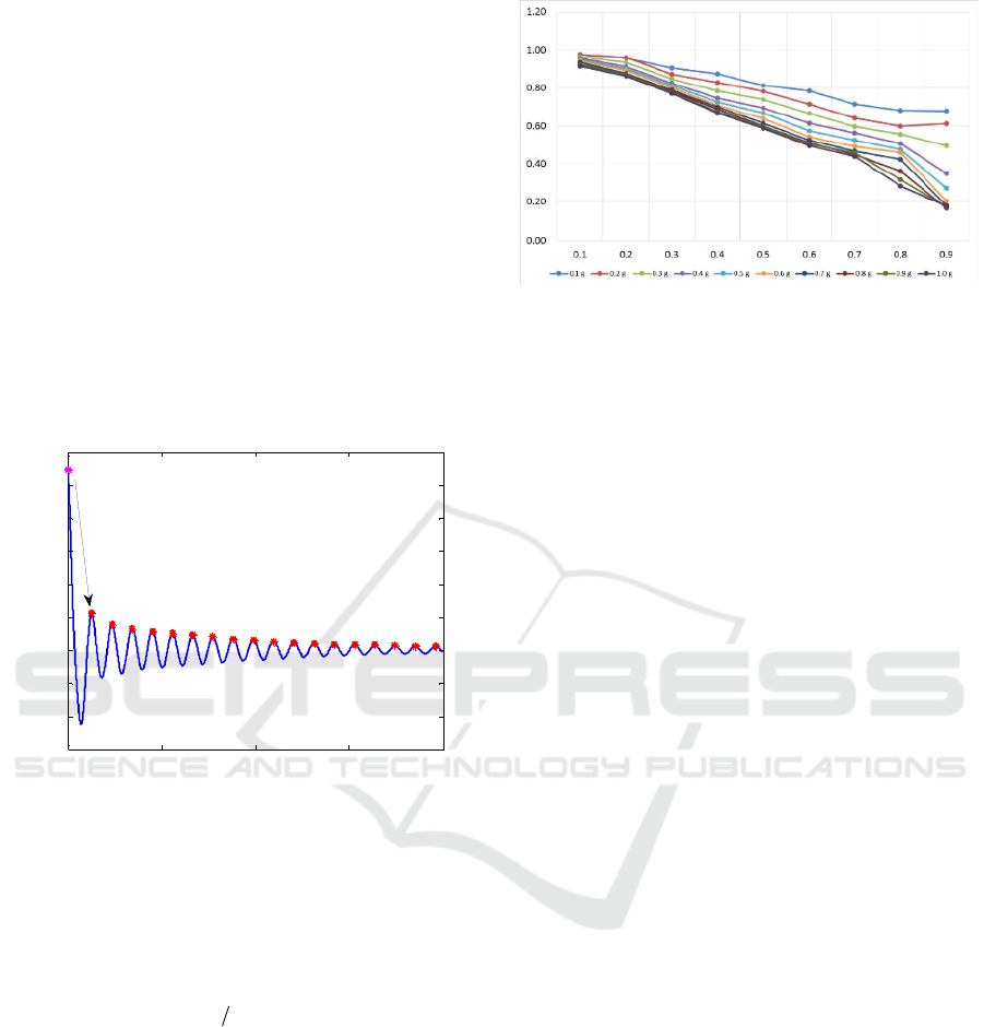
For all simulation conditions, ra was calculated
and presented in Figure 4. While lateral acceleration
keeps constant, ra decreases with the increasement
of liquid fill level. Besides, while liquid fill
percentage keeps constant, ra decreases with the
increasement of lateral acceleration. The ratio
changes from 0.98-0.17.
Figure 4: ra in different simulation conditions
The great drop from original oscillation angle
was supposed not be caused by damping, due to the
fact that damping coefficient obtained by the ratio is
too large. A possibility reason lead to this
phenomenon is the fact that not the whole liquid
bulk participates in sloshing. For simulation initial
condition, liquid bulk’s CM was set to away from
equilibrium position. Its coordinate was determined
by gradient of liquid free surface, tank shape, and
liquid fill level. As the simulation starts, liquid
bulk’s CM moves towards the equilibrium position,
and it will arrives at a highest position under the
action of inertial force. However, due to the fact that
not the whole liquid bulk participates in sloshing,
liquid bulk’s CM cannot arrives at its original
position, or even arrives at a position that is close to
its original position. After the first peak, liquid bulk
oscillates under the action of inertial force, and its
amplitude decreases gradually because of damping.
It was also drawn from Figure 4 that the part of
liquid that participates in sloshing decreases with the
increasement of lateral acceleration and liquid fill
level.
4.3 Liquid sloshing frequency and
damping
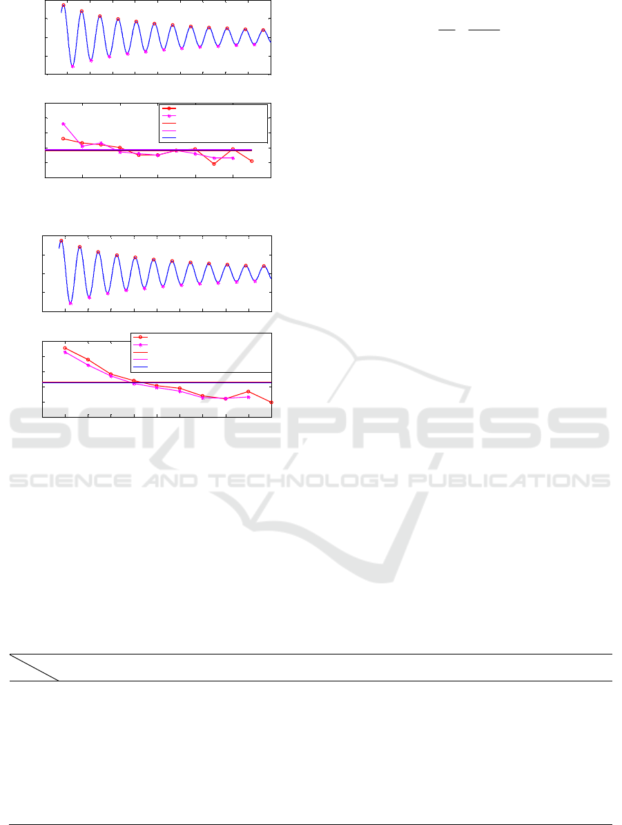
Sloshing frequency and damping were studied
according to curves of oscillation angle. As shown in
Figure 5 and Figure 6. Peaks and valleys of
oscillation angle were picked out, and oscillation
period can be obtained by time interval between
adjacent peaks or valleys. Periods obtained by peaks
and those obtained by valleys have little difference,
their mean values are almost the same.
Dynamics of Lateral Liquid Sloshing in Flat Cylinder Tanks
311
0 2 4 6 8 10 12 14 16 18 20
-0.4
-0.2
0
0.2
0.4
Time,s
Theta
0 2 4 6 8 10 12
1.59
1.6
1.61
1.62
1.63
1.64
Number
Time,s
period obtained by peaks
period obtained by valleys
average period obtained by peaks
average period obtained by valleys
average period
Figure 5: Sloshing frequency when FP=0.5, LA=0.6 g
0 2 4 6 8 10 12 14 16 18 20
-0.4
-0.2
0
0.2
0.4
Time,s
Theta
0 1 2 3 4 5 6 7 8 9 10
0.04
0.06
0.08
0.1
0.12
0.14
Number
Damping Coefficient
damping coefficient obtained by peaks
damping coefficient obtained by valleys
average damping coefficient obtained by peaks
average damping coefficient obtained by peaks
average damping coefficient
Figure 6: Sloshing damping when FP=0.5, LA=0.6 g
Besides, there is not an apparent changing trend
in period with time grows. Therefore, the mean
value of periods obtained by peaks and those
obtained by valleys is supposed to be sloshing
period. Based on that, sloshing frequency in
different simulation conditions were acquired, which
were listed in Table 1.
Damping coefficient can also be obtained by
adjacent peaks or valleys, which is expressed by
()
1
=ln
p
i
p
in
nT
θ
β
θ
+
(4)
where T is oscillation period,
p
i
θ
is amplitude of the
ith peak or valley,
()
p
in
θ
+
is amplitude of the (i+n)th
peak or valley. Damping coefficients obtained by
peaks or valleys have quite little difference.
However, damping coefficient drops with time flies,
which means that damping characteristics of lateral
liquid sloshing is nonlinear. Furthermore, the
changing trend of damping coefficient is quite
apparent, which cannot be ignored.
The mean value of damping coefficients obtained
by peaks and valleys were also calculated, which
were listed in Table 2.
5 CONCLUSIONS
Lateral liquid sloshing in flat cylinder tanks under
the situation of different lateral acceleration and
cargo fill percentage were simulated by FLUENT.
The center of mass of liquid bulk were used to
investigate dynamics of lateral liquid sloshing, it
was discovered that:
(1) The trajectory of liquid bulk’s CM could be
described by a curve.
(2) Not the whole liquid bulk participates in
sloshing.
(3) Sloshing frequency almost keeps constant,
but its damping coefficient drops gradually with
time goes on.
Based on the dynamics of liquid sloshing,
equivalent mechanical model can be established.
This will be the future work. Furthermore, dynamics
of lateral sloshing for other kinds of liquid should be
investigated to get much more universe conclusions.
Table 1: Frequency of lateral liquid sloshing
LA
FP
0.1g 0.2g 0.3g 0.4g 0.5g 0.6g 0.7g 0.8g 0.9g 1.0 g
0.1 1.8232 1.8247 1.8292 1.8341 1.8397 1.8459 1.8522 1.8581 1.8646 1.8685
0.2 1.7777 1.7825 1.7853 1.7885 1.7918 1.7962 1.8013 1.8087 1.8141 1.8192
0.3 1.7274 1.7322 1.7335 1.7364 1.7391 1.7418 1.7444 1.7471 1.7503 1.7530
0.4 1.6702 1.6725 1.6747 1.6758 1.6774 1.6789 1.6808 1.6823 1.6838 1.6856
0.5 1.5999 1.6038 1.6052 1.6051 1.6095 1.6083 1.6089 1.6095 1.6100 1.6114
0.6 1.5193 1.5200 1.5208 1.5223 1.5234 1.5256 1.5259 1.5255 1.5264 1.5270
0.7 1.4174 1.4190 1.4200 1.4238 1.4207 1.4212 1.4221 1.4227 1.4224 1.4205
0.8 1.2800 1.2823 1.2840 1.2824 1.2831 1.2840 1.2833 1.2836 1.2850 1.2836
0.9 1.0730 1.0768 1.0750 1.0781 1.0783 1.0802 1.0825 1.0821 1.0826 1.0830
ICECTT 2018 - 3rd International Conference on Electromechanical Control Technology and Transportation
312

Table 2: Damping of lateral liquid sloshing (10
-2
)
LA
FP
0.1g 0.2g 0.3g 0.4g 0.5g 0.6g 0.7g 0.8g 0.9g 1.0 g
0.1 0.69 0.80 0.95 1.14 1.35 1.54 1.71 1.85 1.99 2.10
0.2 0.56 1.62 2.03 2.34 2.83 3.06 3.33 3.43 3.55 3.65
0.3 1.79 3.51 3.65 4.55 5.01 5.31 5.54 5.80 6.21 5.98
0.4 2.25 4.30 5.63 6.01 6.79 7.02 7.47 7.52 7.94 8.29
0.5 2.73 5.26 7.12 7.17 9.53 8.45 8.82 8.98 8.63 9.05
0.6 4.28 8.02 9.35 10.70 11.31 11.57 11.82 11.30 11.24 11.34
0.7 5.39 9.81 11.43 12.10 11.95 11.93 12.69 13.24 13.05 12.47
0.8 5.74 10.26 11.70 11.92 11.79 13.01 12.81 13.11 13.58 12.75
0.9 4.81 9.73 10.69 11.32 12.16 12.04 12.46 13.06 12.96 11.58
REFERENCES
Hasheminejad, SM&Aghabeigi, M2009. Liquid
sloshing in half-full horizontal elliptical tanks.
Journal of Sound and Vibration, 324(1-2): 332-
349.
Qing, L& Xingrui, M 2011. Equivalent mechanical
model for liquid sloshing during draining. Acta
Astronautica, 68: 91-100.
Rumold, W2001. Modeling and simulation of
vehicle carrying liquid cargo. Multi-body System
Dynamics, 5(04): 351-374.
Salem MI 2000. Rollover stability of partially filled
heavy-duty elliptical tankers using trammel
pendulums to simulate fluid sloshing. PhD
thesis, West Virginia University, Department of
Mechanical and Aerospace Engineering.
Utsumi, M, 2004. A mechanical model for low-
gravity sloshing in an axisymmetric tank.
Transactions of the ASME, 71: 724-730.
Zheng XL & Li XS 2012. Equivalent mechanical
model for lateral liquid sloshing in partially-
filled tank vehicles. Mathematical Problems in
Engineering, ID: 162825.
Dynamics of Lateral Liquid Sloshing in Flat Cylinder Tanks
313
