
Numerical Calculation for Asynchronous Magnetic Coupling
Kaikai Zhou
1
, Peng Wang
1
, Zhi Yuan
1
and Yanjun Ge
1
1
College of Mechanical Engineering, Dalian Jiaotong University, Huanghe Street, Shahekou Distict, China
Keywords: Asynchronous magnetic coupling, Mechanical properties, Magnetic field analysis, Vector magnetic
potential
Abstract: The available magnetic circuit algorithm is difficult to calculate exactly the electromagnetic torque of the
asynchronous magnetic coupling (AMC). The present study establishes the gap flux density theory model
by the use of vector magnetic potential method and the two-dimensional field boundary condition, and then
analyzes the variation law of induction current among the cage bars along with the spatial phase and electric
angle. The Lorenz force is integrated around the circumferential direction, and then the electromagnetic
torque model was established according to the current superposition principle. The obtained theoretical gap
flux density, cage bars induced current and torque were analyzed comparatively with the finite element
method. The revolving speed curve, torque curve and current curve of AMC under rated condition were
obtained by the method of finite element dynamic analysis, and then the electromagnetic torque
characteristic curve was draw to reveal its dynamic operation law. At last, the correctness of the mechanical
characteristics of AMC was verified by experimental results.
1 INTRODUCTION
In recent years, adjustable-speed magnetic couplings
have been very successfully introduced to provide a
high-efficiency alternative means of control by
matching the motor output speed and torque to the
requirements of the load[1, 2]. Compared with the
ordinary couplings, magnetic coupling has the
advantages of non-contact power transmission, no
friction, stable transmission, low working condition,
low maintenance cost, etc. Compared with variable-
frequency drives (VFD)[3], magnetic coupling do
not generated electronic harmonics which will cause
system problems and may overheat motor windings.
The squirrel cage rotor has been tested for a long
time, and the theory is relatively mature. Therefore,
the use of standard squirrel cage rotor design
magnetic coupling has the advantages of low design
cost, easy to manufacture, and can be applied to the
field of electromagnetic braking, and has attracted
widespread attention of scholars. The Flux Drive
company in the United States has commercial
production of speed adjustable squirrel cage rotor
couplings, but its cage rotor needs to be redesigned
and has a longer design cycle, and there is no
literature to report its mechanical properties[4]. To
solve this problem, an asynchronous magnetic
coupling based on an existing squirrel cage rotor is
proposed[5,6].
The mechanical analysis of magnetic drive
mainly includes analytic method[7,8] and finite
element method[9,10]. In this paper, the two
methods are combined to do the following research
work: the gap flux density theory model is
established by the use of vector magnetic potential
method, and then the variation law of induction
current among the cage bars along with the spatial
phase and electric angle are analyzed. The torque is
analyzed by Faraday law of electromagnetic
induction. The obtained theoretical gap flux density,
cage bars induced current and torque are analyzed
comparatively with the finite element method.
2 STRUCTURE OF AMC
The asynchronous magnetic coupling is mainly
composed of the outer rotor, the squirrel cage rotor
and the air gap. The structure of the asynchronous
magnetic coupling is shown in Fig.1.

1. Permanent magnet 2. Cage bar 3. Yoke 4. Fill block(
Non-magnetic material) 5. Air gap 6. Cage rotor
Figure 1: The structure of the asynchronous magnetic
coupling.
3 TORQUE CALCULATION
The air gap magnetic field plays a decisive role in
the torque transmission of the asynchronous
magnetic coupling. Paper [1] has calculated the
radial component B
r
and the tangential component
B
θ
of the air gap magnetic field by using the vector
magnetic potential method. The formula is as
follows:
()
()
11
111
1
,cos()
np np
rnn
n
B r np A r B r np
θθ
∞
−−−
=
=+
∑
(1)
()
()
()
11
111
1
,sin
np np
nn
n
B r np A r B r np
θ
θθ
∞
−−−
=
=− −
∑
(2)
Where p is the pole-pairs of permanent magnet, r
is the air gap radius, A
n1
and B
n1
are constants for
calculation, the formula is as follows:
()()
()()
()()
()()
()
1
22 11
2332
2
01
1122
3223
2222
1223
2
11
23
2222
231 2
1
n
np np np np
np
n
np np np np
np np np np
r
np np
np np np np
A
RRRR
MR
npRRRR
RRRR
RR np
RRRR
μ
μ
−− −−
−
−−−−
−−−−
−−
−−−−
=
⎡⎤
+−
⎢⎥
⎢⎥
+− −
⎣⎦
⎡⎤
−+
⎡⎤
⎢⎥
−
⎣⎦
⎢⎥
+− +
⎣⎦
(3)
()()
()()
()()
()()
()
1
22 11
2332
0
112 2
3223
2222
1223
2
11
23
2222
231 2
1
n
np np np np
n
np np np np
np np np np
r
np np
np np np np
B
RRRR
M
npR R R R
RRRR
RR np
RRRR
μ
μ
−− −−
−−−−
−−−−
−−
−−−−
=
⎡⎤
+−
⎢⎥
⎢⎥
+− −
⎣⎦
⎡⎤
−+
⎡⎤
⎢⎥
−
⎣⎦
⎢⎥
+− +
⎣⎦
(4)
Where
μ
0
is the vacuum permeability, and the M
n
is the coefficients of the Fourier series expansions
(n=1, 2...), R
1
is the outer diameter of the squirrel
cage rotor, R
2
is the inner diameter of the permanent
magnet, and R
3
is the outer diameter of the
permanent magnet.
The induction electromotive force in each cage
bar of the squirrel cage rotor is proportional to the
magnetic field density, and the current direction can
be determined by the right-hand rule.
According to Faraday's electromagnetic
induction theorem, the maximum induction potential
induced by cutting magnetic induction lines in each
cage is as follows:
maxsr
EBLv= (5)
Where v is the relative rotation speed of internal
and external rotor, and
() ()
22
60 2 60
zl zl
Dn n pn n
D
vf
p
π
π
τ
−−
==⋅=
(6)
Because the squirrel cage rotor winding is self-
closing and the loop is formed, the terminal voltage
is in short-circuit state, and its terminal voltage is
zero. Each loop is routed by two cage bars, so that
the total potential in the circuit E
N
=2E
S
. According
to Kirchhoff's second law, the voltage balance
equation in the rotor winding is as follows:
20
ss
EIZ
σ
••
−= (7)
2
2
s
sB
E
sE
I
Z
RjsX
σσ
•
•
•
==
+
(8)
The effective value of the rated current is as
following:
22
2
()
B
sE
I
RsX
σ
=
+
(9)
The expression for the electromagnetic torque
can be expressed as follows:
0
22
00
22
1
22
0
22
4
()
15 ( )
Z
zw
i
B
zw
B
fwk
TTsZBL
pR sX
nwk
sZ B L
RsX
δ
σ
δ
σ
π
π
=
==
+
=
+
∑
(10)
4 FINITE ELEMENT ANALYSIS
The model parameters are shown in Table 1.
2-Dimension model is established according to
Tab.1 model parameters. Defining material attribute:
the materials of air gap, outer rotor, inner rotor and
permanent magnets should be defined when
analyzing the asynchronous magnetic coupling. The
model is divided into meshes, the result is shown in
Fig.2.
Table 1: Model parameters of SCRMC.
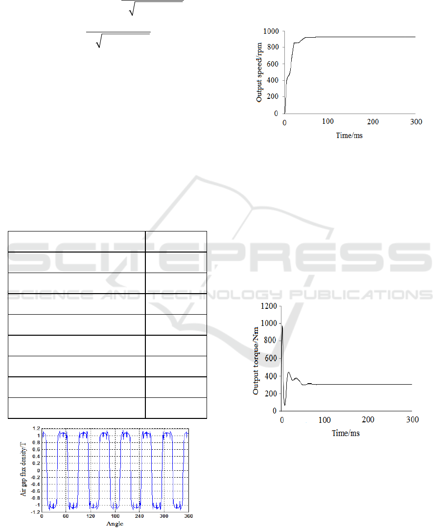
Figure 2: Radial air gap flux density diagram.
The remanence of the permanent magnet
material is 1.18T. In Fig.1, the average value of the
air gap magnetic density is about 1.1T, and the air
gap magnetic density distribution fluctuates slightly.
The minimum value is 0.9T, and the maximum
value is 1.18T, which indicates that there is leakage.
Figure 3: Speed diagram for AMC.
Using the dynamic analysis model, adding
motion conditions of outer rotor and an inner rotor,
and the setting conditions are as follows: outer rotor
speed is set to 1000 rpm, the initial rotational speed
of the inner rotor is set to 0 rpm, the moment of
inertia is 0.094 kgm2, the output power is 30 kW,
the solution time is 0.3 s, the step is set to 0.0004 s.
After the solution and the post-processing, the
results are obtained respectively, as shown in Fig.3
and Fig.4.
Figure 4: Torque diagram for AMC.
In order to further study the mechanical
characteristics of AMC, external rotor speed is fixed
as 1000 rpm and only the squirrel cage rotor speed is
changed, the cage rotor inertia, damping and other
mechanical properties are not considered. The final
mechanical characteristics of AMC are shown in
Fig.5.
Name
numerical
value
Pole pair of permanent magnet 7
The outer diameter of the yoke
/mm
120
The outer diameter of the
p
ermanent ma
g
net /mm
100
The inner diameter of the
p
ermanent ma
g
net /mm
90
The outer diameter of squirrel-cage
roto
r
/m
m
89.35
The inner diameter of squirrel-cage
roto
r
/m
m
30
Air gap /mm 0.65
Axial length /mm 85

Figure5: Mechanical characteristic diagram.
As shown in Figure 5: the mechanical properties
of AMC and three-phase asynchronous motor are
similar, slip ratio and torque are on a linear
relationship above the maximum torque, and on a
nonlinear relationship between the maximum torque
and maximum starting torque; the maximum torque0
Tm is 502.9 Nm, the corresponding slip is 0.18. The
maximum torque is greater than the rated torque,
which means that the AMC has overload ability. The
maximum starting torque is 306.8 Nm, and the load
torque from the start to the steady-state is less than
the corresponding torque from the motor mechanical
characteristic curve, which in accordance with the
design requirements of the working conditions.
5 CONCLUSIONS
In this paper, the static air gap magnetic field is
analyzed by ANSYS software, in good agreement
with the analytical method. The mechanical
performance of the squirrel cage rotor magnetic
coupling is analyzed from the start to the steady state
when the actual load is simulated by dynamic
analysis. When running stably, the output torque is
923.5 rpm and the output torque is 385.3 Nm; its
mechanical characteristic curve is also given.
ACKNOWLEDGEMENTS
This work is supported by Project of National
Natural Science Foundation of China (No.
51285092), all support is gratefully acknowledged.
REFERENCES
1. Fujun H E, Zhong Y, Zhang R, et al. Research on
Characteristics of Permanent Magnet Eddy-current
Coupling Drive[J]. Journal of Mechanical Engineering,
2016.
2. Li K, Bird J Z, Acharya V M. Ideal Radial Permanent
Magnet Coupling Torque Density Analysis[J]. IEEE
Transactions on Magnetics, 2017, PP(99):1-1.
3. Cuzner R, Drews D, Kranz W, et al. Power-Dense
Shipboard-Compatible Low-Horsepower Variable-
Frequency Drives[J]. IEEE Transactions on Industry
Applications, 2013, 48(6):2121-2128.
4. http://www.fluxdrive.com
5. Yanjun G E, Zhang S, Jiang Y, et al. Analysis and
calculation of the torque characteristics of squirrel
cage asynchronous magnetic coupling[J]. Modern
Machinery, 2015.
6. Zhou K, Yuan Z, Wang P, et al. Numerical calculation
for axial force of Adjustable Speed Asynchronous
Magnetic Coupling[C]// Progress in Electromagnetic
Research Symposium. 2016:1487-1491.
7. Y. J. Ge,C. Y. Nie,Q. Xin.A three dimensional
analytical of the air-gap magnetic field and torque of
coaxial magnetic gears.Progress In Electromagnetics
Research,2012, 131:391-407.
8. Anglada J R, Sharkh S M. Analytical calculation of
air-gap magnetic field distribution in transverse-flux
machines[C]// IEEE International Symposium on
Industrial Electronics. IEEE, 2016.
9. Yang C J, Li Q W, Ma H L, et al. Numerical Analysis
of Electromagnetic Field of Solid Rotor Asynchronous
Permanent Magnetic Coupling by Finite Element
Method[C]// Materials Science Forum. 2008:1376-
1381.
10. Yang C J, Yan-Fei X U, Kong L Y, et al. Finite
element analysis of Halbach array circuit of field-
modulated asynchronous magnetic coupling[J].
Journal of Magnetic Materials & Devices, 2014.
