
Mechanical Clinching Technology of the Lightweight Sheets
Yulin He
1
, Lianfa Yang
2
* and Kuang Yang
3
123
School of Mechanical & Electrical Engineering, Guilin University of Electronic Technology,
Guilin, Guangxi, China
Keywords: sheet joining, dieless clinching, hole clinching, flat clinching, roller clinching
Abstract: Aluminum alloy, magnesium alloy and other lightweight materials have been widely used in the lightweight
body. The mechanical clinching does not require additional parts and is a kind of green connection
technology, which has a broad development prospect in connecting lightweight materials. The scholars have
studied the process about this technology and have put forward some reliable connection methods. In this
paper, these methods are classified into two types according to the movement forms of the punch is vertical
or composite in the clinching process. The working principle and characteristics of the typical methods of
each type are mainly described in detail.
1 INTRODUCTION
In recent years, various kinds light materials (such as
aluminum alloy, magnesium alloy, composite
material and plastic) have been widely used in
automobile manufacturing with the development of
automobile light weight technology. There are many
ways to connect these different materials, such as
self-pierce riveting, mechanical clinching and
friction stir welding. The mechanical clinching
technology is very suitable for connection sheets of
dissimilar materials by the plastic deformation of the
sheet to create mechanical interlock to realize the
connection without pre-treatment, with high
production efficiency, simple operation and good
forming effect of the joints. It has broad
development prospects in the manufacture of
lightweight car body. For improving the strength and
quality of the joint, some researchers have carried
out correlative studies on this technology and many
connection methods are proposed.
These methods are classified into two types:
single-action clinching and multi-action clinching,
according to the movement forms of the punch
during the clinching process. The working principle
and characteristics of the typical connect methods of
each type are mainly described in detail.
2 SINGLE-ACTION CLINCHING
Single-action clinching is that the movement of
punch is single direction during the clinching
process, it mainly includes dieless clinching, flat
clinching, hole clinching etc.
2.1 Dieless Clinching
The principle of dieless joining by forming
should be explained in detail in Figure 1 (
Neugebauer,
2007
). The components required for joining are the
punch, clamp, the upper sheet, the lower sheet and
the flat anvil. Firstly, these two sheets to be joined
are lying partially overlapped on the flat counter
tool. After that, for forming the clamp and the punch
move towards the sheets, the clamp gets into contact
to the upper sheet and a limited pressure is applied
without deforming. Then the punch is pressed into
the sheets with a high force. The material of the
sheets is displaced partially and flows in the
opposite direction to the movement of the punch,
thereby pushing the clamp upwards. Thus an
elevation is formed on the downside of the bottom
sheet. The size of this elevation is increasing the
further the punch is pressed into the sheets. As soon
as the material of the upper sheet has come into
contact with the shoulder of the punch, the material
flow against the movement of the punch is stopped.
Finally, when the punch is pressed even further, the
elevation at the downside of the bottom sheet is
flattened and the material displaced by the punch is
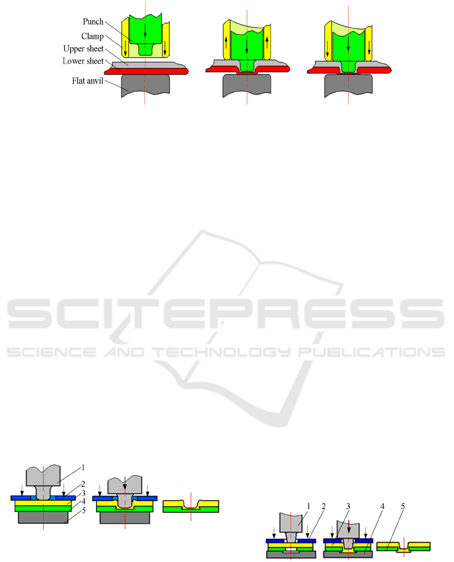
Figure 1: Principle of dieless clinching.
forced to flow in radial direction, thus forming an
interlock between the sheets. Compared to joining
by forming processes with a contoured die, dieless
joining has the following features (
Neugebauer, 2005
):
the wear of mold is low, the accuracy of the joining
equipment is less, and don’t require alignment, the
process reliability is high, but the joining force is
higher and the combined thickness of the connected
sheets is limited.
2.2 Flat Clinching
Figure 2 shows the process of flat clinching
(Neugebauer, 2007). The flat clinching is based on
the same principle as dieless clinching. The
components required for joining are the punch 1 ,
blank holder 2 , joint sheets 3and 4, the flat anvil 5.
Firstly, the two joined sheets are placed up on a flat
anvil. Afterwards, the blank holder moves down and
fixes the sheets in place. Subsequently, the punch
moves down and forms the material to establish the
characteristic interlocking within the total material
thickness.
Figure 2: Principle of flat clinching.
In contrast to other clinch connections, the
material flow is opposite to the punch movement
during the process, a one sided planar connection is
created that does not show the die-sided protrusion
reaching out of the material plane, so the flat
clinching can be used for the connection of metal
sheets to nonmetal sheets.
2.3 Hole Clinching
Schematic diagram of hole-clinching as shown in
Figure 3 (Chan-Joo, 2014), it is similar with the
process of flat clinching. The parts for the
connection are the punch 1, the holder 2, the upper
sheet 3, the lower sheet 4 and the die 5 with the
circular groove. In the hole-clinching process, the
ductile material is positioned uppermost and the
brittle material-into which a hole is formed is
positioned below that. At first, the holder presses the
upper sheet, and the upper sheet is squeezed into the
gap between the punch and the lower sheet. when
the upper sheet contacts the die bottom, it is
indented into a die cavity through the hole in the
lower sheet and spread out to fill the cavity in the die
to form geometrical interlocking.
Figure 3: Schematic diagram of hole-clinching process.
The hole-clinching is suitable for joining
different sheet in mechanical properties, but the
material with reduced formability on the die-side
must be pre-punched and the costs would increase;
there are protrusions at the joints and joints cannot
be created if the lower sheet is too thick.
2.4 Flat Hole-Clinching (FHC)
The principle of flat hole-clinching as shown in
Figure 4 (Tong, 2016). The flat is based on the same
principle as hole-clinching. It is different from the
hole-clinching, the hole of the flat hole-clinching is
stepped or inverted conical, there are not protrusions
at the joints too. This technique is fit for connecting
two layers of metallic sheets with dissimilar
materials and thicknesses by adding additional parts
to adjust the depth of the hole.
Figure 4: The principle of flat hole-clinching.
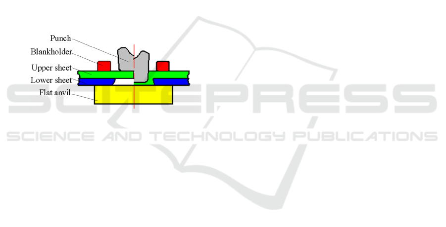
2.5 Injection Clinching
A detailed illustration of the injection clinching
process is shown in Figure 5 (Abibe, 2011). For the
material flowing during the process, there is a round
cavity at the bottom of the blank holder, a gap
between the hole and the stud that the lower plate
with a deformation element (normally a cylindrical
or cone stud). firstly, the joined sheets are assembled
together, inserted into the hole of the upper sheet,
the blank holder moves down and clamps the joined
plates with designed pressure; Afterwards, the punch
moves down to the plates and applies forming
pressure on the stud, to force it into the cavity in the
blank holder and the upper plate’s hole; then the
forming pressure is maintained to fully fill the round
cavity and gap; finally, the punch retracts and the
joint is formed.
In This technology creates a rivet by using part
of the structure itself, resulting in weight savings and
improved mechanical reliability. It is suitable for the
connection between metal to metal, metal to non-
metallic material (e.g. metal and thermoplastic
material).
2.6 Hydro-Clinching
Figure 6 shows the forming process of hydro-
clinching (Neugebauer, 2008), it is made up of the
punch 1, hydroforming tool 2, jointed sheet 3,
hydroformed sheet 4 and fluid 5. Firstly, the
hydroformed sheet and the jointed sheet are brought
in contact to the hydroforming tool by the fluid.
During calibration the fluid works as a punch to
press the hydroformed sheet through a hole in the
jointed order to avoid bursting and to ensure a higher
forming level at the produced protrusion, the punch
is withdrawn. Subsequently, the punch is set towards
the high pressure fluid. Because the back forming is
prevented by the high pressure fluid, the material
that has been pressed through the hole is spread and
formed an interlock at the chamfering of the
connected sheet. During joining process, the punch
is not moving, the interlock forms automatically at
the hole chamfering of the joined sheet when the
hydroformed sheet is pushed through the hole.
The hydro-joining process decreases the number
of processing steps and can join in complex
hydroformed units and inaccessible places, but the
device needs to be sealed and higher pressure when
connecting thick sheets.
2.7 Roller Clinching
The schematic setup for rolling clinching is depicted
in Figure 7 (Daniel, 2014).
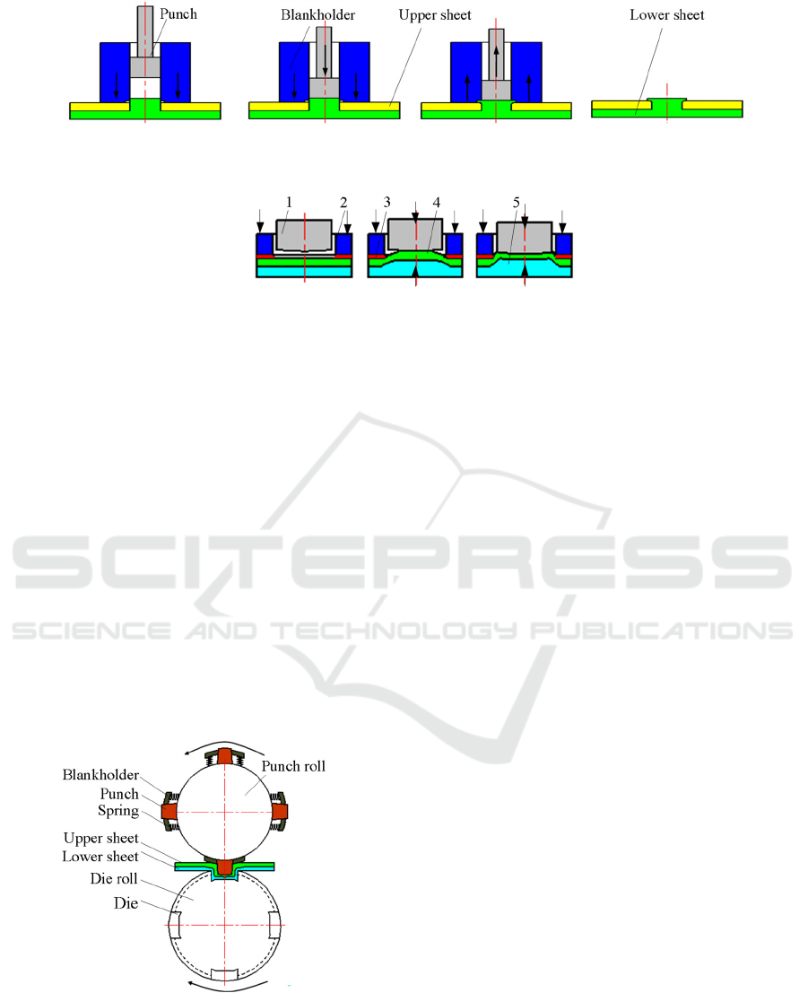
Figure 5: The stages of the injection clinching process.
Figure 6: The forming process of hydro-clinching.
The movement of punch is only rolling. Punches and
dies are mounted on contrariwise rotating rolls.
During clinching, the punch roll and die roll rotate
contrariwise, with the angular velocity and the sheet
is continuously fed through the rollers. A spring-
suspended blank holder prevents the material from
an extrusion out of the die cavity. It ensures a proper
separation of the obtained clinching point from the
tools. This process can be divided into four distinct
phases: initial contact, drawing phase, forming the
undercut and retraction.
The rolling radius have significant influence on
the joint formation and therefore on the joint’s
mechanical properties for the employed material
combinations, and the variation of the rolling radius
will result in an symmetry of the neck or the
undercut.
Figure 7: The schematic setup for roller clinching.
3 MULTI-ACTION CLINCHING
The multi-action clinching is that the movement of
punch is multy during the clinching, there are
rotational motion and vertical motion and so on. It
mainly cludes friction clinching and spinning
clinching.
3.1 Friction Clinching
The friction clinching is that the punch rotates at a
given speed and plunges the material (under load
control) up to reaching a given depth; then, the
punch is retracted up to the initial position to finish
the clinching, as shown in the Figure 8 (Lambiase,
2017). Due to the rotation of the punch, so the
friction between the punch and the connected sheet
material is produced, that the connecting plate is
heated and the join-ability is greatly improved.
The friction clinching can be used on highly
reflective materials (such as aluminum and copper
alloys), the heating is confined in the joint position
so the plunging force is dramatically reduced, and
the development of cracks in the aluminum alloy
was delayed or even avoided.
3.2 Spinning Clinching
The principle of spinning clinching is shown in
Figure 9 (Zhi-chao, 2011). It is composed of the
punch 1, blankholder 2, upper sheet 3, lower sheet 4
and die 5. The punch turns around the axis in an
acute angle continuously and vertically downward to
exert pressure on the sheet to form interlock during
the clinching process. Compared with the ordinary
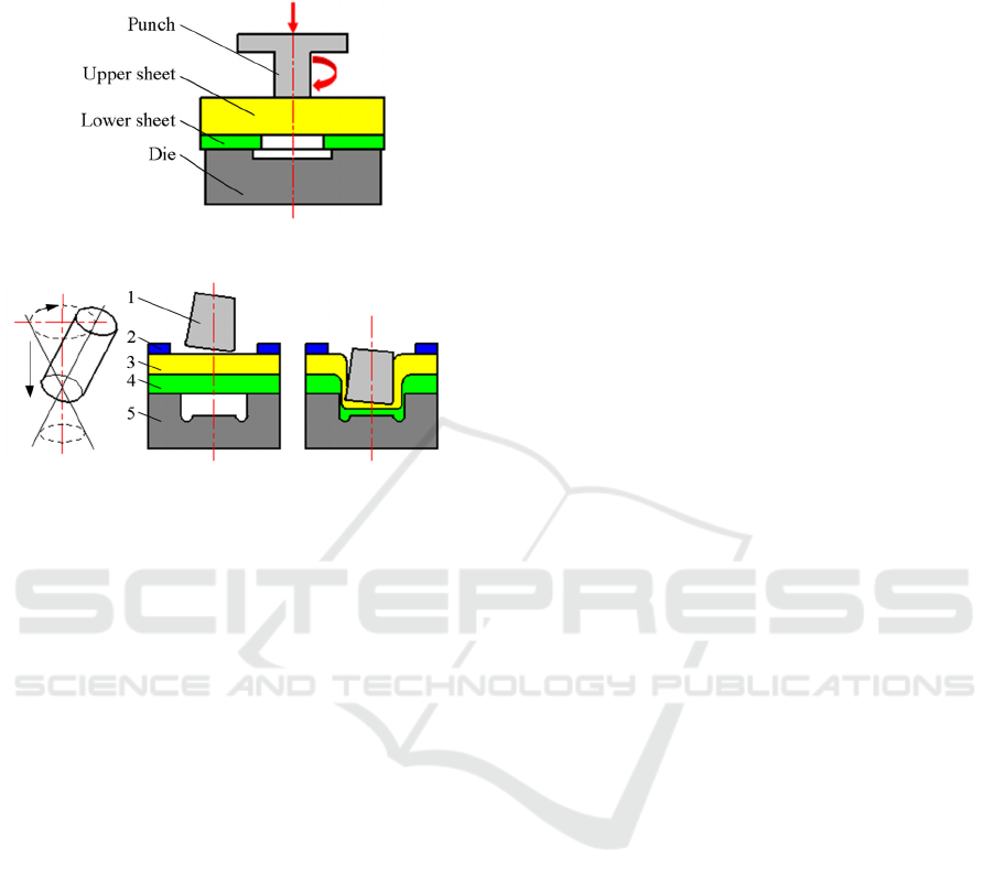
clinching, the spinning clinching has the advantages
of larger interlock value, smaller forming load and
higher efficiency, but the joint exists an asymmetry.
Figure 8: The principle of friction clinching.
Figure 9: The principle of spinning clinching.
4 CONCLUSIONS
In addition to the above the mechanical clinching
technology of the sheet, there are some other
auxiliary connection technology, such as ultrasonic
assisted clinching , laser clinching, vibration assisted
clinching, etc. The main purpose of these methods
are to increase the strength of joint, to improve the
connection quality and decrease the forming force
and to join the different sheets. No matter what kind
of methods, the strength of joint has a great
relationship with the geometry of clinched joint,
while the technological parameters, geometric
parameters and material flow have important effects
on the joint shape and size, therefore, it is necessary
to find some new connection methods to further
research by using numerical simulation calculation
and experimental method.
ACKNOWLEDGMENT
The authors would like to acknowledge the support
of Guangxi Natural Science Foundation
(2015GXNSFBA139223) and Guangxi university
student innovation and entrepreneurship training
program (201610595088).
REFERENCES
1. Neugebauer R., Reimund Neugebauer, Dietrich S.,
Kraus C., 2007. Dieless clinching and dieless rivet-
clinching of magnesium. Key Engineering Materials.
2. Neugebauer R., Mauermann R., Dietrich S., 2005.
Chances and challenges in joining by forming with flat
a counter tool. Advanced Materials Research.
3. Neugebauer R., Reimund Neugebauer, Dietrich S.,
Kraus C., 2007. Joining by Forming With a Flat
Counter Tool – a New Way of Joining Magnesium
Components. Materials Science Forum.
4. Chan-Joo L., Jung-Min L., Ho-Yeon R., et al, 2014.
Design of hole-clinching process for joining of
dissimilar materials Al6061-T4 alloy with DP780 steel,
hot-pressed 22MnB5 steel, and carbon fiber reinforced
plastic. Journal of Materials Processing Technology.
5. Tong W., Qian H., Qing L., et.al, 2016. Joining
different metallic sheets without protrusion by flat
hole clinching process.Internationa Journal Advanced
Manuf acutoryTechnology.
6. Abibe AB, Amancio-Filho ST, Dos Santos JF, et al,
2011. Development and analysis of a new joining
method for polymer-metal hybrid structures. Journal
Thermoplast Composite Mater.
7. Neugebauer R., Mauermann R., Grützner R., 2008.
Hydrojoining. International Journal of Material
Forming.
8. Lambiase F., Paoletti A., Di Ilio A., 2017. Advances in
Mechanical Clinching Employment of a rotating tool.
SHEMET17, 17th International Conference on Sheet
Metal, Procedia Engineering.
9. Zhi-chao H., Zu-feng Q., Lian-hong P., Jia-mei L.,
2011. Comparison of Numerical Simulations Between
Spin Clinching and Ordinary Clinching. Coal Mine
Machinery. (In Chinese)
10. Daniel R., Maria W., Hartmut H., 2014. Simulation
Assisted Analysis of Material Flow in Roller Clinched
Joints. Advanced Materials Research.
