
Research on Stability of Shafting Under Two Kinds of Impact Load
Tianran Chen
1
,
Liangxiong Dong
1
and Yiran Shi
1
1
ZheJiang Ocean University, ZhouShan 316022, China
Keywords: Ship shafting; rub-impact load; vibration; stability time
Abstract: The influence of rub-impact loadsupon the stability of shafting is directly related to the damage of ship
propulsion system, so the numerical simulation and experimental technology is applied to the studyon
stability of ship shafting under rub-impact load. Based on the dynamics model of stern shaft - oil film - stern
structure system, the amplitude-time response curve are obtained by the numerical simulation. On the basis
of theoretical researches, the tests of stability time under two kinds of loads are carried out. In addition, the
effective method to shorten the shafting stability time under rub-impact load is obtained that are provided
for the safe operation of shafting.
1 INTRODUCTION
Ship in the voyage, affected by the harsh
environment, the hull under external forces will
produce uneven deformation and random movement,
resulting in hull deformation, bearing oil film
whirling and the unstable state of shafting, So,
restraining or weakening ship vibration is the key to
strengthen the stability of shafting and improve
transmission performance. In this paper, by
numerical simulation and experimental, the variation
law of ship shafting stability under different load
and rotational speed is studied, the characteristics of
longitudinal vibration are analyzed, and the effective
method is found to shorten the time spent in
restoring the stability of the rear axle system. It
provides some theoretical basis for the optimization
design of ship construction and reasonable
installation of shafting, and strengthens the safety of
ship in the course of navigation.
2 STABILITY ANALYSIS OF SHIP
STERN SHAFT UNDER
EXTERNAL FORCE
In view of the complex stress state of ship shafting,
it has important theoretical significance and
application value to carry out the research of
shafting stability. There are two kinds of dynamic
load on the ship shafting, one is the impact load of
which the duration is very short and the energy
release quickly. The other is the cyclic dynamic load
of which the most common is the rub-impact load.
Under the action of Impact load some
significant changes may be made in the axis
trajectory. Therefore, through the axis trajectory can
obtain the stability of ship shafting and then judge
the rationality of the shafting parameters design.
According to the idea of discrete modeling, the
hull stern structure is discretized firstly, the discrete
stern structure is linearly elastic, and the tail shaft
system is simplified as a single disk system. So, the
corresponding mechanical model is set up
[1-3]
as
shown in Figure 1.
In Fig.1, the M1,M2 is the mass of the left and
right axle neck; the M5 is the mass of disc; the C1 is
the damping coefficient of the hinge at the bearing
place; the C2 is the damping coefficient of the hinge
at the disk; the C3 is the stern structure damping
coefficient; the K1 is the elastic axis rigidity; The
K3,K4,K5.is the connection stiffness of stern
structure. The values of the parameters
are:
1
100mkg=
,
2
80 ,mkg=
,
3
200mkg=
,
1
5000 . /cNSM=
,
6
510 /kNm=×
,
6
510 /
c
kNm=×
,
0.2cmm=
,
0.06rmm=
,
0.2mm
δ
=
,
0.1f =
,
7
3
510k =×
,
7
4
510k
π
=×
.
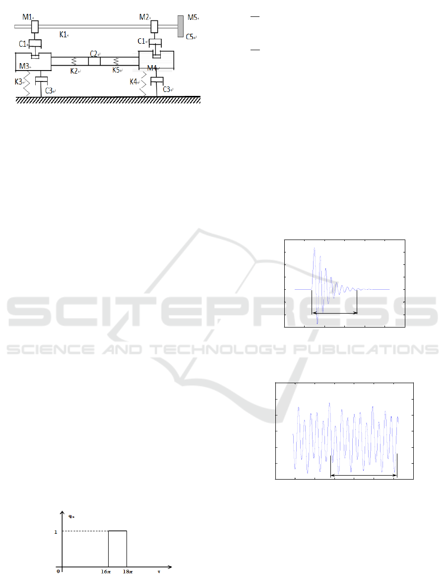
Fig.1 The mechanical model of ship shafting.
The dynamic equations of the rotor system are:
()
M
uCGuKuF++ + =
&& &
(1)
Where in,
u
is the displacement array,
F
is the
excitation force array,
M
is the mass matrix,
G
is
the gyro matrix,
C
is the damping matrix, the
K
is
the stiffness matrix.
3 THE SIMULATION OF
STABILIZATION PROCESS
UNDER IMPACT LOAD
Under normal operating conditions, the axis
trajectory is most sensitive to the change of
rotational speed that transferred between the
convergence and the divergence state [4-7].The axis
trajectory tends to deviate from the original motion
trajectory when the disturbance occurs, and
the time it takes to stabilize are not the same under
different disturbances. Therefore, this paper mainly
analyzes the change of the axis trajectory in two
cases, one is the change of the axis trajectory under
the condition of impact load, the other is under the
condition of rubbing load.
In the course of navigation, the propeller and the
hull withstand the external forces and thus the
movement of the shafting are influenced. The impact
load acting on the axis can be described as a
rectangular pulse load shown in Fig. 2.
Fig.2Impulsive load fig.
0, <16
1, 16 18
0, 18
0
x
y
q
q
τπ
πτ π
τπ
⎧
⎪
=≤≤
⎨
⎪
>
⎩
=
(2)
Under the condition of impact load, with the
increase of excitation frequency, the system presents
the state of transition from stable motion to periodic
motion and chaos motion. Accordingly, the
topological structure of vibration system will be
changed correspondingly. Two kinds of shafting
working condition, i.e., periodic motion and chaotic
motion, is analyzed and simulated of which the
corresponding rotational speed is 760r/min and
800r/min. The axial-cervical vibration response is
shown in Fig. 3-1andFig. 3-2in which the arrow
segment indicates the time required to restore
stability.
1560 1580 1600 1620 1640 1660 1680
-0.68
-0.67
-0.66
-0.65
-0.64
-0.63
-0.62
-0.61
T(s )
Amplitude(mm)
stability time
Fig3-1
1540 1560 1580 1600 1620 1640 1660 1680
-0.395
-0.39
-0.385
-0.38
-0.375
-0.37
-0.365
Amplitude(mm)
T(s )
Stability time
Fig3-2
Fig.3Thevibration response at speed of 760 and 800r/min.
Fig.3 show that the impact load has a certain
disturbance effect on the axis trajectory. The more
intense the impact load become, the longer the larger
the amplitude of shafting become. As shown in
Fig.3-1, the stable time is 120 when the rotational
speed is 760r/min, but the stable time become 140 at
speed of 800r/min as shown in Fig.3-2.Therefore,
under the same impact load, choosing the
appropriate rotational speed can effectively shorten
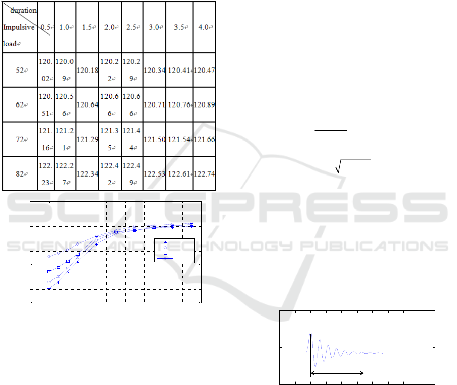
the stabilizing time. And then, keeping the speed
constant and changing the magnitude and duration of
the impact load, the stable time under various impact
loads at speed of 760r/min is measured in table 1:
Table.1 The stability time under different impact loads.
1 2 3 4 5 6 7 8 9 10
0.2
0.25
0.3
0.35
0.4
0.45
0.5
0.55
Emagnitude impact load(KN)
()
Ampli t ude mm
T=0.8pi
T=1.2pi
T=1.5pi
T=2pi
Fig 4Thestability time changed with magnitude and
duration of impact load.
The curve fitting is done according to
the sheets data as shown in Figure 4, that is the
variation curve of stability time according to the
magnitude when the duration of impact load remain
constant. It can be seen that the stabilize time of
shafting is different in different impact load, and the
change speed of stabilize time is related to the
magnitude of impact load.
4 ANALYSIS OF THE STABILITY
OF THE TAIL SHAFT UNDER
RUBBING LOAD
4.1 Simulation of Stability Process Under
Rubbing Load
Rubbing load is a kind of working condition caused
by the contact each other between tail shaft and tail
bearing in the process of ship operation. When the
rub occurs, the tail shaft and the tail will bear not
only the collision force but also the circumferential
friction force. Assuming the elastic deformation
happen in the collision process, and the gap between
the tail shaft and the tail bearing is
δ
, the rub force
can be expressed as:
1
()
1
x
c
y
P
f
x
ek
P
f
y
e
δ
⎧⎫
−
−
⎡
⎤⎧ ⎫
⎪⎪
=−
⎨
⎬⎨⎬
⎢⎥
⎪⎪
⎣
⎦⎩ ⎭
⎩⎭
(3)
Where in,
22
exy=+
is the radial
displacement of the shaft. When
e
δ
<
,both the
radial force and tangential friction are zero.
In the same way, make the friction coefficient of
the rub is 0.1 and the gap
δ
is 0.0002, meanwhile
keep the rub load and its action time constant, and
change the shafting speed. When the shafting
rotational speed is respectively760 and 800r/min, the
stability time and the vibration amplitude under
different working conditions are measured. as shown
in Fig. 5-1 and Fig. 5-2.
1570 1580 1590 1600 1610 1620 1630 1640 1650 1660 1670
-0.65
-0.6
-0.55
-0.5
-0.45
stablity time
T(s )
A m plitude(m m )
Fig 5-1
1540 1560 1580 1600 1620 1640 1660 1680 1700 1720 1740
-0.401
-0.4005
-0.4
-0.3995
-0.399
-0.3985
-0.398
-0.3975
-0.397
-0.3965
Amplit ude(mm)
T(s )
stabl ity time
Fig 5-2
Fig.5The vibration response at speed of 760 and 800
r/min,
It can be seen that the change of the rotational speed
of the ship shafting will affect the stability of the
axis track when the rub load is constant. With the
increase of the shafting speed, the dynamic
characteristics of the bearing oil film force are
changed, and the amplitude of the disturbance
caused by the rub load is also increased. In addition,
the changes of friction coefficient also has a certain
effect to the shafting vibration. The larger the
friction coefficient of rub become, that is, the bigger
the spring stiffness, the more intense the longitudinal
vibration of the shafting become, and the larger the
vibration amplitude of shafting. Therefore, subjected
to the same rub load, the stability time of the
shafting system can be effectively shorten by
adjusting the rotational speed and selecting the
appropriate friction coefficient .
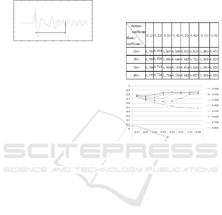
4.2 Comparison of Shafting Stability
Between Two Kinds of Load
In order to compare the stability of the tail shaft
under variousrub load, keeping the rotational speed
unchanged and just changing the friction coefficient
and elastic coefficient of rub-impact load, the
stability time is observed and recorded in table 2.
The data from Table 2 is shown in Figure 6.
The Fig. 6 shows the change curve of the elastic
coefficient according to the increase of the friction
coefficient. It can be seen that the change speed of
stabilize time is different in different friction
coefficients, that is, the lower the friction coefficient
is, the smaller the growth rate of stabilize time is
likely to be. For example, when the elasticity
coefficient is 150, the shafting have the fastest
recovery speed. When the coefficient of friction is
less than 150, the greater the elasticity coefficient is,
the greater the time needed for the stability of the
shafting system, which is come to opposite
conclusions when the coefficient of friction is more
than 150.
Table 2TheStability time under different loads .
Fig 6The stability time changed with friction coefficient
and elasticity coefficient
5 CONCLUSIONS
In this paper, the dynamic model of the stern shaft -
oil film - stern structure system is established, and
the stability characteristics after impact and rub are
studied, which provides a theoretical reference for
the safety evaluation of the shafting.
1. The impact and rub load will disturb the
motion of ship propulsion shafting with compromise
in stability which extent is related to the axis speed.
In the non periodic moving region, the prolongation
of the load duration will lead to the amplitude
decays slowly and the ability restore the stable state
of shafting become weak. On the other hand, in the
periodic motion area the amplitude decays fast, and
the more shaft's rotational speed deviates from the
frequency area farther, the faster the amplitude
decays, and the better the stability recovery of
shafting system.
2. Compared under the influence of impact load,
the shafting under the influence of rub load can
recovered to steady state within a shorter time. By
adjusting the rotational speed of shafting, the

damage effect of rub-impact on shafting can be
weaken. Meanwhile, by increasing coefficient of
friction will shorten the stability time of the tail
shaft, and thus strengthen the stability of the ship
shafting.
ACKNOWLEDGEMENTS
This research was supported by Zhejiang Provincial
Natural Science Foundation of China under Grant
No. LY16E090003; The National Undergraduate of
China Innovation and Entrepreneurship Training
Program (NO. 201703440007).
REFERENCES
1. Numerical Analysis of Transverse Shock Response of
a Ship Shaft Taking Dynamic Stiffness of Supports
into Consideration[J].LI Xiao-bin, DU zhi-peng, XIA
Li-juan, JIN Xian-ding. JOURNAL OF VIBRATION
AND SHOCK, 2006(02)
2. THOMSON W T , DAHLEH M D. Theory of
vibration with application(Fifth Edition)[M]. Upper
Saddle River:Pren-tice-Hall,1998.
3. WEIGHTED FINITE ELEMENT METHOD FOR
COMPUTING NONLINEAR OIL-FILM FORCES IN
JOURNAL BEARING [J]. WANG Li-ping, LIU Da-
quan, ZHANG Wen, ZHENG Tie-sheng.
ENGINEERING MECHANICS. 2006(05)
4. Hawkings,Seth. The use of maneuvering propulsion
devices on merchant ships[ R].Report RT- 8518,
Contract MA-3293, 1965.
5. [5] Research on Analytical Model of Sliding Bearing
Nonlinear Dynamic Oil-film Force [J].YANGJin-fu,
YANG Kun, FU Zhong-guang, CHEN Ce, CUI Ying,
YANG Sheng-bo. LUBRICATION ENGINEERING.
2007(09)
6. KITIS L, WANG B P, PILKEY W D. Vibration
reduction over a frequency range [J].Journal of Sound
and Vibration, 1983, 89(4): 559~569.
7. Influence of Ocean Waves on Ship Propulsion Shaft
[J]. LU Jin-ming, ZHOU Hai-gang, DING Li-bin,
BAO Su-ning, MA Jie. JOURNAL OF SHANGHAI
JIAOTONG UNIVERSITY. 2010(10).
