
A Single Prepaid Electricity Meter with LoRa Communication
Module
Dong Yan
1
, Kai Zhang
2
1
College of Automation, Chongqing University of Posts and Telecommunications, Chongwen Road, Chongqing City, China
2
College of media and art, Chongqing University of Posts and Telecommunications, Chongwen Road, Chongqing City,
China
Keywords: Single Phase Watt Hour Meter; LoRa; Prepayment; Energy Metering
Abstract: In order to achieve the goal of long-distance communication, low power consumption and lowcost of single-
phase prepaid energy meter, this paper presents a single-phase prepaid energy meter with LoRa
communication module based on the analysis of the existing energy meter communication methods.The
LoRa communication module uses the SX1278 chip, which is briefly introduced in this article.The single-
phase prepaid energy meter added to the LoRa communication module is powerful and has broad
application prospects.
1 INTRODUCTION
With the development of Smart Grid, the Prepaid
electric energy meter is promote and popularize
widely. At present, the main recording way of wire
communication includes power line carrier
communication and RS485 communication. The
subsistent power grid could utilize Power line carrier
communication to finish, which do not need extra
investment of layout and in low price. Otherwise,
there are several shortcomings about it, such as loud
intermittent noise (Starting and stopping or working
time of electric appliance), fast signal attenuation,
circuit fluctuation and impedance etc. RS485
communication system is easily to operation to
ammeter record. However, great workload and high
priced maintaining, frequent circuit burn-in and
damage are big problems. GPRS and ZigBee is
major communication for power information
acquisition。GPRS could spread over great distance
with super security and stability as wireless
constructed through telecom operator. Construction
of base station is a precondition of GPRS. Building a
base station require a big sum of funds and should
pay high maintain cost. So we could know this
technology is not adaptive used in remote and rural
area because there are not strong signal. Although
we could decrease the cost of base station
construction depend on ZigBee wireless
communication, short-distance communication limit
the function of the technology. It is not suit to spread.
Thus we should find a new way to deal with
meter record, it must keep in low cost and energy
consumption meantime, can finish long-distance
communication. LoRa possess these characters, it is
a new wireless communication technology with low
energy consumption and cost, moreover has
extremely well network Extensibility and
communication ability. LoRa be used in free
frequency that is non-authorized band, include
433MHz、868MHz、915MHz etc. Because of the
minimum receive current about 10mA and sleep
current less than 200nA, we could utilize advanced
Spread spectrum modulation technology and coding
way to enhance Anti-jamming performance and
increase link budget. LoRa could enhance the
stability of Deep fading and Doppler shift, it can
received the communication distance up from 15km.
So we could know the LoRa communication
technology have so extremely excellent performance
that meter could be promote widely.
2 LORA COMMUNICATION
ELECTRIC CIRCUIT
LoRa communication chip be product by
Semtechcompany in USA. The chip and transceiver
circuitconstitute the module of Wireless transceiver.
The main disposal system of SX1278transceiver is
LoRaRemote modem, it could be used in long-
distance spread spectrum communication with
strong anti-interference performance and reduce
current consumption. Depend on LoRatechnology,
SX1278 in the low price crystal and material have
more higher sensitivity than 148dBm. It is become
the best choice of long distance communication and
high-tech applications.
LoRa modem technology have remarkable
advantage in diffraction, it tackle the problem of
long distance, weak anti-interference ability and
large energy consumption. Compared with similar
products, SX1278 not only reduce electric current
consumption also optimize the function of phase
noise、 Selectivity, receiver linearity, 3order input
interception(IIP3), as fig.1 and fig.2.
Fig.1 SX1278 pin.
Fig.2LoRa wireless module.
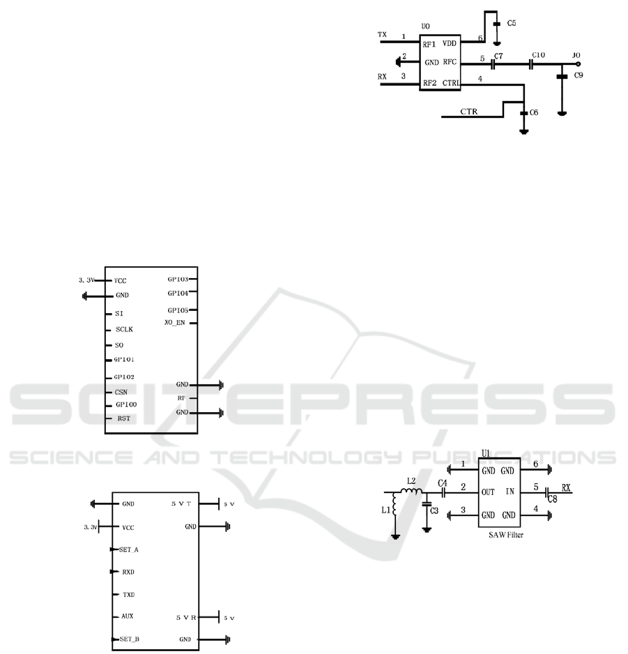
2.1 SX1278 Receive and Transmission
Switch Circuit
The fig.3 show the operating principle of SX1278
reception and transmission switch current. It is half
duplex communication chip, so it must work in one
alternative pattern of data reception or transmission.
The behalf of radio switch, it could work in data
reception or transmission pattern through control the
level of CTRL pin and VDD pin.
Fig.3 Radio switch circuit.
2.2 SX1278 Receive Circuit
The fig.4 illustrates the construction of SX1278
reception current. L1, L2, C3, C4 are components of
filter. Base on the really communicational frequency,
these parts could choose suitable parameter. Because
different electrical applicants be used in there, the
actual wireless communicational environment is
complex-the radio signals of various frequencies
could be received through antenna. This situation
will impact the distance of communication. In this
picture, U1 is SAW filter that be used for filter the
frequency signal of outside could make Specific
frequency signal through. If there are not SAW
Filter, external signal can interfere the work of
SX1278.
Fig.4 SX1278 receive circuit.
2.3 SX1278 Transmission Circuit
The content of fig.5 about SX1278 transmit circuit,
which consist of several filters. L3 and C11
constitute the series resonance current. C16, L5 and
C17, L6 construct two group of Parallel resonance
current. The equipment could choose suitable device
parameter according to different communication
frequency.
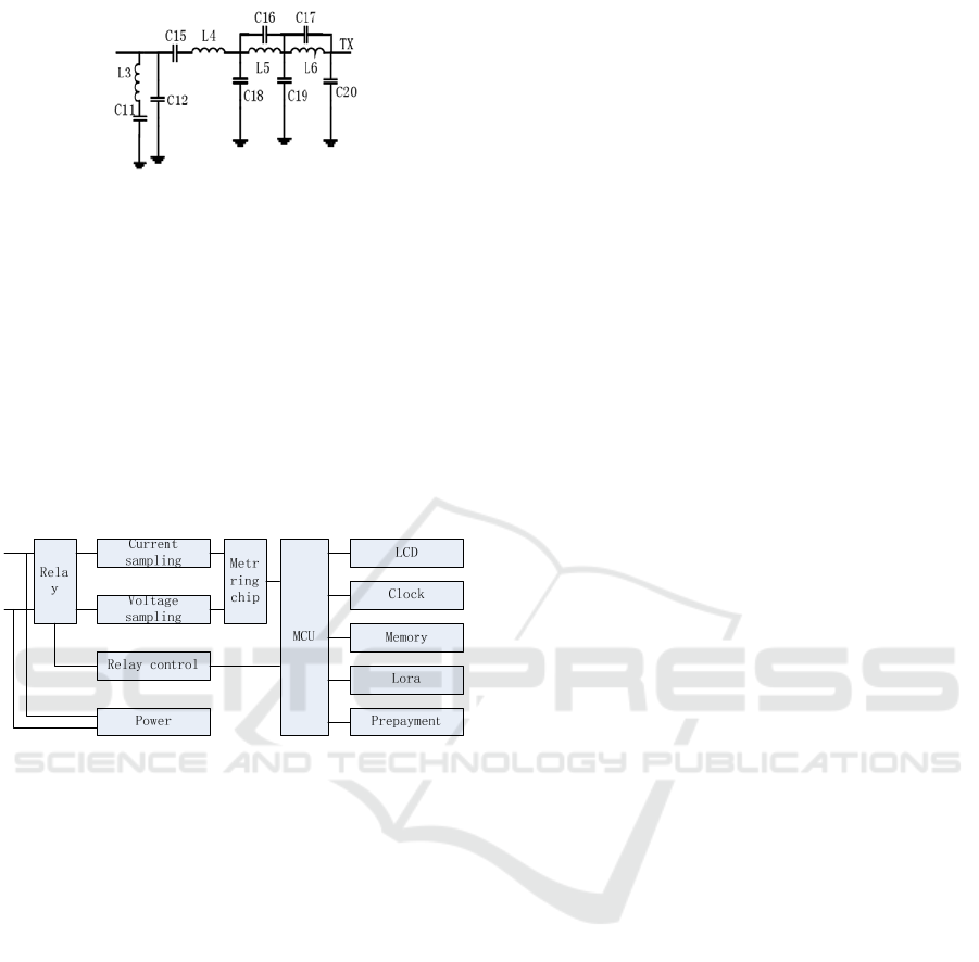
Fig.5 SX1278 transmission circuit.
3 OVERALL DESIGN SCHEME
In this paper, a sort of Monophasic prepaid electric
energy meter with LoRa communicational module
be accepted, which include micro-processor, basic
module, Electric energy metering module, relay
controlled module, power module, pay-in advance
module, LoRa communicational module. The way of
connection showed like fig.6.The function of
different modules as follows:
Fig.6Design scheme.
3.1 MCU Module
Micro-Control Unitis the key device of meter, it
could connect other modules as a uniform system
through powerful compute ability. In this process,
Electric energy meter, data display, relay control and
prepayment control of electric energy meter and
wireless communication function could be finished.
3.2 Basic Module
The basic module include LCD unit, clock unit,
memory unit,direction unit, pulse output unit. The
LCD unit used for display the data of different fee
ratio in Accumulative energy and total data of
Accumulative energy, moreover, including The
maximum demand. The direction, date, term,
Accumulative energy , the information of relay
communication signal, pay-in advanced information,
address etc.
Clock unit consist of Built-in hardware clock
circuit with temperature compensation function that
can transfer the date and time automatically. The
outputting frequency of inner clock port is 1Hz
(among the temperature range about-25℃~+60℃),
and the accuracy rating of clock ≤±3s/d (under the
23℃,the accuracy rating of clock≤±1s/d).
Store unit used EEPROM that can erasure
1million again. It can Save power, area code,
numbering, and other data and states so that these
data cannot lose after power cut.
Direction unit used LED as instructional light, in
there, the pulse direction light is red, it does not
blink in normal time, but blinking on the time of
measurement of active power. Alarming light also is
red, it will blinking only in alarming time. Trip
instruction light is yellow, it blinking in the time of
Load switch.
3.3 Electric Energy Module
The electric energy metering module includes
Current sampling, voltage sampling and energy
metering chip. The main duty of current sampling is
sampling of neutral wire and live wire. Voltage
sampling gathers the sample of voltage between
neutral wire and live wire. Electric energy metering
chip could collect voltage and current signal through
the process of enlargement of gain amplifier. And
then it will transfer analogue signal into digital
signal through AD converter. After filter the result of
active power could be get through the way of current
statistics multiply by voltage statistics. This
information will be submitted to micro-processor in
the form of high pulse.
3.4 Relay Control Module
Relay control module include relay and control
which main function about control the circulation
turn on or off. The microprocessor will give
disconnect command, when it receive the signal
submitted by upper computer about delinquent fee.
After MCU sent disconnect signal, relay control
reception instruction and then it execute the order to
interrupt the supply of power.
3.5 Power Module
Power module could be support by power line
supply and Li batter supply, in general condition,
power module supply electricity to meter through
power line. When power cut due to line fault, the Li

batter could support current to meter for keep work
of meter.
3.6 Prepayment Module
This part could fulfill prepayment function through
insert IC card. The main functions include:
Intelligent control: IC meter calculate energy
used of customer through pulse counter
automatically.
Pre-alarm function: If remaining power in the
record of IC card less than alarming quality, warning
signal will be sent. The user could purchase power
as soon as possible.
Load control function: when load continually
exceed the setting value of meter, the load switch
will disconnect automatically, which could protect
the circuit and facilities against destroy. When load
be limited in controlling range, meter switches off
automatically. It is convenient to customer.
Energy call-backs function: IC card will record
the data of remaining amount again for supporting
inquiry of manage system, when user insert IC card
in machine every time.Please remember that all the
papers must be in English and without orthographic
errors.
Security protection function: it use memory cards,
encryption cards, CPU cards as a power purchase
card, key security authentication in the IC card and
meter, which has a high degree of security. In this
way, a household only has one card and each
purchase card only valid once.
Replacement card function: When the electric
card lost, the clerk can replenish the electricity
generation card for the user through the electricity
sales network.
Inspection function: The electricity sales network
can issue inspection cards and regularly check the
operation of the user's IC card and meter.
Electricity-freezing function: The power sales
department have right to freeze the amount of
electricity generated through the order of IC card,
then the frozen electricity data will write back to the
line loss statistics, meantime, electricity billing will
be computed.
Load statistics function: The power sales
department can issue a conduction of load freezing
to the IC card power meter through the data
communication channel. The IC card power meter
can calculate the user's power at a certain moment
according to the instruction,and then it can freeze
the information that transmit it to the power sales
department for resident power load analysis.
3.7 Lora Module
According to the analysis above, Lora module adopt
SX1278 chip product by Semtech Company in USA.
This chip and external transceiver circuit compose
LoRa wireless transceiver module. It could use in
data transmission meter send upper computer in
electric sale. Meantime, it could receive the data
coming from the power sales department. In this
process, the remote control of meter could be
finished.
4 CONCLUSIONS
In this paper, we analysed the advantage and
disadvantage of limited communication and wireless
communication, we could know that the most of
meter communication ways are not meet the
requirement of remote communication that must
have low power consumption, low-cost, long-
distance. So a sort of Single-phase prepayment
meter with LoRa communication module is inferred.
After brief introduction of a signal prepayment
meter with LoRa wireless communication module
(SPM-LWM), we generate a design schedule of
SPM-LWM,and introduce the function in different
module briefly. With the development of smart
power grid, this power meter has great applicability
in future.
REFERENCES
1. YuTian.Design of PLC Centralized Meter Reading
System[A].InformationEngineeringResearch
Institute,USA.Proceedings of 20133
rd
International
Conference on EducationandEducation
Management(EEM2013)Volume25[C]2013:6
2. Ti S.,Kaiqi S.,Jianhua L.New Technology and
Application of Electric Energy metering.China
Electric Power Press,2010.
3. Yiyan Y., Yongchang Z.A Brief Analysis of the
Development of Remote Meter Reading
Technology.Electronic production,2014,09:119+114.
4. Kuiying W., Zhanping L., Yanwei Y.HFC-based
Remote Automatic Meter Reading System
Architecture. Electronic Test,2013,18:59-61
5. Lewark U. J.,Antes J.,WalheimJ.,et al.Link Buget
Analysis ForfutureE-band Gigabit Satellite
Communicate Kinks. CEAS Space Journal,2013,4(1) :
41-46.
6. Mohamed A.,Axwl S. Free Range Measurements with
SemtechLoRa Technology.2014 2nd International

Symposium on Technology and Applications
( IDAACS-SWS).Offenburg,2014: 19-23.
7. Tianping G. Long Distance and Low Power Wireless
Communication Base on Lora Technology.
Electronics World,2016,82(10): 115-117.
