
Mineralization
K
inetics of Hydroxyapatite/Chitosan Composite in a
Simulated Body Fluid
Liping Zeng
1
, Deliang He
1
and Xianglong Liu
2
1 Department of Building Engineering, Hunan Institute of Engineering, Xiangtan, Hunan 411104,China
2 College of Chemistry and Chemical Engineering, Hunan University, Changsha, 410082, PR China
Keywords: Hydroxyapatite; Chitosan; Mineralization; Electrochemical impedance spectroscopy
Abstract: This study offers provide real time and multidimensional information to the monitoring of biomaterial
mineralization process. In order to investigate on real time the mineralization process of
hydroxyapatite/chitosan (HAP/CS) composite in a simulated body fluid, the piezoelectric quartz crystal
impedance (PQCI) technique and electrochemical impedance spectroscopy (EIS) was used to reveal the
mineralization kinetics processes for bone tissue engineering. Various characterization techniques were
analyzed by Fourier transformed infrared (FT-IR), X-ray diffraction (XRD) and scanning electrode
microscopy (SEM). A decrease of the frequency (f) and an increase of the charge transfer resistance (R
ct
) at
the gold electrode/solution interface were observed due to the mineralization of HAP/CS composite.
According to the data of the frequency and static capacity (C
s
), the correlative kinetic equations and
parameters were obtained by nonlinear regression. The results show that the mineralization process of
HAP/CS is divided into two stages: the nucleation stage and the crystal growth stage, which paves the way
for applications of bone tissue engineering.
1 INTRODUCTION
Calcium phosphates that have a similar chemical
composite with the mineral phase of natural bone are
excellent candidates for bone repair and have been
used in bone tissue engineering for two
decades(Baker et al., 2006;Shadanbaz et al., 2012;
Chen et al., 2014). Hydroxyapatite
(Ca
10
(PO
4
)
6
(OH)
2
, (HAP) is one of the most
important and most widely used among calcium
phosphate bioceramics because of its excellent
osteoconductivity and bone replacement
abilities(Liu et al., 2015; Cengiz et al., 2008;
Balasundaram et al., 2006; Wang et al., 2007.
However, HAP use for reconstruction of a load
bearing bone is limited by its brittleness. To improve
the use of the HAP, hydroxyapatite/chitosan
(HAP/CS) composite polymer-ceramic has been
proposed and widely investigated (Petro et al., 2016;
Pangon et al., 2016; Zhao et al., 2011). In recent
years, significant research effort has been developed
for preparation and characterization of HAP/CS for
bone tissue engineering(Jiang et al., 2008; Zhang et
al., 2012). HAP/CS nanocomposite rods have been
prepared by in situ hybridization, and their
mechanical properties of bending and compressive
strength properties are enhanced(Bayrak etal., 2017;
Lei et al., 2017). HAP/CS composite in-vitro
investigations of biological mineralization are very
useful for correctly simulating in vivo conditions,
since the assays allow investigators not only to
predict the behavior of bioactive implant biomaterial
in the body but also to understand the physical-
chemical background of mineralization. One of the
most important characteristics of these bioactive
artificial bone materials is that there is bone-like
carbonate apatite, which is chemically and
structurally equivalent to the mineral phase in bone
and provides an interfacial bonding between
materials and tissues. This apatite layer can be
formed during mineralization process in a simulated
body fluid (SBF) solution(Ohtsuki et al., 2010;
Shahriarapanah et al., 2016; Li et al., 2010).
Manjubala et al. reported the mineralization process
of nano-hydroxyapatite-chitosan by double diffusion
technique and analyzed the phase purity of apatite
using X-ray diffraction (XRD) and Fourier
transformed infrared (FT-IR) analysis(Manjubala et
al., 2006; Meng et al., 2015). Furthermore, several
studies have made efforts to accelerate the

mineralization process using modified simulated
body fluid(Kong et al., 2006; Ying et al., 2011;
Barrere et al., 2002). The traditional mineralization
evaluation is mainly based on static characterization
by XRD, FT-IR and scanning electrode microscopy
(SEM). Few real-time kinetic investigations have
been reported in the literatures. The piezoelectric
quartz crystal impedance (PQCI) technique is a
useful tool not just for providing multidimensional
information reflecting some physical and chemical
properties of the investigated system (Muramatsu et
al., 1990; Zeng et al., 2009; Sauerbrey et al.,1959),
but also for on-line monitoring the mineralization
process of HAP/CS composite in a SBF solution.
This work focuses on the kinetic process of
mineralization of HAP/CS composite in a SBF
solution. In addition to PQCI that helped analyze the
kinetic process and mechanism, the cyclic
voltammetry (CV) and electrochemical impedance
spectroscopy (EIS) were used to characterize film
surface. Furthermore, to obtain a comprehensive
understanding of the nucleation and growth of HAP,
the crystal structure and morphology were examined
by FT-IR and SEM.
2 MATERIALS AND METHODS
2.1 Materials
CS (molecular weight 2.0×10
5
) was supplied by the
Sigma Company, and the degree of deacetylation
and purity of CS are 89% and 98%, respectively.
AT-cut 8MHz piezoelectric quartz crystal (PQC) of
approximately 15 mm diameter with gold electrodes
(8 mm in diameter) was obtained from 704
Company (Beijing China). Calcium nitrate
[Ca(NO
3
)
2
·4H
2
O], diammonium hydrogen phosphate
[(NH
4
)
2
HPO
4
], ammonia[NH
3
·H
2
O],
tris(hydroxymethyl)aminomethane [C
4
H
11
NO
3
], 2-
mercaptoacetic acid [SHCH
2
COOH], and all the
inorganic salts for SBF solution and phosphate-
buffered saline (PBS) were obtained from Shanghai
Chemical Reagents (Shanghai, China). All the
solutions were prepared with deionized water.
2.2 Preparation of HAP/CS Composite
CS was dissolved in a 1% acetic acid aqueous
solution until a 1% (wt %) CS solution was obtained.
Nano-HAP particles were prepared as previously
described(Wang et al., 2004). Briefly, precipitate
was performed by the slow addition of a 0.5 M
ammonium phosphate water solution into a 0.5 M
calcium nitrate anhydrous ethanol solution with
stirring at room temperature. The pH value of the
solution was adjusted to 11 by NH
3
·H
2
O. After the
addition of ammonium phosphate ended, the
reactants were stirred for another 2 h, and then the
suspension was left to settle for 24 h. The precipitate
was washed with deionized water and finally with
ethanol. According to our previous work(Xu et al.,
2009), HAP/CS composite with mass ratio of (6/4)
can be mineralizated well in SBF solution. In this
experiment, HAP was dissolved into CS of acetic
acid aqueous solution based on this ratio and
ultrasonic dissolution for 30 min. Then the prepared
HAP/CS composite solutions were kept in a
refrigerator.
2.3 Preparation of SBF Solution
The SBF solution was prepared by dissolving NaCl,
NaHCO
3
, KCl, K
2
HPO
4
·3H
2
O, MgCl
2
·6H
2
O CaCl
2
,
and Na
2
SO
4
into deionized water. The SBF solution
was adjusted to physiological pH (pH 7.4) with tris-
HCl buffer. The SBF concentrations were 142.5 mM
Na
+
, 2.6mM Ca
2+
, 1.5mM Mg
2+
, 5mM K
+
, 147.8mM
Cl
-
, 1.0mM HPO
4
2-
, 4.25mM HCO
3
-
and 0.5mM
SO
4
2-
.
2.4 Preparation of PQC Sensor
In order to remove possible contamination, each of
the gold electrodes of PQC was cleaned in fresh
piranha solution (70% H
2
SO
4
, 30%H
2
O
2
) followed
by rinsing with deionized water. Then, self-
assembled monolayer was formed on the gold
electrode surface by immersing it into a solution of
0.01 M 2-mercaptoacetic acid for 12 h. Subsequently,
the HAP/CS composite was dropped on the surface
of gold electrode of PQC by a micro-syringe. The
electrode was put into an air oven to be dried at
60 ℃ for 24 h in order to remove all the acetic acid
and water, and then a rigid film was obtained.
2.5 PQCI Measurement
The mineralization process of HAP/CS composite
was monitored on-line using a piezoelectric
impedance analyzer (HP4192 LF, America). The
PQC sensor with modified (HAP/CS) electrode was
dipped in SBF solution at 37±0.5 ℃ . A user’s
program was developed using Visual Basic (VB) 5.0
to control the piezoelectric impedance analyzer,
which measures the resonant frequency (f) of the
PQCI simultaneously, and also fits the values of the
Butterworth-van Dyke (BVD) equivalent circuit
parameters by Gauss-Newton nonlinear least-
squares. In this work, the BVD equivalent circuit
parameters were obtained in 30 s intervals, including
motional resistance (R
m
), motional inductance (L
m
),
static capacitance (C
s
) and motional capacity (C
m
).
2.6 Electrochemical Measurements
The mineralization properties of the HAP/CS
composite were studied by electrochemical methods
using EIS and CV (CHI660B electrochemical
workstation, Instruments China CH). A conventional
three-electrode cell was utilized: a modified
electrode served as the working electrode, a
platinum plate served as the counter electrode, and a
saturated KCl calomel electrode served as the
reference electrode. All experiments were performed
at 37±0.5 ℃.
The variation of morphology and composition
for the corresponding stages of mineralization
products were characterized by FT-IR (Nicolet 5700,
Thermo), scanning electron microscopy (SEM, JSM-
6700F, Japan) and XRD (CO.. Ltd., Japan).
3 RESULTS AND DISCUSSION
3.1 PQCI Studies of Mineralization of
the HAP/CS Composite in SBF
Solution
The PQCI analysis technique is usually used to
study the on-line interface properties of surface-
modified electrodes. In piezoelectric analysis, the
frequency response change (Δf) of the sensor in
liquid depends on the mass and viscoelasticity
changes of the sensor surface, and the change in the
viscosity and density of the solution. Motional
resistance (R
m
) represents the loss in mechanical
energy mainly dissipated to the surrounding medium
and quartz interior. The change of motional
resistance (ΔR
m
) reflects the variation in the
viscoelasticity of the film and in the viscosity and
density of the contacting solution.
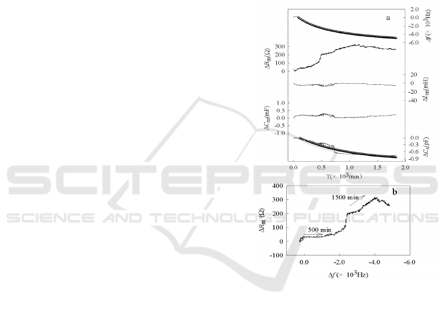
The typical PQCI response parameters (ΔR
m
, Δf,
ΔC
m
, ΔL
m
and ΔC
s
) during mineralization of the
HAP/CS composite in SBF solution are shown in
Fig. 1(a). It can be seen that as Δf and ΔC
s
decrease,
ΔR
m
increases, and ΔC
m
and ΔL
m
change modestly.
The decrease of Δf is due to the mineralization of the
HAP/CS composite in SBF solution; specifically
Ca
2+
and PO
4
3-
ions are coupled electrostatically
with carbonyl groups and amine groups of CS on the
electrode surface, thus increasing the mass of the
electrode surface film. In Fig. 1(b), the horizontal
line for the initial 500 min exhibits the mass binding
on the electrode surface(Marx et al., 2003). After
mineralization, HAP crystals gradually grow on the
surface of film, resulting in viscoelasticity change of
the film, which brings ΔR
m
increase and Δf decrease.
The slip of Δf versus ΔR
m
shows mass change and
energy dissipation properties.
Fig. 1. (a)Time course of simultaneous responeses of ΔR
m
,
Δf, ΔC
m
, ΔL
m
and ΔC
s
during the mineralization of the
HAP/CS composite in SBF solution; (b) Δf vs. ΔR
m
diagram for the mineralization of HAP/CS composite.
The static capacity, C
s
is related to the capacity
and structure of the electrical double layer at the
charge interface. ΔC
s
will provide the information
on the capacity and structure of the interface. In this
experiment, C
s
decreases gradually; this may be
caused by the mineralization of HAP/CS composite
that results in thicker film. Furthermore, the
deposited HAP covers the surface of HAP/CS
composite resulting in hydrophilicity decrease and
subsequent reduction in ion transfer. And, the
dielectric constant of the film also varies with HAP
formation. These factors combine to cause a
decrease of ΔC
s
.

The mineralization of HAP/CS composite in
SBF solution fits the two consecutive reactions
kinetic model. That is to say, the mineralization of
HAP/CS composite could be divided into
consecutive reaction steps. A conceptual model
advances carbonyl groups and amino groups of CS
as nucleation sites for HAP crystallization through
binding oppositely charged ions, calcium ion and
phosphate ion. Therefore, there is heterogenous
nucleation and growth of nano-HAP on the surface
of composite. Moreover, Ca
2+
ions enrich the
carbonyl groups and amino groups of CS in SBF
solution and PO
4
3-
enrich the amino groups of CS;
this enrichment may be attributed to electrostatic
interaction or/and polar interaction. Finally,
heterogeneous nucleation of HAP on the surface of
films forms crystals of HAP gradually. Due to OH
−
and CO
3
2-
doping in SBF solution, HAP crystalline
grew and formatted a biological active bone-like
carbonateapatite layer with mineralization times
increasing. The process of HAP crystal growth is
illustrated in Scheme 1.
Scheme 1. Schematic process of different steps involved
calcium phosphate crystals on HAP/CS composite.
3.2 SEM Characterization
Fig. 2 shows the SEM micrographs of HAP/CS at
12,000× after soaking in simulated body fluid for
various periods. In Fig. 2(a), porous structure is
observed before HAP/CS immersion. After
mineralizing for 500 min, white granules are found
in Fig. 2(b), which are HAP crystal consisting of
numerous tiny flake. It is considered that a single
layer of HAP particles start to deposit over the
surface. This microstructure corresponds to the
reported literature(Ramila et al., 2002; Zhu et al.,
2007). Then, at time of 1500 min in Fig. 2(c), the
surface is almost covered with calcium phosphate
particles accompanied by a secondary nucleation
over the initial layer. With increase of the immersion
time, the crystal grains congregate together and form
the porous HAP layer. Finally, the HAP crystal
grains fill in the porous HAP layer and grow a dense
structure in Fig. 2(d). Due to the HAP component of
the starting material, the HAP induced the new
nucleation and it grew vertically on the surface. This
microstructure corresponds to that deposited on a
bioactive glass or ceramics from SBF
solution(Oliveira et al., 2009; Davidenko et al.,
2010). To observe the typical HAP shape, it must be
at higher magnifications. Oliveira et al. reported that
it was possible a needle-like nanostructure for
characteristic of Ca-P coatings formed under the
present biomimetic conditions. Changes of
morphology and structure of various stages
demonstrate the nucleation and crystal growth.
Fig. 2. SEM images (12,000×) of HA/CS after soaking in
SBF solution at 0 min (a), 500 min (b), 1500 min (c), 2000
min (d).
3.3 Electrochemical Impedance
Investigation and Cyclic
Voltammetry Measurement
In order to clarify the difference among the
mineralization films of the HAP/CS composite,
electrochemical impedance spectroscopy and cyclic
voltammetry were carried out before and after
mineralization. Fig. 3 shows the electrochemical
impedance spectroscopy and cyclic voltammetry for
crystal modified with HAP/CS composite and the
crystal immersion in SBF for 12 h and 24 h,
respectively. The measurements were conducted in a
phosphate buffer solution (pH=7.4) containing 0.2
M NaCl, 1mM K
3
[Fe(CN)
6
] and 1mM K
4
[Fe(CN)
6
].
The semicircle region lying on the Z
re
axis included
in the electrochemical impedance spectroscopy
corresponds to the electron transfer limited process,
where the diameter corresponds to the electron
transfer resistance (R
et
) of the ferri-/ferrocyanide
probe at the gold electrode interface. Fig. 3(a)
illustrates that the electron-transfer resistance
increases with the mineralization process in the SBF

solution. For the crystal modified with HAP/CS
composite, the crystal after 12 h and 24 h of
immersion in the SBF solution, mineralization
introduces a barrier to interfacial electron transfer,
corresponding to the interfacial electron transfer
resistance Ret of about 323 Ω, 13300 Ω and 304700
Ω, respectively. This is mainly attributed to the
mineralization of HAP/CS in SBF solution, which
insulates the conductive support. As shown in the
Fig. 3b, K
3
Fe(CN)
6
/K4Fe(CN)
6
shows the reversible
behavior of HAP/CS coated electrode with a peak-
to-peak separation ⊿E
p
of 105 mV and a reduction
peak current I
p
of 32 μA. Peak currents decreased
sharply after HAP/CS composite was immerged into
the SBF solution for 12 h, and peak currents are
almost zero for 24 h. This is attributed to the film
thickening for mineralization of HAP/CS, which
results in the ferri-/ferrocyanide prode might be
blocked to the bare electrode.
Fig. 3. Electrochemical impedance spectra (a) for crystal
modified with HAP/CS composite, the crystal immersion
in SBF for 12 h and 24 h as well as Cyclic
voltammograms (b) for crystal modified with HAP/CS
composite, the crystal immersion in SBF for 12 h and for
24 h in a PBS solution (pH 7.4) containing 0.2 M NaCl,
1mM K
3
Fe(CN)
6
and 1mM K
4
Fe(CN)
6
. (a) 100 kHz~10
mHz, 10 mV rms, 0.17V versus SCE; (b) dE/dD=50 mV/s.
3.4 FT-IR Spectroscopy Characterization
In order to further characterize the mineralization
of HAP/CS composite in the SBF solution, FT-IR
spectrum analysis is performed and the spectra for
mineralized material are shown in Fig. 4. The peaks
at 1602 and 1484 cm
-1
are due to the amide Ι
carbonyl stretch of chitosan, which disappear
gradually with mineralization of HAP/CS composite
in the SBF solution. It is thought that there are
chemical interactions between the amide of the
chitosan and phosphates take place in the SBF
solution. On the other hand, the FT-IR spectrum of
three samples show that the typical peaks of
phosphate stretching vibration occur at 1027-1180
cm
-1
, and the peaks of bending vibrations of PO
4
3-
group are observed at 630 and 525 cm
-1
.
Furthermore, the adsorption peak displays greater
strength and acuity when the HAP/CS composite is
immerged in SBF solution for 24 h indicating
formation of crystal HAP with the mineralization.
Peaks for CO
3
2-
vibration mode appear at positions
740, 840, and 1458-1472 cm
-1
indicating that HAP
crystals are formed on the surface of composite
films; meanwhile, the PO
4
3-
sites of the nano-HAP
are partly substituted by CO
3
2-
groups. One may
deduce that there is formation of crystallized
carbonateapatite during mineralization of the /CS
composite in the SBF solution, which suggests that
the bioactivity of the HAP/CS composite can form a
biological active bone-like, carbonateapatite.
3.4 First Section
This section must be in one column.
2.2.1 Title
4. FT-IR spectrum of HAP/CS composite mineralized at
different time.
3.5 XRD Analysis
The XRD patterns of the HAP/CS after
mineralization in SBF and pure CS are shown in Fig.

5. The XRD pattern of pure CS showed two typical
peaks at 2θ = 11° and 20°, which corresponds to the
reported literature(Samuels 2010). After
mineralization in SBF solution, the HAP/CS
composite showed the characteristic peaks (26° and
32°) of hydroxyapatite, similar to that reported by
Kong et al(Kong et al., 2006). As the HAP peaks are
comparatively broader than a normal HAP
specimen, it is considered that the HAP crystals
were small crystallite size. Combined with the
results of FT-IR, it can be deduced that the induced
apatite was a carbonate HAP.
Fig. 5 X-ray diffraction patterns of HAP/CS composite
material mineralized at (a)500min, (b)1500min,
(c)2000min and (d)pure CS.
4 CONCLUSIONS
The mineralization kinetics of HAP/CS composite
were investigated by the piezoelectric quartz crystal
impedance combining with electrochemical
impedance spectroscopy and cyclic voltammetry, the
dynamically structural and morphological
characterization of mineralization products on
various stages by SEM, FT-IR and XRD. The
changes of PQCI parameters demonstrate the
changes of the physical and chemical properties
between the interfaces of the HAP/CS composite
and the SBF solution. Two parameters, Δf and ΔC
s
,
were used to simultaneously estimate the
mineralization process of HAP/CS composite in
SBF solution. Its process is comprised of nucleation
and growth of crystal of HAP, and their kinetics and
mechanism are analyzed. The results demonstrate
the validity of the proposed method for its ability to
provide real time multidimensional information
during the mineralization process; therefore the
present method will play an important role for
investigating biomaterial mineralization.
ACKNOWLEDGEMENTS
The present study was supported by Hunan
Provincial Natural Science Foundation of China
(2015JJ6025) and the Doctoral Scientific Fund
Project of Hunan Institute of Engineering (2014086).
REFERENCES
1. Moore, R., Lopes, J., 1999. Paper templates. In
TEMPLATE’06, 1st International Conference on
Template Production. SCITEPRESS.
2. Smith, J., 1998. The book, The publishing company.
London, 2
nd
edition.
3. Baker K., Anderson M., Oehlke S., Astashkina A.,
2006, Growth, characterization and biocompatibility
of bone-like calcium phosphate layers biomimetically
deposited on metallic substrata, Materials Science
Engineering C 26,1351-1360.
4. Shadanbaz S., Dias C., 2012, Calcium phosphate
coatings on magnesium alloys for biomedical
applications: a review, Acta Biomaterials 8,20-30
5. chen F., Zhu Y., 2014, Multifunctional calcium
phosphate nanostructured materials and biomedical
applications, Current Nanoscience 10,465-485
6. Liu B., Zhang X., Xiao G., Lu Y., 2015, Phosphate
chemical conversion coatings on metallic substrates
for biomedical application: A review, Materials
Science and Engineering C 47,97-104
7. Cengiz B., Gokce Y., Yildiz N., Aktas Z., Calimli A.,
2008,Synthesis and characterization of hydroxyapatite
nanoparticles, Colloids Surface A 322,9-25.
8. Balasundaram G., Sato M., Webster T., 2006, Using
hydroxyapatite nanoparticles and decreased
crystallinity to promote osteoblast adhesion similar to
functionalizing with RGD, Biomaterials 27,2798-2805.
9. Wang H., Li Y., Zuo Y., Li J., Ma S., Cheng L., 2007,
Biocompatibility and ostegenesis of biomimetic nano-
hydroxyapatite/polyamide composite scaffolds for
bone tissue engineering, Biomaterials 28,3338-3348.
10. Petro I., Kalinkevich O., Pogorielov Ma., Kalinkevich
A., Stanislavov A., et al., 2016, Dielectric and electric
properties of new chitosan-hydroxyapatite materials
for biomedical application: Dielectric spectroscopy
and corona treatment, Carbohydrate polymers
151,770-778
11. Pangon A., Saesoo S., Saengkrit N., Ruktanonchai U.,
Intasanta V., 2016, Hydroxyapatite-hybridized
chitosan/chitin whisker bionanocomposite fibers for
bone tissue engineering applications, Carbohydrate
Polymers 144, 419-427.
12. Zhao Y., Jiang Z., Xiao L., Xu T., Qiao S., Wu H.,
2011,Chitosan membranes filled with biomimetic

mineralized hydroxyapatite for enhanced proton
conductivity, Solid State Ionic. 187,33-38
13. Jiang L., Li Y., Wang X., Zhang L., Wen J., Gong M.,
2008, Preparation and properties of nano-
hydroxyapatite/chitosan/carboxymethyl cellulose
composite scaffold, Carbohydr Polym 74,680-684.
14. Zhang J., Liu G., Wu Q, Zuo J., Qin Y., Wang J.,2012,
Novel mesoporous hydroxyapatite/chitosan composite
for bone repair, Journal of Bionic Engineering 9,243-
251 .
15. Bayrak G., Demirtaş T., Gümüşderelioğlu D.,
2017,Microwave-induced biomimetric approach for
hydroxyapatite coatings of chitosan scaffolds,
Carbohydrate Polymers. 157,803-813
16. Lei Y., Xu Z., Ke Q., Yin W., Chen Y., Zhang C., Guo
Y.,2017, Strontium hydroxyapatite/chitosan
nanohybrid scaffolds with enhanced osteoinductivity
for bone tissue engineering, Materials Science and
Engineering C 72,134-142.
17. Ohtsuki C., Kamitahara M., Miyazaki T.,2007,
Coating bone-like apatite onto organic substrates using
solutions mimicking body fuild, Journal of Tissue
Engineering Regenerative Medicine. 1,33-38
18. Shahriarpanah S., Nourmohammadi J., Amoabediny
G., 2016, Fabrication and characterization of
carboxylated starch-chitosan bioactive scaffold for
bone regeneration, International Journal of Biological
Macromolecules. 93,1069-1078
19. Li J., Zhu D., Yin J., Liu Y., Yao F., Yao K., 2010,
Formation of nano-hydroxyapatite crystal in situ in
chitosan-pectin polyelectrolyte complex network,
Materials Science and Engineering C 30, 795-803
20. Manjubala I., Scheler S., Bossert J., Jandt K., 2006,
Mineralisation of chitosan scaffolds with nano-apatite
formation by double diffusion technique, Acta
Biomaterials 2,75-84.
21. Meng D., Dong L., Wen Y., Xie Q., 2015, Effects of
adding resorbable chitosan microspheres to calcium
phosphate cements for bone regeneration, Materials
Science and Engineering C 47,266-272
22. Kong L., Gao Y., Lu G., Gong Y., Zhao N., Zhang X.,
2006, A study on the bioactivity of chitosan/nano-
hydroxyapaptite composite scaffolds for bone tissue
engineering, European Polymer Journal 42,3171-3179.
23. Yin N., Chen S., Yang Y., Tang L., Yang J., Wang H.,
2011, Biomimetic mineralization synthesis of
hydroxyapatite bacterial cellulose nanocomposites,
Progress in Natural Science: Materials International
21,472-477
24. Barrere F., Blitterswijk C., Groot K., Layrolle P., 2002,
Influence of ionic strength and carbonate on the Ca-P
coating formation from SBF×5 solution, Biomaterials
23,1921-1940.
25. Muramatsu H., Suda M., Ataka T., Seki A., Tamiya E.,
karube I., 1990, Piezoelectric resonator as a chemical
and biochemical sensing device, Sensors Actuators A
Physical 21,362-368.
26. Muramatsu H., Tamiya E., Suzuki M., Karube I., 1988,
Viscosity monitoring with a piezoelectric quartz
crystal and its application to determination of
endotoxin by gelation of limulus amebocyte lysate,
Analytical Chimica Acta 215,91-99.
27. Sauerbrey G., 1959, The use of quartz oscillators for
weighting thin layers and for microweighing, Z.
Physical 155,206-222.
28. Wang Q.L., Ge S., Zhu H., 2004, Studies on the
synthesis and structure of nanosized hydroxyapatite
crystals at normal temperature and atmospheric press,
China University Mining Technology 33,533-536. (in
chinese).
29. Xu C., He D., Zeng L., Luo S., 2009,
Biomineralization of hydroxyapatite-chitosan
composite in a simulated body fluid using
piezoelectric quartz crystal impedance, Journal of
Central South University (Science and Technology)
40,334-339. (in chinese)
30. Muramatsu H., Tamiya E., Karube I., 1988,
Computation of equivalent circuit parameters of quartz
crystals in contact with liquids and study of liquid
properties, Analytical Chemistry 60,2142–2146.
31. Marx K., 2003, Quartz crystal microbalance: A useful
tool for studying thin polymer films and complex
biomolecular systems at the solution-surface interface,
Biomacromolecules 4,1099-1120.
32. Rámila A., Padilla S., Muñoz B., Vallet-Regí M., 2002,
A new hydroxyapatite/glass biphasic Material: In vitro
bioactivity, Chemistry Materials 14, 2439-2433.
33. Zhu Z., Tong H., Jiang T., Shen X., Wan P., Hu J.,
2006, Studies on induction of L-aspartic acid modified
chitosan to crystal growth of the calcium phosphate in
supersaturated calcification solution by quartz crystal
microbalance, Biosensors Bioelectronics 22,291-297.
34. Oliveira A., Costa S., Sousa R., Reis R., 2009,
Nucleation and growth of biominetic apatite layers on
3D plotted biodegradable polymeric scaffolds: Effect
of static and dynamic coating conditions, Acta
Biomaterialia 5, 1626-1638.
35. Davidenko N., Carrodeguas R., Peniche C., Solís Y.,
Cameron R, 2010, Chitosan/apatite composite beads
prepared by in situ generation of apatite or Si-apatite
nanocrystals, Acta Biomaterialia 6, 466-14.
36. Samuels R., 1981, Solid state characterization of the
structure of chitosan film, Journal Polymer Science:
Polymer Physics Edition 19,1081-1105.
