
Cold State Numerical Simulation of New Type
Coal-water-slurry Gasifier
H L Yu
1,*
, E H Liu
1
, G F Zhang
2
and Z W Wang
1
1
School of Petroleum Engineering, Changzhou University, Changzhou 213016,
China
2
Business School of Changzhou University, Changzhou 213164, China
Corresponding author and e-mail: H L Yu, yhl.doctor@163.com
Abstract. In order to examine the effect of different inlet angle and height of furnace side
nozzle upon the distribution of flow field, velocity distributing, turbulence intensity,
turbulence kinetic energy in a new type coal-water-slurry gasifier with 600kg/h output at cold
state was analyzed using numerical simulation method. The optimization distribution was
observed with the inlet angle is 45°and height is 0.9m far from the furnace top, which can be
seen as a guidance for designing and operating of this type gasifier.
1. Introduction
The distribution of flow field in coal-water-slurry gasifier has important influence on gasification
effect of gasifier. Uniform flow field distribution and a small amount of dead vortex area are the
basis of good gasification effect. In this paper, FLUENT numerical simulation software is used to
simulate the distribution of gasification flow field in a new coal slurry gasifier, the influence of
nozzle inlet Angle and inlet position on the flow field distribution in the gasifier is investigated.
2. Control of numerical simulation
2.1. Description of the physical model calculation
In this chapter, the physical model used for numerical simulation calculation is the three-dimensional
space within the new type of coal-water-slurry gasifier with a 600kg/h output. The inner diameter of
the gasifier is 0.5 m, with a net height of 1.5m and a height-diameter ratio of 3. The physical model
of its calculation is shown in figure 1.
346
Yu, H., Liu, E., Zhang, G. and Wang, Z.
Cold State Numerical Simulation of New Type Coal-water-slurry Gasifier.
In Proceedings of the International Workshop on Environmental Management, Science and Engineering (IWEMSE 2018), pages 346-357
ISBN: 978-989-758-344-5
Copyright © 2018 by SCITEPRESS – Science and Technology Publications, Lda. All rights reserved
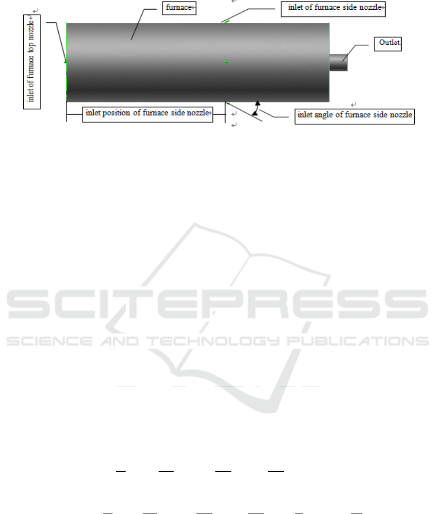
Figure1. physical model of numerical simulation calculation.
In this model, proper simplified treatment has been carried out for the actual gasifier. The small
rounded corners on the two ends of the furnace which have little impact on the flow field are
removed, and the gasifier is regarded as a cylinder, in which way the trouble and restrictions for the
model meshing are simplified, and at the same time the actual numerical simulation won’t be
impacted greatly. After confirmation of the physical model, mixed meshing will be carried out on
this model using tetrahedron and hexahedron.
2.2. The control equation of the continuous phase three-dimensional flow
In numerical simulation, the flow is described by the equation of mass, momentum and energy
conservation.
The general form of the continuity equation (mass conservation equation) [1] is:
0
z
w
y
v
x
u
t
(1)
The equation of motion of viscous fluid (momentum conservation equation) is N-S equation, and
its general form [2] is:
j
j
i
eff
ij
i
eff
i
i
i
x
u
xxx
u
x
f
Dt
Du
3
1
2
(2)
The control of turbulence kinetic energy in simulated calculation adopts viscous turbulent flow
model [3-5] of
. The general form of the governing equation which is expressed by tensor is as
follows:
G
xx
u
xt
j
effk
j
i
i
(3)
2
21
CGC
xx
u
xt
j
eff
j
i
i
(4)
In the formula:
represents the density of the mixture;
i
u
represents the velocity component of
the
i
direction;
t
means the time interval;
G
represents the turbulent kinetic energy caused by the
mean velocity gradient;
1
C
and
2
C
represents the empirical constants, and they are provided by
Cold State Numerical Simulation of New Type Coal-water-slurry Gasifier
347

literature [2], which are
1
C
= 1.42 and
2
C
=1.68, being used as the model constants; and
eff
is
the virtual viscosity here, being obtained by the following definition:
d
C
d
1
72.1
3
2
Among which
eff
;
100
C
; within high reynolds numbers,
2
C
, and in
which
0845.0
C
.
Adding definite condition to the above equations, the instantaneous solution of the fluid
movement in the flow field can be reached with the finite element method, including the velocity
distribution, pressure distribution, turbulence intensity distribution and other information of the fluid
motion[6-10].
3. Result of numerical simulation
3.1. The influence of the position of the nozzle inlet on the side of the furnace
In order to determine a appropriate location for the nozzle inlet on the furnace side, the author has
conducted numerical simulation of cold state for the flow field distribution, particle residence time,
particle concentration distribution and other aspects within the gasifier, with the condition when the
nozzle inlet respectively locates in the positions where the distances between the nozzle and the
furnace top take up 40%, 50% and 60% of the furnace height, which means the distance (h) between
the nozzle and the furnace top are 0.6m, 0.75m and 0.9m. Based on the result of the numerical
simulation calculation, the laws of the influence of the position of the nozzle inlet on the furnace side
on these factors have been analyzed and the optimal location for the nozzle inlet on the furnace side
have been obtained.
In the process of numerical simulation calculation, except for the change of the nozzle inlet
position, other working conditions are exactly the same, for which the details are: the angle of the
nozzle inlet on the side of the furnace is 45°; the spray angle of the various nozzles is 30°; the
velocity of the air flow near the nozzle outlet on the top of the furnace is 30 m/s; the velocity of the
air flow near the nozzle outlet on the side of the furnace is 25 m/s; the pulverized coal particles
entering the furnace are of the size of 100um~160um; the flow rate of the pulverized coal from the
nozzles on the top of the furnace is 10.8kg/h; the flow rate of the pulverized coal from each of the
nozzles on the side of the furnace is 2.7kg/h; and that the pulverized coal particles are injected into
the furnace from the various nozzles at the same time. The pulverized coal particles here only mean
the tracer particles, which are used to describe the concentration distribution of the particles in the
furnace and the retention time of the particles in the test furnace. During the numerical simulation
calculation, there will not be any chemical reaction occurred with the gas phase since they are inert
particles. The pressure in the gasifier is normal pressure in order to compare with the later tests. For
cold-state gasifier, the effect of the pressure in the furnace on the flow field distribution is very small.
Instead, the flow field distribution in the furnace is mainly affected by the furnace type of the gasifier,
the position and angle of the nozzle inlet, the velocity and kinetic energy of the nozzle inlet and the
nozzle flow. The pressure change in the gasifier is very small, being similar to a container with
constant pressure, that’s why when the numerical simulation is performed, normal pressure still can
well reflect the flow field distribution inside the gasifier under high pressure, and it will have no
impact on the model selection of gasifier.
IWEMSE 2018 - International Workshop on Environmental Management, Science and Engineering
348
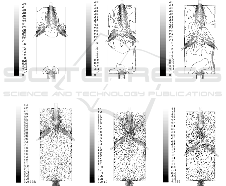
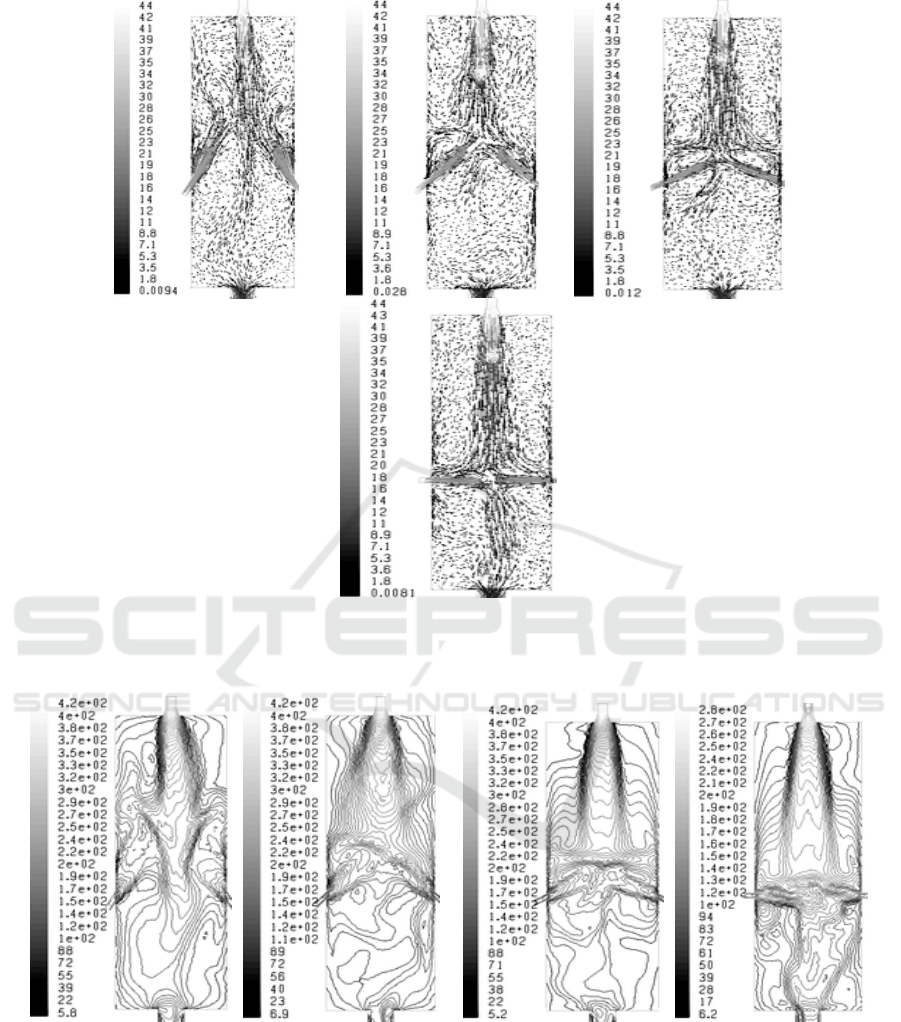
The following figure 2 and figure 3 are respectively the velocity distribution contour map and the
velocity distribution vector diagram of the internal furnace when the distances of the position of the
nozzle inlet to the top of the gasifier are 0.6m, 0.75m and 0.9m. As you can see from (1) in Figure 1
that when the distance of the nozzle inlet on the side of the furnace to the top of the gasifier is 0.6m,
the impact and the interception of the nozzle jet flow on the side of the furnace on the nozzle jet flow
on the top of the furnace is very little, in which way the function and advantage of the nozzle jet on
the side of the furnace cannot be achieved. In this case, the nozzle jet flow on the top of the furnace
passes through the middle of the nozzle jet flow on the side of the furnace before the strike of the
nozzle jet flow on the side of the furnace happens, and the nozzle jet flow on the side of the furnace
will be pushed to the side of the furnace wall by the main flow of the nozzle jet on the top of the
furnace; thus a scour of the furnace wall will exist. So, this kind of flow field distribution is very
unreasonable and the nozzle inlet on the side of the furnace cannot be located in this position.
(a)h=0.60m (b)h=0.75m c)h=0.90m
Figure 2.contours map of velocity distributing in coal-water-slurry gasifier.
(a)h=0.60m (b)h=0.75m c)h=0.90m
Figure 3.vectorgraph of velocity distributing in coal-water-slurry gasifier.
Cold State Numerical Simulation of New Type Coal-water-slurry Gasifier
349
(a)h=0.60m (b)h=0.75m c)h=0.90m
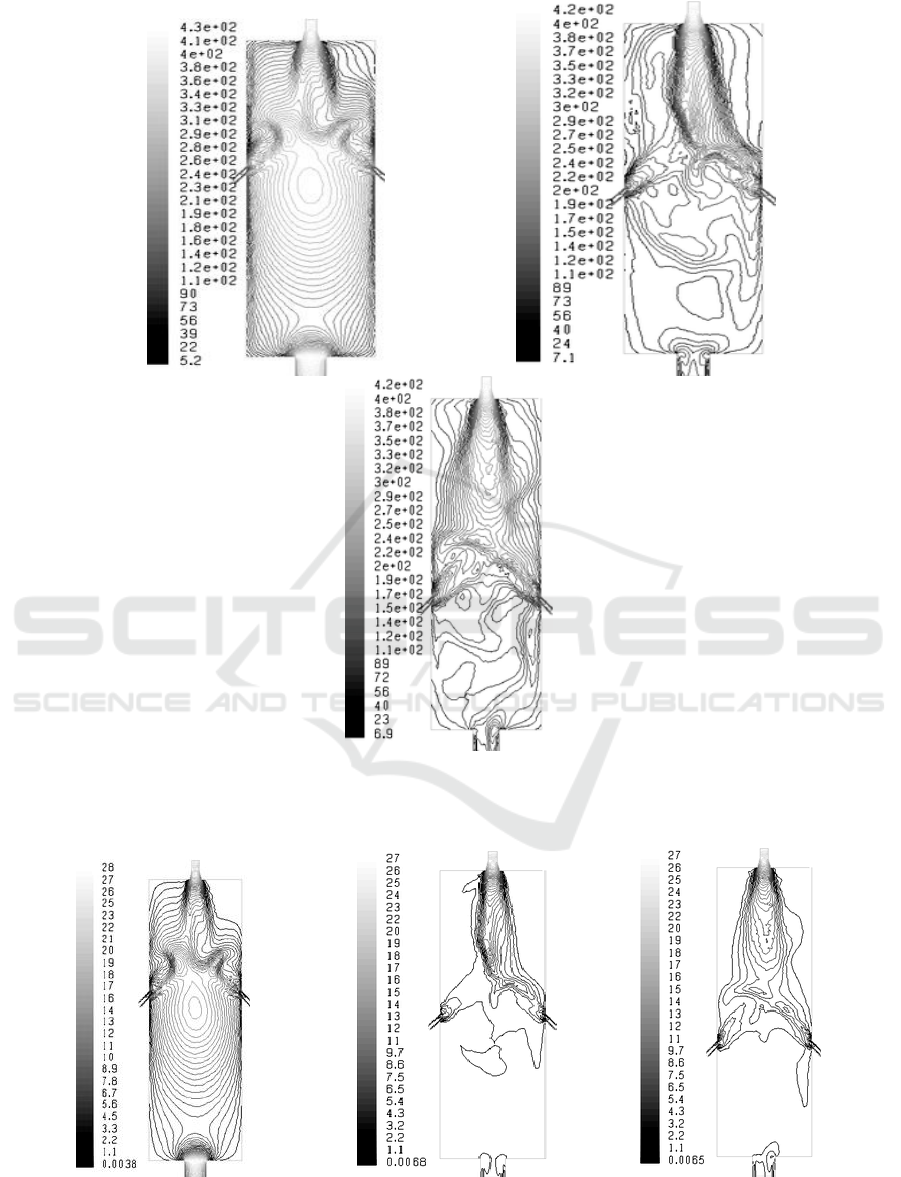
Figure 4.turbulence intensity distributing in coal-water-slurry gasifier.
(a)h=0.60m (b)h=0.75m c)h=0.90m
Figure 5.turbulence kinetic energy distributing in coal-water-slurry gasifier.
IWEMSE 2018 - International Workshop on Environmental Management, Science and Engineering
350

As you can see from (b) in Figure 2 and Figure 3 that when the distance of the nozzle inlet on the
side of the furnace to the top of the gasifier is 0.75m, the above undesirable phenomena weaken
evidently, the impact and interception of the nozzle jet flow on the side of the furnace on the main
flow of the nozzle jet on the top of the furnace become strong greatly, and the nozzle jet flow on the
side of the furnace dose not scour the wall of the furnace. However, the authors find out that the main
flow of the nozzle jet on the top of the furnace collides with the nozzle jet flow on the side of the
furnace without reaching the state of full development. In this way the jet flow from the various
nozzles will collide with each other after a very short time when they enter into the gasifier, which
will be disadvantageous for the nozzles to realize their sound atomization performance fully.
Meanwhile, when comparing (c) in Figure 2 and Figure 3, the recirculation zone formed around the
nozzle on the top of the furnace is relatively small because the distance of the nozzle inlet on the side
of the furnace to the top of the gasifier is very near. For gasifier of thermal operation, if the
recirculation zone around the nozzle on the top of the furnace is small, the volume of the air
entrainment of the surrounding high temperature gas by the nozzle jet flow on the top of the furnace
will be less, which is not good for the nozzle jet flow on the top of the furnace and the ignition and
burning in the collision area, and at the same time will reduce the stability of the ignition and
operation within the gasifier. So, the increase of the air entrainment of the surrounding high
temperature gas by the nozzle jet flow on the top of the furnace should be considered properly, for
which the most direct way is to increase the recirculation zone. When the distance of the nozzle inlet
on the side of the furnace to the top of the gasifier is 0.9m, the nozzle jet flow on the top of the
furnace collides with the nozzle jet flow on the side of the furnace when it’s fully developed. In this
way, the sound atomization performance of the nozzles on the top and both sides of the furnace can
be fully realized, and the time from the entering of the jet flow of the nozzle into the gasifier to the
collision is prolonged, which have provided precondition for the full development of jet flow,
increase the recirculation zone around the nozzle jet flow on the top of the furnace, strengthen the
nozzle jet flow on the top of the furnace, and increase the stability of the ignition and operation
within the gasifier. So, from the perspective of the distribution effect of the flow field, it’s
comparatively ideal when the distance of the nozzle inlet on the side of the furnace to the top of the
gasifier is 0.9m.
(a), (b), (c) in Figure 4 and Figure 5 are respectively the contour map of the turbulence intensity
distribution and turbulent kinetic energy distribution of the gasifier when the distances of the position
of the nozzle inlet to the top of the gasifier are 0.6m, 0.75m and 0.9m. As you can see from the
figures that when the distance is 0.6m, the turbulence intensity distribution and turbulent kinetic
energy distribution are apparently different from that of 0.75m and 0.9m. When the distance is 0.6m,
the nozzle jet flow on the side of the furnace dose not impact the internal flow field of the nozzle jet
flow on the top of the furnace; because the nozzle inlet on the side of the furnace is very near to the
top of the furnace, the position of the collision of the nozzle jet flow on the side of the furnace and on
the top of the furnace is just the position where the rigidity of the nozzle jet flow on the top of the
furnace are comparatively strong. In this case, the impact and interception effect of the nozzle jet
flow from the side on the jet flow from the top are not evident, and the kinetic energy of the flow
from the side of the furnace has been exhausted before it comes to intervene the internal flow field of
the nozzle jet flow on the top of the furnace, and thus the function of the nozzle jet flow on the side
of the furnace does not realize fully. However, the situation for the distances of 0.75m and 0.9m is
much better compared to 0.6. Especially when the distance of the nozzle inlet to the top of the
gasifier is 0.9, the kinetic energy of the flow from the side of the furnace are fully realized, the
impact and the interception of the nozzle jet flow on the top of the furnace are very evident, and the
area with comparatively intensified turbulent mixing strength becomes larger, all of which can be
seen from (c) in figure 4.9. So, from the perspective of the distribution of the turbulence intensity
distribution and turbulent kinetic energy distribution, it’s comparatively ideal when the distance of
Cold State Numerical Simulation of New Type Coal-water-slurry Gasifier
351
the nozzle inlet on the side of the furnace to the top of the gasifier is 0.9m, which is consistent to the
result author’ve got from the perspective of the flow field distribution.
3.2. Influence of nozzle inlet angle on the side of the furnace
After the position of the nozzle inlet on the side of the furnace is confirmed, the inlet angle becomes
another important parameter which will affect the distribution of flow field in the gasifier and the
particle concentration distribution. In order to find the proper angle, the numerical simulation
calculation for the internal flow field distribution, particle concentration distribution and average
residence time of the particles is carried out, with various inlet angles of 30°, 45°, 60°, and 90°.
(a)
=30° (b)
=45° (c)
=60° (d)
=90°
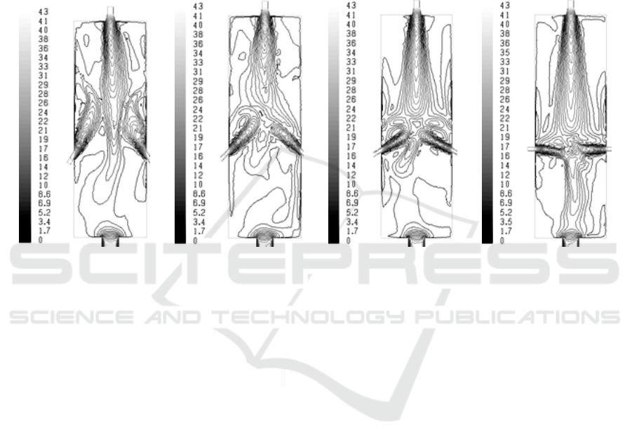
Figure 6.contours map of velocity distributing in coal-water-slurry gasifier.
During the calculation of numerical simulation, except for the changing of the nozzle angle on the
side of the furnace, other working conditions are completely consistent, the detailed conditions are:
the distance between the nozzle on the side of the furnace and the top of the furnace is 0.9m; the
atomizing angle of the various nozzles is 30˚; the air velocity of the nozzle outlet on the top of the
furnace is 30m/s; the air velocity of the nozzle outlet on the side of the furnace is 25m/s; the
pulverized coal particles coming into the furnace are with the size of 100um~160um; the flow rate of
the nozzle on the top of the furnace is 10.8kg/h; the flow rate of each of the nozzles on sides of the
furnace is 2.7kg/h, and the pulverized coal particles will be jetted into the furnace from the various
nozzles at the same time. The same as above, the pulverized coal particles are just tracer particles too,
which are used to describe the concentration distribution of particles in the furnace and their retention
time in the test furnace. In the process of the numerical simulation, no chemical reaction will occur
with the gas phase, since they belong to inert particles, and in order to compare with the later tests,
the pressure in the gasifier is under normal pressure.
IWEMSE 2018 - International Workshop on Environmental Management, Science and Engineering
352
(a)
=30° (b)
=45° (c)
=60° (d)
=90°
Figure 7.vectorgraph of velocity distributing in coal-water-slurry gasifier.
(a)
=30° (b)
=45° (c)
=60° (d)
=90°
Figure 8.turbulence intensity distributing in coal-water-slurry gasifier.
Cold State Numerical Simulation of New Type Coal-water-slurry Gasifier
353

(a)
=30° (b)
=45° (c)
=60° (d)
=90°
Figure 9. turbulence kinetic energy distributing in coal-water-slurry gasifier.
Diagrams of (a), (b), (c), and (d) in figure 6 and figure 7 are the velocity distribution contour map
and the velocity distribution vector diagram with the angles of the nozzle inlets on the side of the
furnace respectively being 30°, 45°, 60°, and 90°. As you can see from figure 6 (a) and figure 7 (a)
that when the angle is 30°, the impact and interception effect of the nozzle jet flow from the side of
the furnace on the main flow from the nozzles on the top is very little. The main flow from the
nozzles on the top of the furnace goes through the middle of the nozzle jet flow from the side of the
furnace, in which case the nozzle jet flow from the side of the furnace will be pushed to one side of
the furnace wall and the main jet flow from the nozzles on the top of the furnace will become long
and narrow. In the diagram, it shows clearly that the jet flow from the nozzles on the side of the
furnace is obviously bent to one side of the furnace wall in the later stage, and it has a serious scour
effect on the wall of the furnace; besides, the main jet flow on the top of the furnace rushes directly
to the bottom outlet of the furnace after going through the inter-space, which should be avoided all
the time in actual operation. So, from the perspective of the flow field analysis, it’s totally unsuitable
with the angle of the nozzle inlet on the side of the furnace being 30°. Compare the diagrams of (b),
(c), and (d) in figure 6 and figure 7, and you will find when the angle is 45°, the timing for collision
between the nozzle jet flow from the side of the furnace and the main nozzle jet flow from the top of
the furnace is the most appropriate, in which time the main jet flow is just fully developed when
colliding and both the nozzle jet flows from the side of the furnace and the main nozzle jet flow from
the top of the furnace are with a relatively higher speed and larger kinetic energy. In this case, the
turbulence mixing degree during the collision is higher, and the period before the collision is longer
compared to the angles of 60° and 90°. So the various flows from the sides of the furnace can be fully
developed, and the sound atomization performance of the various nozzles is fully realized. When the
angle of the nozzle inlet on the side of the furnace is 60° or 90°, since the time before the collision of
the nozzle jet flow from the side of the furnace and the main nozzle jet flow from the top of the
furnace is prolonged, the latter is reaching its decay phase, thus the collision will occur with a
relatively lower speed and the weaker kinetic energy. In this case, the turbulent mixing degree is not
very good when colliding; besides, the increase of the angle of the nozzle inlet on the side of the
furnace, the time between the entering of the jet flow from the various nozzles on the side of the
furnace and the collision will be less, which will result in the underdevelopment of the jet flow from
the nozzles on the side of the furnace when the collision happens and the sound atomization
performance of the nozzles on the side of the furnace will not be easy to be realized. At the same
time you can see that there is still scour on the inner wall of the furnace existing when the angle is
60° or 90°, which may cause severe scour and corrosion for the internal wall of the gasifier, and even
worse for the service life of the firebrick. Moreover, when the angle is 90°, the downward impact
IWEMSE 2018 - International Workshop on Environmental Management, Science and Engineering
354

flow caused by the mutual offset of the nozzles on both sides of the furnace will rush directly at the
bottom outlet of the gasifier, which greatly increases the possibility of "short circuit" phenomenon.
Comparing the various graphics,as you can see that the probability of the "short circuit" phenomenon
from big to small is happening in the following sequence: 90°> 30° > 60° > 45°. Based on all the
above analysis, the collision of the jet flow from the various nozzles on the side of the furnace is
having the best timing when the angle of the nozzle inlet is 45°, and the possibility of "short circuit"
phenomenon is comparatively smaller. So, from the result of the numerical simulation calculation,
the most ideal angle of the nozzle inlet is 45° under the various conditions.
Diagrams of (a), (b), (c), and (d) in figure 8 and figure 9 represent the turbulent intensity and
turbulent kinetic energy distribution of the gasifier with the angles of the nozzle inlet being 30°, 45°,
60°, and 90°. Seeing from the turbulent intensity distribution in figure 8, the nozzle jet flow on the
side of the furnace and the main nozzle jet flow from the top of the furnace will form a local
stagnation zone in the edge of the collision area no matter under what working condition. In the
stagnation zone, the turbulent mixing is in the least level, which is most evident when the angle of the
nozzle inlet on the side of the furnace is 30°; because when the angle is 30°, both the jet flow from
the top and the side of the furnace do not reach the state for fusion, thus the nozzle jet flow on the
side of the furnace will bent to the inner wall of the gasifier after its collision with the jet flow from
the nozzle on the top of the furnace, without reaching the internal of the main jet flow from the
nozzle on the top of the furnace. That’s why the mixing effect will be surely very poor. Hover when
the angle of the nozzle inlet on the side of the furnace is 90°, the collision mixing zone of the jet flow
from the nozzle on the top of the furnace and on the side of the furnace is not evident, and a turbulent
flow with a downward high turbulent strength is formed after the collision of the jet flow from the
nozzles on the side of the furnace, which will rush directly at the bottom outlet of the gasifier. In this
case, the possibility of "short circuit" phenomenon will surely increase. The turbulent intensity
distribution is comparatively much better when the angles are 45° and 60°, compared with angles of
30° and 90°, with a more intensified turbulent strength in the collision zone. When the angle is 45°,
the turbulent mixing degree in the flow field from the nozzle on the top of the furnace and in the
surrounding backflow zone is higher, and there isn’t any downward impinging stream with high
turbulent strength at the bottom of the flow field from the nozzles on the side of the furnace. Seeing
from the turbulent kinetic energy distribution in figure 9, when the angle is 45°, all the kinetic
energy of the nozzle jet flow from the side of the furnace is consumed on the collision with main jet
flow from the nozzles on the top of the furnace, in which case the impact and interception effect of
the nozzle jet flow on the side of the furnace is fully realized and the turbulence mixing effect of the
nozzle jet flow on the top of the furnace increases maximally. When the angle is 30°, the nozzle jet
flow on the top of the furnace cannot collide with the nozzle jet flow on the side of the furnace in a
sound way, thus a strong turbulent mixing effect does not come into being. Most of the kinetic
energy of the nozzle jet flow from the top of the furnace is consumed on pushing the jet flow of itself,
thus the main jet flow from the nozzles on the top of the furnace directly rush at the bottom outlet of
the furnace. Similar to this, when the angle is 90°, even the jet flow from the nozzles on the top of the
furnace is ll intercepted into the upper- and middle-part within the furnace, part of the collision flow
with larger kinetic energy rushes into the bottom of the furnace after the collision. The formation of
the downward impact flow can be clearly seen from the distribution of turbulent kinetic energy in the
furnace. The turbulent kinetic energy distribution in the furnace is much better when the angle is 60°
compared to the situation when the angles are 30° and 90°, but kind of worse when compared to the
situation when the angle is 45°. So, from the perspective of the effects of turbulent kinetic energy and
turbulence intensity distribution, it’s most ideal when the angle is 45°, in which point the distribution
of flow field in the gasifier is the best, and this is consistent to the result have got earlier.
Cold State Numerical Simulation of New Type Coal-water-slurry Gasifier
355

4. Conclusions
In this thesis, numerical simulation calculation research is carried out for
the cold aerodynamical field, turbulence intensity and turbulent kinetic energy distribution in the
new-type coal-water-slurry gasifier under conditions of different positions and angles of the nozzle
inlet on the side of the furnace, from which the optimum position of the nozzle inlet on the side of the
furnace and the optimum angle of the nozzle inlet on the side of the furnace are reached under the
simulated working condition. The result can provide empirical data and theoretical reference for the
model selection and the confirmation of the specific parameters. After the simulation, the author
carries out verification for the result of the numerical simulation calculation with experiments (the
details will not be discussed here because of the limited length of the paper), from which the
experiment data and the numerical simulation calculation results coincide ll. This shows that this
numerical simulation calculation research is feasible. The major conclusions are:
1) Establish the physical and mathematical model of the cold-state numerical simulation for the
flow field distribution in the gasifier, and after verification, it shows that these models are
right and feasible.
2) Numerical simulation calculation is carried out for the flow field distribution, turbulence
intensity and turbulent kinetic energy distribution in the new-type coal-water-slurry gasifier
under conditions of different positions of the nozzle inlet on the side of the furnace, and
according to the result of the simulation, it shows that the flow field distribution, turbulence
intensity and turbulent kinetic energy distribution within the gasifier is most reasonable when
the distance of the nozzle inlet on the side of the furnace to the top of the gasifier is 0.9m,
with the particle concentration distribution being the evenest and the time of the mean
detention time of the particles in the gasifier being the longest. So the position of the nozzle
inlet on the side of the furnace is the most ideal with the distance of 0.9m from the nozzle to
the top of the gasifier.
3) Numerical simulation calculation is carried out for the flow field distribution, turbulence
intensity and turbulent kinetic energy distribution under conditions of different angles of the
nozzle inlet on the side of the furnace, and according to the result of the simulation, it shows
that the flow field distribution, turbulence intensity and turbulent kinetic energy distribution
within the gasifier is most reasonable when the angle of the nozzle inlet on the side of the
furnace is 45°.
Acknowledgment
This work was supported by Henan Province natural science foundation project (Grant No.
182300410133)
References
[1] Fei X L 1995 Advanced hydromechanics Xi an: Xi an Jiaotong University publishing company
530-540
[2] Choudhury D 1993 Introduction to the Renormalization Group Method and Turbulence
Modeling Fluent Inc. Technical Memorandum TM-107
[3] Morsi S A and Alexander A J 1972 An Investigation of Particle Trajectories in Two-Phase
Flow Systems J. Fluid Mech. 55(2):193-208
[4] Haider A and Levenspiel O 1989 Drag Coefficient and Terminal Velocity of Spherical and
Nonspherical Particles. Powder Technology, ,(58):63-70
[5] Ounis H, Ahmadi G and McLaughlin J B 1991 Brownian Diffusion of Submicrometer Particles in
the Viscous Sublayer Journal of Colloid and Interface Science 143(1):266-277
[6] Yu H L, Zhao X, Zhou Z J and et al 2004 Numerical Simulation Analysis on The Effects of
O/C Ratio and Coal Concentration in Coal Water Slurry on Gasification Process Journal of
IWEMSE 2018 - International Workshop on Environmental Management, Science and Engineering
356

Fuel Chemistry and Technology 32(4):370-374
[7] Yu H L, Zhao X, Zhou Z J and et al 2004 Numerical Simulation of Effect of Oxygen Coal
Mole Ratio on Coal Water Slurry Gasification Process Journal of China Coal Society
29(5):606-610
[8] Yu H L, Liu J Z, Fan X and et al 2005 Experimental Study of Atomizing performance of a
New Type Nozzle for Coal Water Slurry Journal of Shanghai Institute of Electric Por.
25(22): 99-103
[9] Yu H L, Liu J Z, Fan X and et al Experimental Study of Atomizing performance of a New
Type Nozzle for Coal Water Slurry-Ⅱ Journal of Shanghai Institute of Electric
Po.r(already be employed)
[10] Yu H L, Zhao X, Zhou Z J and et al 2005 Numerical Simulation of coal-water-slurry
Concentration Effect on coal-water-slurry gasification Process Chinese Journal of Por
Engineering 25(2):217-220,238
Cold State Numerical Simulation of New Type Coal-water-slurry Gasifier
357
