
Comparison Study of Structural Strength between Longitudinal and
Transverse Modulus on The Hatch Cover using Finite Element
Method
Dony Setyawan
1
, Septia Hardy Sujiatanti
1
and Novario Pratama Adiguna
1
1
Department of Naval Architecture, Faculty of Marine Technology, Institut Teknologi Sepuluh Nopember, Surabaya,
Indonesia
Keywords: The Longitudinal Modulus, Transverse Modulus, FEM.
Abstract: Container ship carries cargo that mostly container, so cargo hold be designed with the large enough
hatchway to making easy loading and unloading container. Owners usually want to optimize space on cargo
hold. Optimizing space on cargo hold means that if cargo hold is fully loaded by the container, the owner
can still put the container above hatch cover. There are 2 construction members which influence hatch cover
strength, longitudinal & transverse. Finite element method is used to compare strength between longitudinal
& transverse of the hatch cover. The analysis was performed by changing ± 10% & ± 20% longitudinal
modulus and transverse modulus of the model hatch cover. As a result, due to increase 20% longitudinal
modulus, stress is reduced -9.903%, while adding 20% transversal modulus only reduces -5.31% stress.
Reducing 20% longitudinal modulus increase 5.47% stress, while reducing 20% transversal modulus only
increases 4.94% stress. According to the analysis result, it can be inferred that changing the longitudinal
modulus is more influential than changing transversal modulus. e
1 INTRODUCTION
The function of hatch cover on container ships
generally has the same working system and function,
which is used to cover the part of the hatch on the
container ship. However, what distinguishes
between hatch cover on cargo ships and container
ships is that container ships carry commonly called
containers, so container ship must have a wide hatch
for loading space. Owners usually want to optimize
space on cargo hold. Optimizing space on cargo hold
means that if cargo hold is fully loaded by the
container, the owner can still put the container above
hatch cover (Keith, 2001). Hatch cover must have
enough strength to hold the load from the container.
Previous study an analysis was carried out by
comparing 3 variations of hatch cover model. The
first model hatch cover is divided into 3 transverse
partitions. Second model hatch covers without
partition. The third model hatch cover is divided into
5 longitudinal partitions. From three types of hatch
cover, model hatch cover 3 transverse partition is the
most effective model (Fikri and Kurniawati, 2016).
In this comparison study between longitudinal &
transverse construction, most affect construction to
hatch cover stress will be searched with 3 transverse
partitions as a model. The analysis is performed by
changing the longitudinal modulus and transverse
modulus of the hatch cover. From the comparison of
the stress result, the construct will be obtained which
is the most influential to the hatch cover
2 LITERATURE REVIEWS
Hatch cover is a very important equipment in the
ship, which construction and mechanism must
follow Classification rules and International Load
Line Convention (ILLC) 1966. The purpose of the
hatch cover and hatch coaming are to prevent water
from entering through the opening (loading) of the
loading space on the ship deck.
One type of hatch cover is a lift-away hatch
cover (Fikri and Kurniawati, 2016). Hatch cover
using pontoon or lift away hatch cover makes it
easier for the loading and unloading system. Hatch
cover type Lift away hatch cover is good for ships
Setyawan, D., Sujiatanti, S. and Adiguna, N.
Comparison Study of Structural Strength between Longitudinal and Transverse Modulus on The Hatch Cover using Finite Element Method.
DOI: 10.5220/0008375300970100
In Proceedings of the 6th International Seminar on Ocean and Coastal Engineering, Environmental and Natural Disaster Management (ISOCEEN 2018), pages 97-100
ISBN: 978-989-758-455-8
Copyright
c
2020 by SCITEPRESS – Science and Technology Publications, Lda. All rights reserved
97
that have multilevel goods (Dewangga and Yulianto,
2012).
Figure 1: Lift-Away Hatch Cover.
2.1 Finite Element Method
Von misses stress is stress that obtained through
calculations involving strains in all axes (x, y, and z)
(Rabbani, et.al, 2017). The theory of the collapse of
von misses yield criterion is used in this study as a
reference in the analysis of stress used. The
following equation for von misses:
(1)
Where,
σx = x-axes stress
σy = y-axes stress
σz = z-axes stress
σ’ = equivalent von misses stress
Finite element method is a numerical calculation
technique that results obtained is the value of the
approach of the actual results. As the size of the
element decreases, the results obtained will be
different and sequential. The calculation approach
will produce a convergent value with the actual
results when the mesh quality is added and the
elements are formed more and smaller in size (Biro
Klasifikasi Indonesia, 2016).
2.2 Hatch Cover Conversion
Hatch cover is considered to have sufficient strength
if the stress value that occurs in each structure does
not exceed the value of equivalent stress σv given by
ship classification for the minimum hatch cover
(Pramono, et.al, 2016).
(2)
Where,
σv = equivalent stress hatch cover
ReH = minimum nominal upper yield point, 235
N/mm²
Model for this research requires modulus
conversion to get the variation. To find the modulus
can be found by the moment inertia calculation
tabulation which will be divided by the value of the
neutral axis point.
3 METHODOLOGY
In this study, the effectiveness between the
longitudinal and the transversal will be compared.
The analysis is carried out by changing the modulus
of the transverse and longitudinal support of ± 10%
& ± 20%. The next step is modelling. The hatch
cover model is drawn from the deck to the hatch
cover. After modeling, the next step is element
convergence. After obtaining the converging
element size of each model, the model is given a
load and boundary conditions. Stress must be
checked with stress permission from BKI based on
formula (2). Finally, effective construction can be
determined.
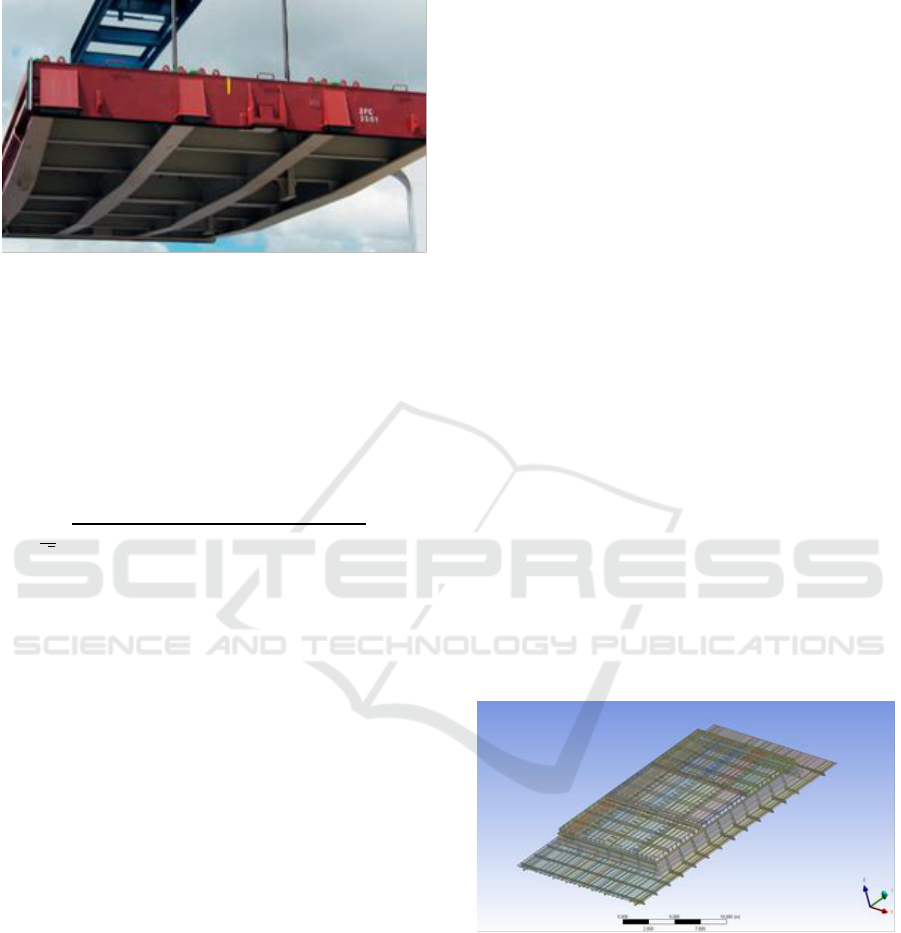
3.1 Finite Element Modeling
Finite element models are made from ship decks to
hatch cover. Because the model is complex, then
modeling of hatch cover using CAD (Computer-
Aided Design) assist software.
Figure 2: Geometric Model.
Locking and damping systems are not modeled.
The locking system requires a very detailed model
which can cause an error model. For locking system
modelling and damping systems, it is carried out in
accordance with Figure 3.
ISOCEEN 2018 - 6th International Seminar on Ocean and Coastal Engineering, Environmental and Natural Disaster Management
98

Figure 3: Locking and Damping System.
Meshing is a process of finite elements to divide
the whole system into smaller elements to obtain a
detailed analysis of the entire system. In this study,
the element types used are solid elements of
Tetrahedron and Hex Dominant because there are
parts of construction that are simple and
complicated, in addition to the geometry modeling
has been given thickness. Solid elements have
quadratic displacement properties and good for
modeling irregular mesh shapes.
Figure 4: Finite Element Model.
Variation of the model is given to compare the
analysis results and get the most effective
construction (longitudinal or transversal). The
analysis is carried out by comparing the construction
hatch cover model as shown in Table 1.
Table 1: Variation of Hatch Cover Model.
Constructi
on
Initial Profile
Modulus
Change
Profil after
Change
Longitudin
al
L 100x100x10
+20%
L 100x100x12
+10%
L 100x100x11
-10%
L 100x9+90x10
-20%
L 100x8+100x9
Transversa
l
T 450x9 +
100x10
+20%
T 450x11 +
100x11
+10%
T 450x10 +
100x11
-10%
T 450x8 +
125x8
-20%
T 450x8 +
125x7
3.2 Loading and Boundary Condition
The type of load applied is a force, which is a static
load on the legs of the container. The amount of the
load is affected by the type of container weight and
container tier placed on the hatch cover. In this case,
containers use BAY 13 where the hatch cover
transports a maximum of 3 tier containers with a
maximum load of 38 tons. The load used is a force
by multiplying gravity becomes 372.4 kN. The
container feet are 4 so that the weight of 372.4 kN is
distributed on 4 feet of the container, 1 container
foot gets a load of 93.1 kN.
Figure 5: Load Distribution.
The parts that are given a support are the ends of
the deck and the deck part that is welded with the
bulkhead. This is done because geometry modeling
for analysis is carried out only on the deck until the
hatch cover.
Table 2: Applied Boundary Condition.
Axis
Displacement
Rotation
X
0
Free
Y
0
Free
Z
0
Free
4 RESULT AND DISCUSSION
Longitudinal and transverse effectiveness are tested
with the hatch cover model according to the data.
The tests are carried out by reviewing the von misses
model voltage due to changes in modulus of the
transverse and longitudinal.
Comparison Study of Structural Strength between Longitudinal and Transverse Modulus on The Hatch Cover using Finite Element Method
99

5 CONCLUSIONS
According to the analysis and results, this research
can be concluded that longitudinal construction is
more influential than transverse construction
because of a load of containers. Container load on
the hatch cover is symmetrical so that torque loads
are not too significant. So that transverse
construction has no major effect, while construction
has a big influence.
REFERENCES
Biro Klasifikasi Indonesia, Rules for The Classification
and Construction of Seagoing Steel Ships, Indonesia:
BKI (2016).
D.R. Pramono, A. Imron & M.N. Misbah, Analyze the
Strength of the Lengthening of the Floating Dock
Conversion from the Barge to the Finite Element
Method, Surabaya: Jurnal Teknik ITS Vol. 5, No. 2.
ISSN: 2337-3539, Surabaya: ITS (2016)
D.V. Dewangga & T. Yulianto, Analysis of the Effect of
Flange Angle, Toe Radius, and Preparation Angle on
Deformation and Residual Voltage on Welding Butt
Joint with Double V Campaign Using Finite Element
Method, Jurnal Teknik ITS Vol. 1, ISSN: 2301-9271,
Surabaya: ITS (2012).
International Load Line Convention, International
Maritime Organization, London (1966).
M.U. Fikri & H.A. Kurniawati, Design Livestock Carrier
Makassar - Jakarta Route To Supply Cattle Needs in
Jakarta and Surroundings, Jurnal Teknik ITS Vol. 5.
No. 2. ISSN: 2337-3539, Surabaya: ITS (2016).
T. Keith, Hold and Hatch Cover, London: A.Bilbrough &
Co.Ltd (2001).
Z. Rabbani, A. Zubaydi & S.H. Sujiatanti, Analisa
Kekuatan Sekat Bergelombang Kapal Tanker
Menggunakan Metode Elemen Hingga, Surabaya:
Jurnal Teknik ITS 6 (2), G282-G287, ISSN: 2337-
3520, Surabaya: ITS, (2017).
ISOCEEN 2018 - 6th International Seminar on Ocean and Coastal Engineering, Environmental and Natural Disaster Management
100
