
Stress Analysis of Helideck Structures on Offshore Patrol Vessel
Achmad Zubaydi
1
, Septia Hardy Sujiatanti
1
and Refdi
1
1
Department of Naval Architecture, Faculty of Marine Technology, Institut Teknologi Sepuluh Nopember, Surabaya,
Indonesia
Keywords: Helideck, Offshore Patrol Vessel
Abstract: The helicopter deck structure plan should be able to guarantee a structure with a stress not exceeding the
permissible stress. A helideck structure analysis is carried out based on the loading conditions obtained from
helicopter landing variations to calculate maximum load, maximum stress, and deformation. The results
obtained are von misses stress and deformation values for various loading condition. The maximum stress
generated under condition 1 is 109 MPa with a deformation value of 2.015 mm. The maximum value of the
maximum stress for condition 2 is 135 MPa with a deformation value of 2,069 mm. The maximum value of
the maximum stress for condition 3 is 174 MPa with a deformation value of 4,161 mm. The maximum value
of the maximum stress for condition 4 is 223 MPa with a deformation value of 5,969 mm. It can be concluded
that condition 1 is the most optimum helicopter landing conditions with the lowest stress and deformation
among all load conditions.
1 INTRODUCTION
Republic of Indonesia Marine Security Agency
(BAKAMLA RI) requires a large and sophisticated
fleet of patrol boats to defend the Indonesian border.
One of the sophistication is helideck for global
monitoring. The helideck construction planning is to
make a construction that has a stress level at the limits
permitted. Planning a helideck construction must be
able to guarantee a structure with a stress no more
than the clearance stress. Helideck construction must
be designed to avoid excessive elastic deformation
which can result in changes in geometry due to the
load received. These parts must be measured
appropriately for the actual or charged styles.
To ensure the helideck can be used safely and
function properly, it is necessary to conduct research
as an effort to identify any hazards that might
threaten, the main purpose is to verify the strength of
the helideck structure when subjected to a load with
the condition of the helicopter remaining on the
runway and landing. The design of the helideck must
be able to anticipate the occurrence of emergency
landings by helicopters. Emergency landings can be
located around the helideck area, inside or outside the
helipad.
This research was conducted to calculate the
maximum loading value, maximum stress,
deformation by using finite element method.
Calculating the level of security in the helideck
construction, calculating the level of safety (safety
factor) in the construction of the helideck and
knowing the most critical components and need to get
more attention.
2 LITERATURE REVIEWS
Helicopter deck known as helideck is a landing area
for specially built helicopters on ships including all
structures, firefighting equipment and other facilities
needed for safe operation of helicopters. Other
facilities include refueling facilities and hangar
facilities. Helicopter landing areas must be designed
for emergency helicopter landings. The helicopter
landing area must be on the topmost deck and have a
large manouver zone, and most importantly the
helicopter landing area must be close to the side of the
ship.
Helideck is a deck of a ship or an offshore
structure built for landing or taking off a helicopter as
shown in Figure 1. Landing areas must have the
widest possible area to provide safe access to
helicopters upon landing (DNV, 2010).
106
Zubaydi, A., Sujiatanti, S. and Refdi, .
Stress Analysis of Helideck Structures on Offshore Patrol Vessel.
DOI: 10.5220/0008375501060110
In Proceedings of the 6th International Seminar on Ocean and Coastal Engineering, Environmental and Natural Disaster Management (ISOCEEN 2018), pages 106-110
ISBN: 978-989-758-455-8
Copyright
c
2020 by SCITEPRESS – Science and Technology Publications, Lda. All rights reserved
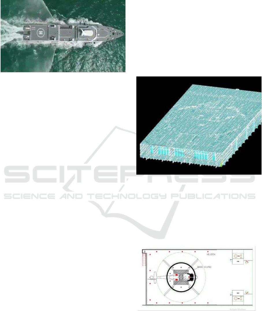
Figure 1: Helideck on the Bakamla 110 m
The helipad is a landing area for helicopters. A
helipad is made by hardening a surface away from
obstacles so that the helicopter can land. The helipad
is generally constructed of concrete and is marked by
a circle or a letter "H" to be visible from the air. Some
factor considered in planning a helipad, including
namely the type of helicopter that involves the weight
of the helicopter with full fuel and rotor diameter,
environmental conditions, and signs designed for
visual pilot (Sutehno, 2014).
Von Mises stress is a combination of all stress
components, which consist of normal stress on three
axes, and shear stresses, which react at certain places.
Von misses stress is suitable for the ductile material.
The stress chosen in this analysis is von Mises stress.
Von Mises stress is used to predict the material
elongation on certain loading conditions (Sanjaya,
et.al, 2017).
The von misses stress that produces a value above
the material yield strength, the material will provide
a power response equal to the value of the yield
strength of the material itself. If the von misses stress
produces a value exceeding ultimate strength, the
material will break (Hoque, 2013).
3 METHODOLOGY
3.1 Finite element modelling
Helideck modelling is made using finite element
software. The finite element model must be made in
order to represent the actual conditions so that the
analysis process can provide results that are in
accordance with the conditions experienced by the
structure.
The pre-processor is the initial stage in the process
of structural analysis where data model preparation is
done and in this process, the structure is divided into
finite small elements called mesh making. Then the
boundary conditions are applied to the structure
which has been divided into small elements
(meshing) to determine the degree of freedom of the
structure analyzed. Calculation phase in the process
of structural analysis. The boundary and load
conditions that have been applied to the model will be
calculated using the finite element equation.
The post-processor is the last stage of structural
analysis that displays the output of the calculation can
be the solver stage into the graphic form according to
the interpretation chosen. The finite element model of
helideck as shown in Figure 2.
Figure 2: Finite element model of helideck
3.2 Loading Condition
The variation in this study is a different landing on the
loading location given to the helideck model that is
made. Variations in the landing location needed to
analyze landings that may occur. For each specific
helideck loading, there are 4 types as shown in Figure
3 to Figure 6.
Figure 3: Helicopter position on loading condition 1
Stress Analysis of Helideck Structures on Offshore Patrol Vessel
107
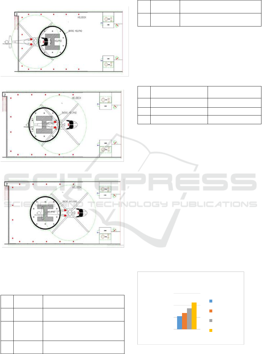
Figure 4: Helicopter position on loading condition 2
Figure 5: Helicopter position on loading condition 3
Figure 6: Helicopter position on loading condition 4
Resume of the loading condition as shown in
Table 1.
Table 1: Loading condition on the helideck structure
No
Load
Conditions
Explanation
1
Condition
1
All wheels are in the helipad circle
2
Condition
2
One wheel (front wheel) is inside
the helipad circle, two wheels (rear
wheel) are outside the helipad circle
3
Condition
3
Two wheels (rear wheel) are inside
the helipad circle, two wheels (front
wheels) are outside the helipad
circle
4
Condition
4
All wheels are outside the helipad
circle
To perform a strength analysis using finite
element software, the load experienced by the
structure must be applied to the model. Loading must
be applied according to the conditions experienced by
the structure. Loading uses a static load due to the
load which is a helicopter load. The load applied to
the helideck can be seen in Table 2.
Table 2: The load applied on the helideck
No
Load Type
Load Value
1
Landing force
57.330 kN
2
Wind load
64.479 kN
3
Enviromental loads
0.5 kN/m
2
The load is applied to the model in the form of
pressure on the helicopter wheel area. Landing force
loading is distributed to each helicopter wheel. For
wind load loading distributed in areas that get wind
pressure caused by the rotation of the helicopter
blades. Environmental loads are distributed in the
helipad area.
4 Result and discussion
4.1 Maximum stress
According to the results of the helideck model
simulation, the maximum stress values that occur in
each variation of the helideck model are obtained.
The stress chosen in this analysis is von misses the
stress. Von Mises stress is used to predict the level of
material elongation on certain loading conditions.
The maximum stress value on the entire model can be
seen in Figure 7 and Table 3.
Figure 7: Maximum stress for various loading
condition on the entire model
0
100
200
300
Maximum Stress
(MPa)
Load variation
Maximum Stress
Condition 1
Condition 2
Condition 3
Condition 4
ISOCEEN 2018 - 6th International Seminar on Ocean and Coastal Engineering, Environmental and Natural Disaster Management
108

Figure 7 shows that the stress model condition 1
has a stress value of 109 MPa. In condition 2, the
maximum stress value is 135 MPa. In condition 3 the
maximum stress value is 174 MPa. The maximum
stress in condition 4 is 223 MPa. Resume of
maximum stress is given in Table 3.
Table 3: The load applied on the helideck
No
Load Variation
Maximum Stress (MPa)
1
Condition 1
109
2
Condition 2
135
3
Condition 3
174
4
Condition 4
223
The maximum stress must be compared to the
price of the stress permitted by regulation. According
to BKI regulations (2017), the determination of
permissible stress is divided according to the related
structure.
4.2 Maximum stress on the stiffeners
Figure 8 shows that all conditions produce stress
stiffeners under stress permits for stiffeners. First
condition experienced a maximum stiffeners stress of
15.27 MPa. In the second condition, the maximum
stiffeners increased to 36.86 MPa. In condition 3, the
maximum stiffeners decreased to 24.26 MPa. In
condition 4 experienced a maximum stiffeners stress
of 49.25 MPa. It can be stated that all four conditions
have met the maximum standard of permit stress on
stiffeners.
Figure 8: Maximum stress for various loading condition at
the stiffener
Resume of the maximum stress on the stiffeners for
the various condition is given in Table 4.
Table 4. Maximum stress for various loading
condition at the stiffener
Load
Variation
max
(MPa)
perm
(MPa)
max
≤
perm
Condition 1
15.27
213.63
Accepted
Condition 2
36.86
213.63
Accepted
Condition 3
24.26
213.63
Accepted
Condition 4
49.25
213.63
Accepted
4.3 Maximum stress on the main
girder
Figure 9 produces the main girder stress under the
main girder clearance stress. In condition 1, the
maximum stress of the main girder is 99.86 MPa. In
condition 2, the maximum stress of the main girder is
109 MPa. In condition 3 the maximum number of
main girders is 130 MPa. In condition 4, the
maximum value of the main gear between the three
other models is 140.8 MPa.
Figure 9: Maximum stress for various loading
condition at the main girder
Resume of the maximum stress on the main girder for
the various condition is given in Table 5.
Table 5: Maximum stress for various loading
condition at the main girder
Load
Variation
max
(MPa)
perm
(MPa)
max
≤
perm
Condition 1
99.38
162.069
Accepted
Condition 2
109.00
162.069
Accepted
Condition 3
130.00
162.069
Accepted
Condition 4
140.80
162.069
Accepted
4.4 Maximum deformation
Figure 10 shows the results of the maximum
deformation that occurs in the model for each
condition. In condition 1, the maximum deformation
value is 2.015 mm. In condition 2, the maximum
0
20
40
60
Maximum Stress
Stiffeners
(MPa)
Load variation
Maximum Stress Stiffeners
Condition 1
Condition 2
Condition 3
Condition 4
0
50
100
150
Maximum Stress Main
Girder
(MPa)
Load Variation
Maximum Stress Main
Girder
Condition 1
Condition 2
Condition 3
Condition 4
Stress Analysis of Helideck Structures on Offshore Patrol Vessel
109

deformation value increases to 2.069 mm. In
condition 3, the maximum deformation value
increased to 4.161 mm. In condition 4 has the largest
maximum deformation value among the three other
conditions which is 5.969 mm.
Figure 10: Maximum deformation for various
loading condition on the entire model
Resume of the maximum deformation for the
various condition is given in Table 6.
Table 6: Maximum deformation for various loading
condition on the entire model
No
Load Variation
Maximum deformation
(mm)
1
Condition 1
2.015
2
Condition 2
2.069
3
Condition 3
4.161
4
Condition 4
5.969
5 CONCLUSION
According to the analysis and results, this research
can be concluded as follows:
1. Highest maximum stress occurs in condition 4
with a maximum stress value of 223 MPa. The
smallest maximum stress value occurs in
condition 1 with a maximum stress value of 109
MPa,
2. All conditions reach maximum stress on each
component of the structure under the permit stress
of the structural component,
3. The deformation value is directly proportional to
the maximum stress value, the maximum
deformation value occurs in condition 4 which is
5,969 mm. The smallest maximum deformation
value occurs in condition 1 which is 2,015 mm,
4. The most optimum condition used by helicopter
landing is condition 1 by considering the value of
the smallest maximum stress and the smallest
maximum deformation
REFERENCES
DNV, 2010. Rules for classification of Ships-New
buildings-Special Equipment and Systems.
D. D. Sanjaya, S. H. Sujiatanti, T. Yulianto, 2017.
Jurnal Teknik ITS 6 (2), G277-G281, ISSN 2337-
3539.
K. Hoque., 2013. Analysis of Structural
Discontinuities in Ship Hull Using Finite Element
Method, Bangladesh.
W. Sutehno, 2014. Jurnal Teknik Sipil dan
Lingkungan Universitas Sriwijaya.
0
2
4
6
8
Maximum Deformation
(mm)
Load Variation
Maximum Deformation
Condition 1
Condition 2
Condition 3
Condition 4
ISOCEEN 2018 - 6th International Seminar on Ocean and Coastal Engineering, Environmental and Natural Disaster Management
110
