
The Simple Open Free Running Test for the Evaluation of Turning
Ship Ability
Aries Sulisetyono
Department of Naval Architecture, Institut Teknologi Sepuluh Nopember, Surabaya, Indonesia
Keywords: Ship Manoeuvring, Open Free Running Test, Image Processing.
Abstract: The ship manoeuvring test using an approach of the free running model on the open water pool is described.
In this test, the most important part is to retrieve a trajectory data of the model ship while it does
manoeuvre. It is necessary to have an accurate technique of the data retrieval during the test. A technique of
image processing is proposed in this paper with the aim to analyse the ship manoeuvring path. In this
method, the manoeuvring test of the model is recorded with the camera, and the movie result is then
analysed with the movie maker software to get the trajectory points for a second step. The 6500 DWT
tanker with a 1:85 scale model is tested on the turning test with the two different type of rudder namely the
conventional and the single flap. The test results are obtained in terms of parameters including advances,
transverse, tactical diameter and turning radius. The comparison results show the ship with single flap give
better the manoeuvring performance with reducing turning diameter about 13.04% and 14.5% for the
turning of Portside and Starboard respectively.
1 INTRODUCTION
The manoeuvrability of a ship is fulfilled to avoid
the accidents of ship collision in open or restricted
water areas. The IMO (International Maritime
Organization) released the Standards for ship
manoeuvrability for all ships that are operated in the
sea. In the early step design of the ship, the ship
manoeuvrability is predicted by using the approach
of the experimental and numerical method. The free
running model test is developed for testing of the
ship manoeuvring. This experimental technique is
more efficient and practical since it considers to
follow the requirements of ITTC (25rd ITTC
Manoeuvring Commission Report 2008). The model
test is equipped with its own propeller and rudder on
the scale in which the model is controlled by the
operator through the wireless communication
system.
The ship manoeuvrability basically depends on
controllability the rudder performance and the ship
speed. The rudder is designed to get a maximum
value of side force to be able to change any
directions of the ship’s hull. In this paper, the single
flap rudder is developed to improve the performance
of ship manoeuvrability with increasing the side
force (Watson and Tupper, 2001); Lewis and
Edwards, 1989). The foil of NACA 0018 series is
selected refer to (Sulisetyono, 2014; Sulisetyono and
Nasirudin, 2010, 2014) with about 30% addition flap
of the rudder area. The turning manoeuvrability is
considered with four parameters as the results of test
such as advance, transverse, tactical diameter, and
turning diameter. The image processing technique is
proposed to analyse the turning path of the model
ship while it tested at the certain speed for the two
design cases of the rudders.
2 METHODOLOGY
The ship model is a 6500 DWT tanker with the main
dimensions such as Length of water line (Lwl) 120
m, Breadth (B) 22.1 m, Draft (T) 7.12 m,
Longitudinal centre of buoyancy (LCB) 58.7 cm
(from FP), and Coefficient block (Cb) 0.773. The
model with the scale of 1:85 is shown in Figure 1.
The turning test is conducted on the pool which
has enough width to avoid the blockage effect, is the
public swimming pool with the dimension of 12 m
length, 6 m breadth, and 1.5 m depth. The ship
models are equipped with including an AC motor, a
116
Sulisetyono, A.
The Simple Open Free Running Test for the Evaluation of Turning Ship Ability.
DOI: 10.5220/0008375901160119
In Proceedings of the 6th International Seminar on Ocean and Coastal Engineering, Environmental and Natural Disaster Management (ISOCEEN 2018), pages 116-119
ISBN: 978-989-758-455-8
Copyright
c
2020 by SCITEPRESS – Science and Technology Publications, Lda. All rights reserved
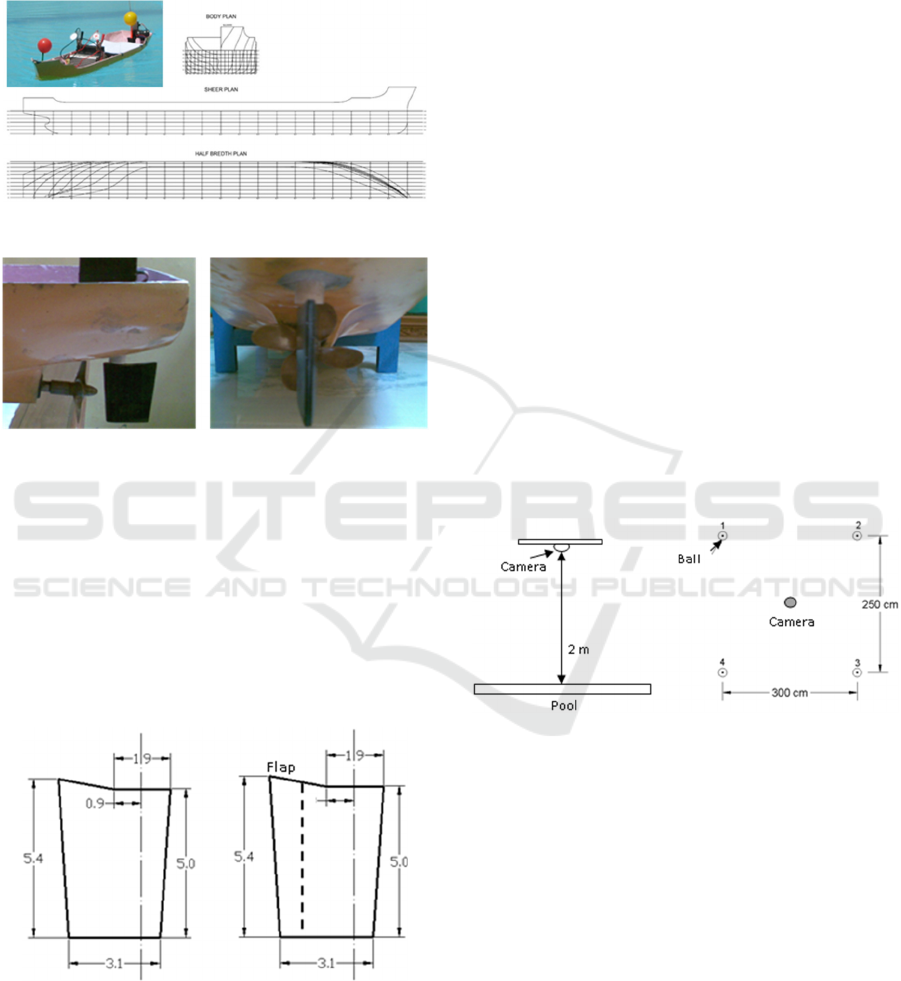
propeller shaft, and a propeller. The propeller is a
single screw with 4 blades, diameter of 5 cm, and
material of brass, which is installed in the stern
model, as shown in Figure 2.
Figure 1: Lines plan and ship model of tanker 6500 DWT.
Figure 2: Propeller and rudder on the stern of model.
In order to make the ship model manoeuvre, the
model’s hull must be equipped with the rudder
system. The servo motor with the power required 5
volts is needed to rotate the rudder, and it is remoted
in order to control the directions of the ship model.
The remote-control system consists of 2 ways such
as the command is sent according to the desire of
operator by the moving stick, and the command is
received in the form of signals which is sent by the
remote control.
Figure 3: Rudder dimensions of conventional (left) and
single flap (right).
The turning test is conducted to evaluate the
performance of the two rudder types, namely the
conventional rudder of type A, and the single flap
rudder of type B. The both section of rudders are
asymmetrical foil of NACA 0018 series, and the
wetted area of rudders are 17.6 cm
2
, as shown in
Figure 3.
2.1 Testing Procedure
The procedures of the turning test are described as
follow: First, to set up the position of the camera to
record all trajectories of the ship model where it is
installed on over the pool with the height of 4.8 m
above the water surface, see Figure 4. The camera is
connected to the computer to save or record the ship
model manoeuvring.
Second, to obtain the point signs as the reference
to figure the turning path. The 4 plastic balls that are
given light to be seen clearly when the lights are
turned off. The plastic ball is arranged into a square
shape with the distance between ball are about 250
cm and 300 cm, see Figure 4. Later the pseudo
square formed by these four plastic balls is used as a
reference to calibrate the movement of the ship's
model.
Third, to turn of all the lights around the pool, so
that the colour recorded by the camera is the colour
of the model of the ship and the lights of the ball.
The ship model is executed and recorded.
Figure 4: Position of the camera and the light ball in the
pool.
2.2 Image Processing
The video of the ship manoeuvring tests is analysed
with the following steps: first, the video recorded is
imported into the application of movie maker. The
movie is captured into several snapshots of ship
movement per each second of time. Each picture
shows the position of the ship model at every second
on the turning track, see Figure 5. The second, each
picture is identified as a point location of the ship
model, and all points are then connected to become
the line of the ship turning, see Figure 6. This ship
turning line is further analyzed to look for the
performance of ship manoeuvring.
The Simple Open Free Running Test for the Evaluation of Turning Ship Ability
117
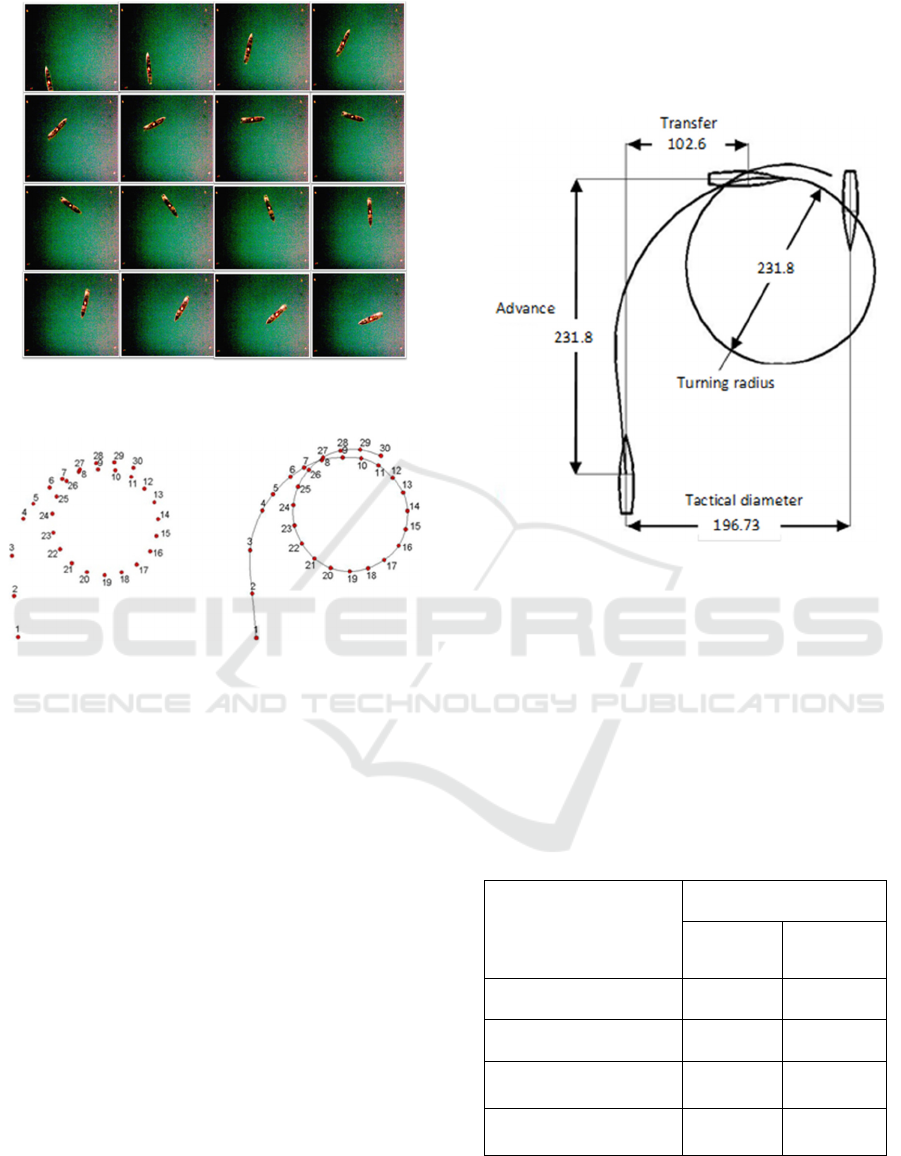
Figure 5: The position of the ship model for each time,
from 1st second to 16th second.
Figure 6: The point connected of the turning test, from 1st
second to 30th second.
3 RESULTS AND DISCUSSION
The testing of free running models is to determine
the manoeuvrability of the ship model in the turning
circle test. The rudder angle used is based on the
IMO standard which is a 35° towards the starboard
and portside of the ship. Two types of the rudder
which are the conventional and the single flap, are
evaluated their contribution in the turning manoevre.
Since the tests are carried out at night time, the lights
have to be installed on the model ship as well as on
the ball referenced in order to make it easier for the
visual analysis. The test is conducted when the wind
blow is very quiet since the wind factor contributes
to the accuracy of the test results.
The results of the free running model test are
expressed in plotting curve on the coordinate system
of xy-axis. The sway motion of ship is a transverse
motion obtained as the y-axis, and the surge motion
is a longitudinal motion toward the length of the ship
as the x-axis. For example, the results of turning test
for the model ship with the rudder-type A is plotted,
as shown in Figure 7. The parameters of ship turning
performance which are advanced, transfer, tactical
diameter, and turning diameter are measured based
on the curve turning circle.
Figure 7: Results of the turning test for the ship model
with the rudder type A (starboard).
Table 1 and 2 describe the results of the turning
test of the model with the rudder-type A (the
conventional rudder) and the rudder-type B (single
flap rudder). Based on both tables, the type B of
rudder produces smaller turning diameter while it is
compared to the type A of the rudder which is
decreases about 13.04% of Portside and 14.5% of
Starboard.
Table 1: The results of the turning test of the model with
the rudder-type A.
Item of performance
Rudder angle
35°
Portside
35°
Starboard
Advance (cm) 244.99 231.81
Transverse (cm) 101.47 102.61
Tactical
Diameter (cm)
202.94 196.73
Turning
Diameter (cm)
138.92 149.25
The comparative performance of rudder type A
and B is expressed in terms of the turning circle
curve of the full-scale ship, as shown in Figure 8.
This curve results also explain that the modification
ISOCEEN 2018 - 6th International Seminar on Ocean and Coastal Engineering, Environmental and Natural Disaster Management
118
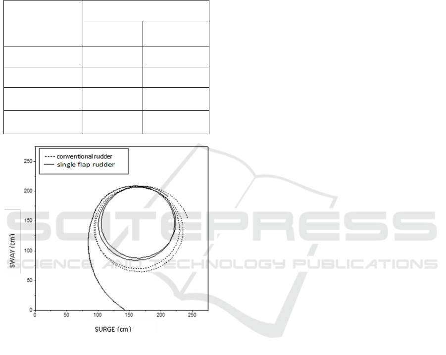
of the conventional rudder with adding the flap on
the rudder could provide an additional lift of the
rudder so that the flap makes an effect in improving
the performance of the ship manoeuvring at the sea.
Table 2: The results of the turning test of the model with
the rudder-type B.
Item of
performance
Rudder angle
35° Portside
and 10
o
flap
35° Starboard
and 10
o
flap
Advance (cm) 213.05 198.21
Transverse (cm) 88.24 87.73
Tactical
Diameter (cm)
176.48 168.22
Turning
Diameter (cm)
120.81 127.62
Figure 8: Comparison result of turning test for the model
with rudder-type A and B (starboard).
4 CONCLUSIONS
The procedures of the open free running model test
are proposed which is simply an alternative of the
ship manoeuvring test in the open water pool. The
two types of rudder such as the conventional rudder
(type A) and the single flap rudder (type B) which
are both have the same wetted surface area, are
evaluated in giving influence to the performance of
the turning manoeuvring. The test results show type
B of the rudder (single flap) produces smaller
turning diameters compared to type A of the rudder.
The flap of the rudder can increase the manoeuvre
performance of the 6500 DWT tanker ship model is
about 13.04% and 14.5% for Portside and Starboard
turning, respectively.
ACKNOWLEDGEMENTS
The author wishes to tank Rizky Hariseputera as the
student for helping in the experimental setup.
REFERENCES
A. Sulisetyono, 2014. The evaluation of a rigid sail of ship
using wind tunnel test, Applied Mechanics and
Materials, 493, pp 287-293.
A. Sulisetyono, 2014. Development of a Fish Tail Rudder
to Improve a Ship’s Maneuverability in Seaway,
IPTEK, Journal of Proceeding Series, 1.
A. Sulisetyono and A. Nasirudin, 2010. Wind Sail
Analysis Using Computational Fluid Dynamics
Simulation, The 7th International Conference on
Marine Technology (MARTEC), Dhaka Bangladesh.
A. Sulisetyono and A. Nasirudin, 2014. Experimental of
Untwisted Sail of Ship in Wind Tunnel Test, The 9th
International Conference in Marine Technology
(MARTEC), Surabaya Indonesia.
K. J. Watson, and E. C. Tupper, 2001. Basic Ship Theory
– Volume 2 Ship Dynamics and Design, Butterworth-
Heinemann, Oxford.
Lewis, and Edwards, 1989. Motions in Waves and
Controllability, Principles of Naval Architecture
Second Revision - Volume III, (The Society of Naval
Architecture and Marine Engineers (SNAME), Jersey
City.
Testing and Extrapolation Methods Manoeuvrability Free
Running Model Tests, 2008. ITTC, Manoeuvring
Committee of 25th ITTC.
The Simple Open Free Running Test for the Evaluation of Turning Ship Ability
119
