
Design Fuzzy Logic Controller PSS (Power System Stabilizer)
to Stability Improvement of Wind Turbine Penetrated
on South Sulawesi Transmission System
Agus Siswanto
1
, Arif Sumardiono
1
, and Endang Prihastuty
2
1
Electrical Engineering Study Program University of 17 Agustus 1945 Cirebon Addresses,
Perjuangan no 17 Cirebon, West Java, Indonesia
2
Machine Engineering Study Program University of 17 Agustus 1945 Cirebon Addresses,
Perjuangan no 17 Cirebon, West Java, Indonesia
Keywords: Stability, wind turbine, FLC, PSS, South Sulawesi system
Abstract: The aim of this research is to improve stability of South Sulawesi system interconnection caused by
penetration of new wind turbine in Sidrap area on bus 2 and in Jeniponto area on bus 34. The method used
in this research is through System Power Toolbox (PSAT) analysis software in under MATLAB. In this
research, there are two problems that are evaluated, namely the stability of the system before and after the
penetration of wind turbine to the system of South Sulawesi system. Conventional PSS signals are added to
control the Stability System at naturally occurring operating points, this limits PSS performance and
robustness. To solve this deficiency, the proposed design uses FLC. From the simulation result shows that
the penetration of wind turbine on bus 2 Sidrap, bus 37 Jeniponto gives oscillation effect to the system. The
oscillation was muffled by the installation of FLC Power System Stabilizer (PSS) in the bus area of 33
sinjai, that the South Sulawesi system was stable according to normal conditions.
1 INTRODUCTION
Historically South Sulawesi's transmission system is
more vulnerable to operating limiting customers and
uncertainty problems due to the lack of reactive data
requirements, the deregulation of the electricity
industry and the use of various renewable energy
sources and different operations. At present the
electric power system has evolved continually the
growth of the load is always followed by
transmission to connect power plants sourced from
renewable energy such as wind turbines and
PV(Setiadi et al., 2017). The growth of load and
pattern is based on system stability. Due to the
tapering of the membrane and the burden of
stability, stability appears according to the operating
pattern so that the use of new technology and control
is needed, to increase operation in conditions of
oscillation. Improper operating patterns can result in
frequency stability, voltage stability and interred
oscillation. However, at this time the power
stabilizer system has been used to generate and
control the voltage and frequency tuning using the
metaphorical method of the fuzzy logic controller.
There have been many successful studies on system
stability presented in the literature (Gunadin et al.,
2017), (Bian, et al., 2011), On (Rahman et al., 2018)
has discussed the stability improvement using DG
spread to correct the voltage drop that occurs due to
changes in load. Research has been done on the
penetration of wind turbines (“Stability
improvement of wind turbine penetrated using
power system stabilizer (PSS) on South Sulawesi
transmission system.,” 2018), However, the
conventional PSS strategy still needs to be
developed using artificial intelligence, namely fuzzy
logic controller, so that in this study it is proposed
that the improvement of wind turbine penetration
using fuzzy logic controller for mental gain value in
PSS is more appropriate so that the system stability
becomes more robust. The proposed method is
implemented on the South Sulawesi 44 system bus
using PSAT software. The Sulawesi system displays
using the PSAT bus voltage profile before being
234
Siswanto, A., Sumardiono, A. and Prihastuty, E.
Design Fuzzy Logic Controller PSS (Power System Stabilizer) to Stability Improvement of Wind Turbine Penetrated on South Sulawesi Transmission System.
DOI: 10.5220/0009009002340239
In Proceedings of the 7th Engineering International Conference on Education, Concept and Application on Green Technology (EIC 2018), pages 234-239
ISBN: 978-989-758-411-4
Copyright
c
2020 by SCITEPRESS – Science and Technology Publications, Lda. All rights reserved

penetrated when the wind turbine is before and after
it is installed. Voltage controllers in Sulawesi
systems with functions for fluctuations with
oscillation due to variations in wind turbine output.
2 FUNDAMENTAL THEORY
2.1 Generator, exciter, and governor
Modelin
In this study the excitation model representation
used to regulate the variables in the generator output
system includes voltage, current and power factor in
Figure. 1 and Figure 2.
K
A
1+T
A
s
V
t
+
-
V
Rmax
V
Rmin
E
fd
Figure 1: Exciter diagram block.
d
1
Tgs+1
T
m
Kg
GSC
-
+
Figure 2: Governor Modeling
The representation of the wind turbine model is
shown in Figure 3 from ref (Bevrani, 2014). On fig
4, shows from MPPT Output without measuring
wind speed, where it is noted that the maximum
power captured can be expressed as a rotation speed
cube (MPPT = ω r3) (Rosyadi and et al., 2012)
Characteristic model of wind turbine and MPPT of
difference wind speed is shown in Figure 4.
Drive
Grid
Pe
V
qr
V
dr
RSC
GSC
Pw
Figure 3: Wind Turbine.
Figure 4: Characteristics of wind turbine and MPPT
Curve.
2.2 Voltage Stability Margin (VSM)
In the VSM balance system is divided into VSM (P)
and VSM (Q). VSM (P) states that the index is
stable at active power loads and VSM (Q) for the
freedom index in the reactive load (Q). For that
system condition P critical conditions and Q are
active and reactive power at critical stress points,
respectively. The critical voltage in the system is the
value of the voltage at the point of collapse or drop
which is caused far from the voltage or performance
of the conductor. The system will discuss the
collapse voltage from zero, where the VSM critical
voltage value is zero. Equation (1) to determine
VSM:
(1)
2.3 Simplified Voltage Stability Index
(SVSI)
In the system stability study, there are several
indicators that can be used to prescribe the state of
the system that is not sturdy, which includes Voltage
collapse prediction index, L-index and voltage
stability index. Some indicators of voltage bus
stability in reference are: voltage collapse prediction
index (VCPIbus) (Balamourougan et al., 2004), L-
index (Dike and Mahajan, 2008) (Du and Deng,
2012) (Ram and Haneesh, 2016), voltage stability
index (VSIbus) in transmission system
(Kamaruzzaman and Mohamed, 2014).
critical
criticalinitial
V
VV
VSM
Design Fuzzy Logic Controller PSS (Power System Stabilizer) to Stability Improvement of Wind Turbine Penetrated on South Sulawesi
Transmission System
235

P
i
Q
i
S
i
P
j
Q
j
S
j
Vi
Ð0
Vj
Ðd
R=jX
I
Bus i
Bus j
Figure 5: Representation of two bus power system.
In Figure 5, shown the representation of two bus
systems for this study, SVSI is a derivative of the
VSI index function that is used to determine the
weak bus in the power system due to transmission
distance, definition of SVSI can be expressed as:
SVSI
i
= (2)
Voltage deviation (
i
V
) is difference between
the nearest generator with load buses. The correction
factor β [8] is expressed as :
(3)
The SVSI threshold value for keeping the system
stable refers to inequality:
Max (SVSI)<1 (4)
In the high voltage system can use this equation,
so that the advantages of this indicator are applied to
large networks. For this reason, calculations require
that the system bus voltage parameters from the
sender and receiver side can be measured from both
sides.
2.4 Power System Stabilizer (PSS)
The basic purpose of PSS installation is to widen the
stability limit by modulation of the excitation
generator to provide attenuation to synchronous
when oscillations occur due to changes in load.
Alitically, PSS can function as a transfer obtained by
PSS from wash-out and the leadlag shown in Figure
6. The lead-lag aims to provide a suitable phase lead
to compensate for the phase of the excitation lag and
the torque generator in the system.
K
PSS
Input
output
U
max-PSS
U
min-PSS
𝑝𝑇
𝑤−𝑃𝑆𝑆
1 + 𝑝𝑇
𝑤−𝑃𝑆𝑆
1 + 𝑝𝑇
3−𝑃𝑆𝑆
1 + 𝑝𝑇
4−𝑃𝑆𝑆
1 + 𝑝𝑇
1−𝑃𝑆𝑆
1 + 𝑝𝑇
2−𝑃𝑆𝑆
Figure 6: Typical controller with two lead lag stages.
2.5 Fuzzy Logic Controller (FLC))
Fuzzy logic controller is a model for the South
Sulawesi power generation system in this study. The
input of FLC is frequency (f) and the rate of change
in frequency (d
f
/d
t
). The output is to determine the
gain value on PSS. Depending on the input value,
fuzzy logic will estimate the amount of load. FLC
consists of Fuzzification, rule base, machine
interface and deffuzification steps as shown in
Figure. 7
f
dt/df
Fuzzification
Rule base/
Interface
Mechism
Defuzzification PU
Figure 7: Fuzzy Logic Controller.
From Table 1 below, a rule in fuzzy logic
controller is marked that each entry represents
certain rules and the output of the system is achieved
by using special rules articulated in the membership
function method. In this study the names for
representation used are Small Positive (PS), Positive
Medium (PM) and Positive Large (PL), Big
Negative (NL), Medium Negative (NM), Negative
Small (NS) and Zero (ZE)
Table 1: Rule for FLC.
NL
NM
NS
ZE
PS
PM
PL
NL
NL
NL
NM
NM
NS
NS
ZE
NM
NL
NM
NM
NS
NS
ZE
PS
NS
NM
NM
NS
NS
ZE
PS
PS
ZE
NM
NS
NS
ZE
PS
PS
PM
PS
NS
NS
ZE
PS
PM
PM
PL
PM
NS
ZE
PS
PM
PM
PL
PL
PL
ZE
PS
PM
PM
PL
PL
PL
3 PROPOSED METHODE
In testing the penetration of wind turbines with FLC-
PSS installations in the South Sulawesi system
network, using Figure 8, the wind turbine used was
70MW installed on bus 2 in Sidrap. PSS in Padang
on bus 33, Sinjai, this is done because the bus has a
voltage drop. This system consists of a swing bus,
fifteen bus generators, 44 bus substations. This
simulation uses Matlab Toolbox to analyze and
simulate an electric power system.
i
i
V
V
*
2
)(1 VlVMax
m
EIC 2018 - The 7th Engineering International Conference (EIC), Engineering International Conference on Education, Concept and
Application on Green Technology
236
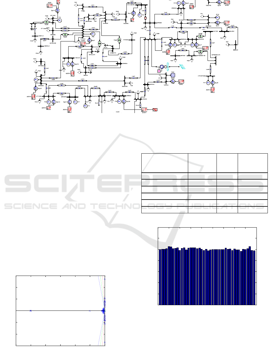
Figure 8: Sulawesi bus system.
4 SIMULATIAN AND RESULT
The simulation was tested on the 44 Sulawesi
bus system using PSAT software. This simulation
aims to obtain the influence of wind turbines on the
2 sidrap bus on the stability system using the SVSI
indicator. Figure 9 shows the Eigen value analysis of
the South Sulawesi system. Figure 10 shows the
voltage Magnitude Profile before FLC-PSS and
wind. In Table 2, address dynamic orders, number of
buses, Positive Eigen, Negative Eigen, Complex
pairs and Zero Eigen. Test system parameter values
are explained in Table 3. The result of analysis of
real power generator and reactive power generator
explained in two curve. Figure 11 shows the result
without FLC-PSS and Wind Turbine and Figure 12
shows the result with FLC-PSS and Wind Turbin.
Figure 9: Eigen value Analysis.
Table 2: Eigen Value Analysis of System With SVC.
Without
FLC-PSS
and Wind
With
FLC-
PSS
With
FLC-PSS
and wind
Dinamic Order
108
112
117
Buses
44
44
44
Positive Eigen
0
0
0
Negative Eigen
107
110
115
Complex pairs
28
26
26
Zero Eigen
1
2
2
Figure 10: Voltage Magnitude Profile before FLC-PSS
and wind.
-60 -50 -40 -30 -20 -10 0
-30
-20
-10
0
10
20
30
Real
Imag
0 5 10 15 20 25 30 35 40 45
0
0.2
0.4
0.6
0.8
1
1.2
1.4
V [p.u.]
Voltage Magnitude Profile
Bus #
Design Fuzzy Logic Controller PSS (Power System Stabilizer) to Stability Improvement of Wind Turbine Penetrated on South Sulawesi
Transmission System
237

Table 3: Test system parameter values.
bus
Real power
generation
[pu]
Without
FLC-PSS
and Wind
Reactive power
generation [pu]
Without FLC-PSS
and Wind
Real power
generation [pu]
with FLC-PSS and
Wind
Reactive power
generation [pu]
with FLC-PSS and
wind
Bus 1
1.2741
0.15092
2.3267
0.7078
Bus 2
-0.265
-0.103
-0.265
-0.103
Bus 3
-0.141
-0.034
-0.141
-0.034
Bus 4
-0.187
-0.047
-0.187
-0.047
Bus 5
0.099
-0.483739
0.099
-0.35991
Bus 6
-0.171
-0.041
-0.171
-0.041
Bus 7
0.013
0.86583
0.013
0.89607
Bus 8
-0.233
-0.037
-0.233
-0.037
Bus 9
-0.096
-0.048
-0.096
-0.048
Bus 10
0.311
-0.09708
0.311
0.12632
Bus 11
0.604
-0.18632
0.604
-0.10614
Bus 12
-0.101
-0.024
-0.101
-0.024
Bus 13
-0.221
-0.08
-0.221
-0.08
Bus 14
0
0.13352
0
0.13354
Bus 15
-0.189
-0.0206
-0.189
-0.0206
Bus 16
-0.331
-0.0154
-0.331
-0.0154
Bus 17
-0.18
-0.058
-0.18
-0.058
Bus 18
-0.432
3.2572
-0.432
3.261
Bus 19
-0.638
-0.177
-0.638
-0.177
Bus 20
0
0.21456
0
0.21454
Bus 21
-0.062
-0.28016
-0.062
-0.27972
Bus 22
-0.243
-0.026
-0.243
-0.026
Bus 23
-0.245
0.18617
-0.245
0.18615
Bus 24
0
0
0
0
Bus 25
0
0
0
0
Bus 26
0.029
-0.7146
0.029
-0.7146
Bus 27
0
0.12435
0
0.12435
Bus 28
-0.265
-0.077
-0.265
-0.077
Bus 29
0.043
-1.1396
0.043
-0.80553
Bus 30
-0.552
-0.167
-0.552
-0.167
Bus 31
0.584
0.45407
0.584
0.49081
Bus 32
-0.186
-0.005
-1.186
-1.005
Bus 33
1.961
-0.37138
1.961
-0.37981
Bus 34
0.451
-0.03284
0.451
-0.0296
Bus 35
-0.271
0.00095
-0.271
0.00094
Bus 36
0.031
0.0642
0.031
0.10058
Bus 37
-0.321
-0.01589
-0.321
-0.01661
Bus 38
-0.1108
0.25944
-0.1108
0.36008
Bus 39
-0.488
-0.02359
-0.488
-0.02359
Bus 40
0
0
0
0
Bus 41
1.95
0.25782
1.95
0.25782
Bus 42
0
0
0
0
Bus 43
-0.049
-0.005
-0.049
-0.005
Bus 44
-0.995
-0.018
-0.995
-0.018
EIC 2018 - The 7th Engineering International Conference (EIC), Engineering International Conference on Education, Concept and
Application on Green Technology
238

Figure 11: Without FLC-PSS and Wind Turbine.
Figure 12: With FLC-PSS and Wind Turbine.
5 CONCLUSIONS
In this paper, the problem of stability due to wind
turbine penetration in the 44 South Sulawesi system
is measured using SVSI. This study shows that wind
turbine integration penetration affects the stability
value of the interconnect system voltage with the
omega state indicator ω decreasing. Changes in load
and penetration rate of wind turbine determine the
critical value of the load bus which can harm the
system. The swing bus value at the beginning
without FLC-PSS is the active power value of
1.2741 and reactive power of 0.15092 then becomes
2.3267 and reactive power of 0.7078. Fuzzy tuning
in the right PSS value can improve voltage stability
in the system.
REFERENCES
Balamourougan, V., Sidhu, T.S., Sachdev, M.S., 2004.
Technique for online prediction of voltage
collapse. IEE Proc. - Gener. Transm. Distrib.
Vol 151, pp 453-460.
Bevrani, H., 2014. Robust Power System Frequency
Control, ed. Springer Cham Heidelberg New
York Dordrecht London., Second Edition.
Bian, X.Y., et al., 2011. Coordinated design of
probabilistic PSS and SVC damping controllers.
Int. J. Electr. Power Energy Syst., Vol 33, pp
445–452.
Dike, D.O., Mahajan, S.M., 2008. Utilization of L-index
in microgrid interconnected power system
network. IEEE Power Energy Soc. Gen. Meet. -
Convers. Deliv. Electr. Energy 21st Century.
Du, L., Deng, Q., 2012. Impact of Wind Power and
Photovoltaic Cell Power on Power System
Stability Based on L Index. Asia-Pac. Power
Energy Eng. Conf.
Gunadin, I.C., Muslimin, Z., Siswanto, A., 2017. Transient
stability improvement using allocation power
generation methods based on moment inertia.
Int. Conf. Electr. Eng. Inform. ICELTICs.
Kamaruzzaman, Z.A., Mohamed, A., 2014. Impact of
grid-connected photovoltaic generator using P-V
curve and improved voltage stability index.
IEEE Int. Conf. Power Energy PECon.
Rahman, Y.A., S, A., Mahmudi, I., 2018. Stability Issues
in Presence Variable Distributed Generation Into
Radial Distribution Network. Int. Conf. Ind.
Electr. Electron. ICIEE.
Ram, T.A.V., Haneesh, K.M., 2016. Voltage stability
analysis using L-index under various
transformer tap changer settings. Int. Conf.
Circuit Power Comput. Technol. ICCPCT.
Rosyadi, M., et al., 2012. Fuzzy-PI controller design for
PM wind generator to improve Fault Ride
Through of wind farm. Int. Conf. Renew.
Energy Res. Appl. ICRERA.
Setiadi, H., Krismanto, A., Mithulananthan, N., 2017.
Influence of BES system on local and inter-area
oscillation of power system with high
penetration of PV plants. Int. Conf. Appl. Syst.
Innov. ICASI.
Siswanto, A., Gunadin, I. C., Said2, S. M. and Suyuti, A.
2018, Stability improvement of wind turbine
penetrated using power system stabilizer (PSS)
on South Sulawesi transmission system., AIP
Conf. Proc. 1941, 020036.
0 5 10 15 20
0.996
0.997
0.998
0.999
1
1.001
1.002
1.003
time (s)
Syn 1
Syn 2
Syn 3
Syn 4
Syn 5
0 5 10 15 20
0.996
0.998
1
1.002
1.004
1.006
1.008
1.01
1.012
1.014
time (s)
Syn 1
Syn 2
Syn 3
Syn 4
Syn 5
Design Fuzzy Logic Controller PSS (Power System Stabilizer) to Stability Improvement of Wind Turbine Penetrated on South Sulawesi
Transmission System
239
