
An Autonomous Water Cooling System of PV
Ait Saada Sonia, Kecili Idir and Nebbali Rezki
Department of Mechanical Engineering, Laboratory of Energy, Mechanics and Materials (LEMM)
Mouloud Mammeri Universiy of Tzi Ouzou, Algeria
Keywords: Cooling, efficiency, photovoltaic panel, water.
Abstract: This study deals with the cooling of a photovoltaic solar panel (PV) by a water cooling system. We propose
to use circulating water between an insulated tank and the back side of the PV panel, with a flow rate of 50
g/s over three periods of 24 hours. 3D numerical simulations are performed using a CFD code. The results
show that the circulation of water in closed circuit, allows an effective and sustained cooling during the
three periods. Moreover, uniform temperature distribution over the entire solar panel was observed.
However, at the area of the box of electric wires the temperature rise locally.
1 INTRODUCTION
Energy consumption is steadily increasing
worldwide. The use of fossil fuels led to a rapid
increase in greenhouse gas emissions which
contribute to global warming. Thus, renewable
energies become an alternative, especially solar
photovoltaic (PV). However, its exploitation remains
dependent on climatic conditions that can
significantly affect its energy conversion
performance. Indeed, the increase in the temperature
of the PV panel affects significantly its
effectiveness. To overcome this, different cooling
techniques were adopted (Sargunanathan, Elango,
and TharvesMohideen, 2016) (Hassnuzaman et al,
2016).
(Browne et al, 2016) used the phase change
materials to cool, the PV panel. Other studies
focused on the air-cooling (Amelia et al., 2016; D.
Nebbali, R. Nebbali and Ouibrahim., 2018). (Nizetic
et al, 2016) proposed to cool the PV panel by
spraying water simultaneously on both sides of the
PV panel. This technique, in addition to being self-
cleaning, provides an increase in electric power of
16.3%. (Elnozahy et al, 2015) provided cooling by
flowing water on the glass of the PV panel. This
reduces the reflectivity on the glass surface by 2-
3.6% and ensures its cleaning. This technique
provided 22°C PV panel cooling and 8-9% power
improvement. Another study (krauter, 2004) using
this same cooling technique but enhanced by a
solenoid valve that controls the flow of water
according to the temperature of the panel. This
allows 40% reduction in panel temperature and
improves its efficiency by 11.7%. (Muzaffar et al,
2015) use water flowing through the microchannels
installed on the underside of the panel. The
temperature of the PV panel drops by 15°C while its
efficiency improves by 14%.
These techniques, although they are efficient, do
not give any information on the origin of the water
which ensures the cooling of the PV panel. To
overcome this, (Jakhar et al, 2016) proposed to cool
the solar panel with water from a water-ground heat
exchanger. The results showed that with increasing
length and diameter of the heat exchanger pipe, the
temperature of the PV panel lowered from 79.31 to
47.13 ° C for a water flow of 18 g s
-1
.
The objective of this work is to propose an
autonomous cooling system using circulating water,
in a closed circuit, between a storage tank and the
PV panel. Numerical simulations are performed to
determine the hourly evolution of the temperature of
the panel and the water of the tank.
2 POSITION OF THE POBLEM
A water tank with a capacity of 50L is considered to
provide a closed circuit cooling of a monocrystalline
PV panel (Figure 1, Table 1). Water flows through
the underside of the PV panelbefore being
reintroduced back into the tank.The panel was
cooled during three periods of 24 hours.
Sonia, A., Idir, K. and Rezki, N.
An Autonomous Water Cooling System of PV.
DOI: 10.5220/0009773503650368
In Proceedings of the 1st International Conference of Computer Science and Renewable Energies (ICCSRE 2018), pages 365-368
ISBN: 978-989-758-431-2
Copyright
c
2020 by SCITEPRESS – Science and Technology Publications, Lda. All r ights reserved
365
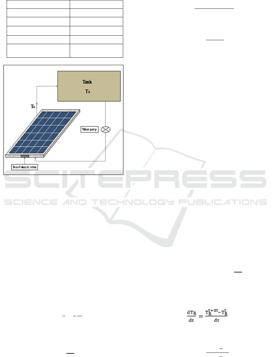
Table 1: parameters of the solar panel.
Nominal power 200 W
Voltage Vmpp 36.5 V
Current Impp 5.48 A
Number of cells 72 Cells
Dimensions of cell 125125 mm
Dimensions of the
module
158080845 mm
Figure 1: Sketch of water-cooling system of the PV.
3 METHOD
3.1 Associated Equations
The thermal balances performed on the PV panel are
expressed for the solid media of glass and silicon
(Table II), by:
3.1.1 Thermal Balance on the PV Panel
The thermal balances performed on the PV panel are
expressed for the solid media of glass and silicon
(Table II), by:
∆T
(1)
With:
a
(2)
Q
‐
‐
(3)
Q
(4)
Where:
a: is the thermal diffusivity (m2/s)
Qg : internal heat source of glass (W/m
3
)
Qsi:internal heat source of silicon (W/m
3
)
:absorptioncoefficient.
:emissivity.
:Stefan-Boltzmann constant.
Velocity and temperature field distribution of the
water flowing underside the PV panel were
determined by solving the coupled equations of
continuity, momentum and energy. To do this a
CFD-Fluent calculation code was used.
Furthermore, the upper face of the PV panel
exchange by natural convection of heat with the
ambient air. The convective exchange coefficient
was evaluated by the following correlations
(Holman, 1997)
N
0.54R
.
for 10
Ra10
(5)
N
0.15R
.
for 10
10
(6)
3.1.2 Thermal Balance of the Tank
The thermal equilibrium of the water storage tank,
assumed insulated, is expressed by:
ṁC
T
ṁC
T
MC
(7)
Considering that:
(8)
It leads to:
T
ṁ
ṁ
(9)
ICCSRE 2018 - International Conference of Computer Science and Renewable Energies
366
Where:
T
o
:the water output temperature from the PV
panel.
T
R
:the water temperature of the tank.
TABLE. II. Properties of the solar photovoltaic
panel(Armstrong and Hurley, 2010).
Layers
e
(mm)
λ
(W.m
2
k)
ρ
(kg.m
2
)
C
P
(Jkg°C)
ε
Glass 3.2 1.8 3000 500
0.7
PV cell 0.3 148 2330 677
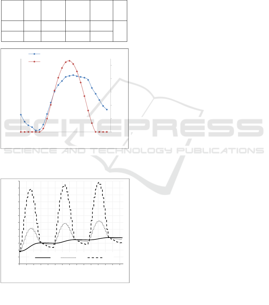
Figure 2: Hourly air temperature and solar radiation on
30
rd
June.
Figure 3: Hourly evolution of the water temperatures of
the tank (T
r
), the PV panel output (T
o
) and the silicon layer
(T
pv
) during three periods of 24 hours.
3.2 Boundary and Initial Conditions
Initial condition corresponds to the time of sunrise
(6.00 am), we consider that the reservoir water is
300K. The water circulates with a mass flow rate of
50g/s under a climate whose air temperature and
solar radiation correspond to those prevailing in
Ghardaïa (southern of Algeria) for the day of
30
rd
June 30 (National Office of Meteorology of
Algeria - ONM) (Figure 2).
4 RESULTS
4.1 Temperature of the PV Panel and
the Tank Water
Figure 3, illustrates the evolution of the water
temperatures of the tank, the output of the PV panel
and the silicon layer during three periods of 24
hours. It should be noted that at midday, during the
three periods, the mean temperature of the silicon
layer reaches the maximum value of 35.82°C,
36.49°C and 36.83°C. In fact, the water of the tank,
which feeds the PV panel, was initially at 26.85°C
before reaching 28.03°C at the end of the first
period, then 28.50°C at the second and 81°C at the
third. In addition, the temperature of the water outlet
is similar but lower than that of the silicon layer.
4.2 Temperature Field
Figure 4-6 shows the distribution of the temperature
field on the cooled solar PV panel at midday of the
three periods of 24 hours. An almost uniform
temperature distribution is observed on the whole
solar panel. Indeed, the temperature varies between
33 and 39.34°C for the first period, between 33.89
and 40.17°C for the second and between 34.27 and
40.54°C for the third one. However, at the area of
the box of electric wires, PV reaches locally the
temperatures of 44.73, 45.52 and 45.87°C. These
localized areas can significantly alter the
performances of the PV panel.
0
200
400
600
800
1000
26
28
30
32
34
36
38
40
42
44
46
0 5 10 15 20
Solar radiation (w/m2)
Temprature (°C)
Time (h)
Ambient air temprature
Solar radiation
25
26
27
28
29
30
31
32
33
34
35
36
37
5.5
10.5
15.5
20.5
25.5
30.5
35.5
40.5
45.5
50.5
55.5
60.5
65.5
70.5
75.5
Temperature (°C)
Time (h)
Tr To Tpv
An Autonomous Water Cooling System of PV
367
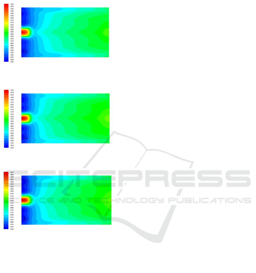
Figure 4:Temperature field on the PV panel at midday of the
first period.
Figure 5:Temperature field on the PV panel at midday of the
second period.
Figure 6:Temperature field on the PV panel at midday of the
third period.
5 CONCLUSION
In this study it was proposed an autonomous cooling
system using circulating water in a closed circuit,
between a storage tank and a PV panel. The results
showed that the PV panel temperature change
throughout the day. In fact, during the cooling
process of the PV panel, the water of the storage
tank, which was initially at 26.85°C, warms up over
the days to 28.03°C, then 28.50°C and 28.81°C,
from the first to the third periods of 24 hours.
Moreover, the temperature of the PV panel, during
these three periods,increased from 35.82°C to
36.49°C and then to 36.83°C.In order to determine
how much operating autonomy this cooling system
could provide, we need more investigations over a
longer period.
REFERENCES
S. Sargunanathan, A.Elango, S.TharvesMohideen., 2016.
Performance enhancement of solar photovoltaic cells
using effective cooling methods. In Renewable and
Sustainable Energy Reviews.
Hassnuzaman, A.B.M.A. Malek, M.M. Islam, A.K.
Pandey, N.A. Rahim., 2016. Global advancement of
cooling technologies for PV systems. In Solar
Energy.
M. C. Browne, Declan Quigley, Hanna R. Hard, Sarah
Gilligan, Nadja C. C. Ribeiro, Nicholas Almeida and
Sarah J. McCormack., 2016. Assessing the thermal
performance of phase change material in a
photovoltaic/thermal system. In Energy Procedia.
A.R. Amelia, Y.M. Irwan*, M. Irwanto*,W.Z. Leow*, N.
Gomesh*, I. Safwati**, M.A.M. Anuar., 2016
.Cooling on Photovoltaic Panel Using Forced Air
ConvectionInduced by DC Fan. InInternational
Journal of Electrical and Computer Engineering
(IJECE).
D. Nebbali, Rezki Nebbali and Ahmed Ouibrahim., 2018.
Improving photovoltaic panel performance via an
autonomous air cooling system – experimental and
numerical simulations. in International Journal of
Ambient Energy.
S. Nizetic, D. Cˇoko, A. Yadav, F. Grubišic´-Cˇabo., 2016.
Water spray cooling technique applied on a
photovoltaic panel: The performance response. In
Energy Conversion and Management.
Ahmed elnozahy, Ali K. Abdel Rahman, Ahmed Hamza
H. Alib, Mazen Abdel-Salam and S.Ookawara., 2015.
Performance of a PV module integrated with
standalone building inhot arid areas as enhanced by
surface cooling and cleaning. In Energy and Buildings.
Stefan krauter., 2004. Increased electrical yield via water
flow over the front of photovoltaic panels. In Solar
Energy Materials & Solar Cells.
Muzaffar Ali, Hafiz.M. Ali, Waqar Moazzam, and M.
Babar Saeed., 2015.Performance enhancement of PV
cells through micro-channel cooling. In AIMS Energy.
S. Jakhar, Manoj S. Soni and Nikhil Gakkhar ., 2016.
Parametric modeling and simulation of photovoltaic
panels with earth water heat exchanger cooling.In
Geotherm Energy
J. P. Holman., 1997. Heat Transfer, McGraw-Hill, 8th
edition.
S. Armstrong and W.G. Hurley., 2010. A thermal model
for photovoltaic panels under varying atmospheric
conditions. In Applied Thermal Engineering.
ICCSRE 2018 - International Conference of Computer Science and Renewable Energies
368
