
Subpixel Catadioptric Modeling of High Resolution Corneal Reflections
Chengyuan Lin and Voicu Popescu
Computer Graphics and Visualization Lab, Purdue University, West Lafayette, U.S.A.
Keywords:
Corneal Reflections, Catadioptric Modeling, Bundle Adjustment, Epipolar Geometry, 3D Reconstruction.
Abstract:
We present a calibration procedure that achieves a sub-pixel accurate model of the catadioptric imaging system
defined by two corneal spheres and a camera. First, the eyes’ limbus circles are used to estimate the positions of
the corneal spheres. Then, corresponding features in the corneal reflections are detected and used to optimize
the corneal spheres’ positions with a RANSAC framework customized to the corneal catadioptric model. The
framework relies on a bundle adjustment optimization that minimizes the corneal reflection reprojection error
of corresponding features. In our experiments, for images with a total resolution of 5, 472 × 3,648, and a
limbus resolution of 600 ×600, our calibration procedure achieves an average reprojection error smaller than
one pixel, over hundreds of correspondences. We demonstrate the calibration of the catadioptric system in
the context of sparse, feature-based, and dense, pixel-based reconstruction of several 3D scenes from corneal
reflections.
1 INTRODUCTION
Digital cameras now capture images with a resolution
that far exceeds conventional displays. Whereas a dis-
play cannot show simultaneously all the pixels of the
image, the underlying high resolution is useful for di-
gital zoom-in operations or for large format printing.
Another important benefit of high resolution is incre-
asing the quality of 3D scene reconstructions derived
from images.
Many real world scenes contain reflective objects,
and high resolution images capture a wealth of scene
information in fortuitous reflections. Reflections on
convex surfaces are particularly rich in information,
as the divergent reflected rays sample the scene com-
prehensively, with a large field of view. Furthermore,
reflections introduce additional sampling viewpoints,
which allow measuring disparity and triangulating 3D
positions from a single image.
The human eyes are convex reflectors, and resear-
chers have long speculated on the possibility of using
corneal reflections to infer 3D scene structure. One
challenge is the small baseline, i.e. a typical inter-
pupillary distance is 63 mm (Dodgson, 2004), which
translates to low depth accuracy at distances of 0.5 m
and beyond. Another challenge is the low resolution
of the corneal reflections. Both challenges are allevi-
ated by increases in the overall image resolution. A
third challenge is accurate calibration of the catadiop-
tric system defined by the two eyes and a camera. An
accurate catadioptric model is needed to limit the se-
arch for correspondences between corneal reflections
to 1D epipolar curves, and for accurate triangulation
of 3D scene points.
In this paper we present a procedure for calibra-
ting the catadioptric model defined by two corneal
spheres and a camera. The input is a high resolution
image of a person looking at a 3D scene. In our ex-
periments, the image resolution is 5, 472 × 3, 648 and
each corneal reflection has a resolution of approxima-
tely 600 × 600. First, a preliminary corneal catadiop-
tric model is inferred from the projection of the lim-
bus circles in the corneal reflections. Then, the model
is refined iteratively using a custom RANSAC appro-
ach that relies on bundle adjustment to minimize fe-
ature reprojection error. We obtain an error between
0.16 and 0.58 pixels. We use the corneal catadioptric
model to recover dense depth through stereo matching
with the support of epipolar-like constraints (Figure
1). The truth geometry used for comparison (grey
points in Figure 1c) was obtained by scanning the toys
with an active depth sensing camera.
2 PRIOR WORK
We first give an overview of prior efforts on acqui-
ring scenes using catadioptric imaging systems, and
then we review prior work in modeling the catadiop-
Lin, C. and Popescu, V.
Subpixel Catadioptric Modeling of High Resolution Corneal Reflections.
DOI: 10.5220/0007308506730683
In Proceedings of the 14th International Joint Conference on Computer Vision, Imaging and Computer Graphics Theory and Applications (VISIGRAPP 2019), pages 673-683
ISBN: 978-989-758-354-4
Copyright
c
2019 by SCITEPRESS – Science and Technology Publications, Lda. All rights reserved
673
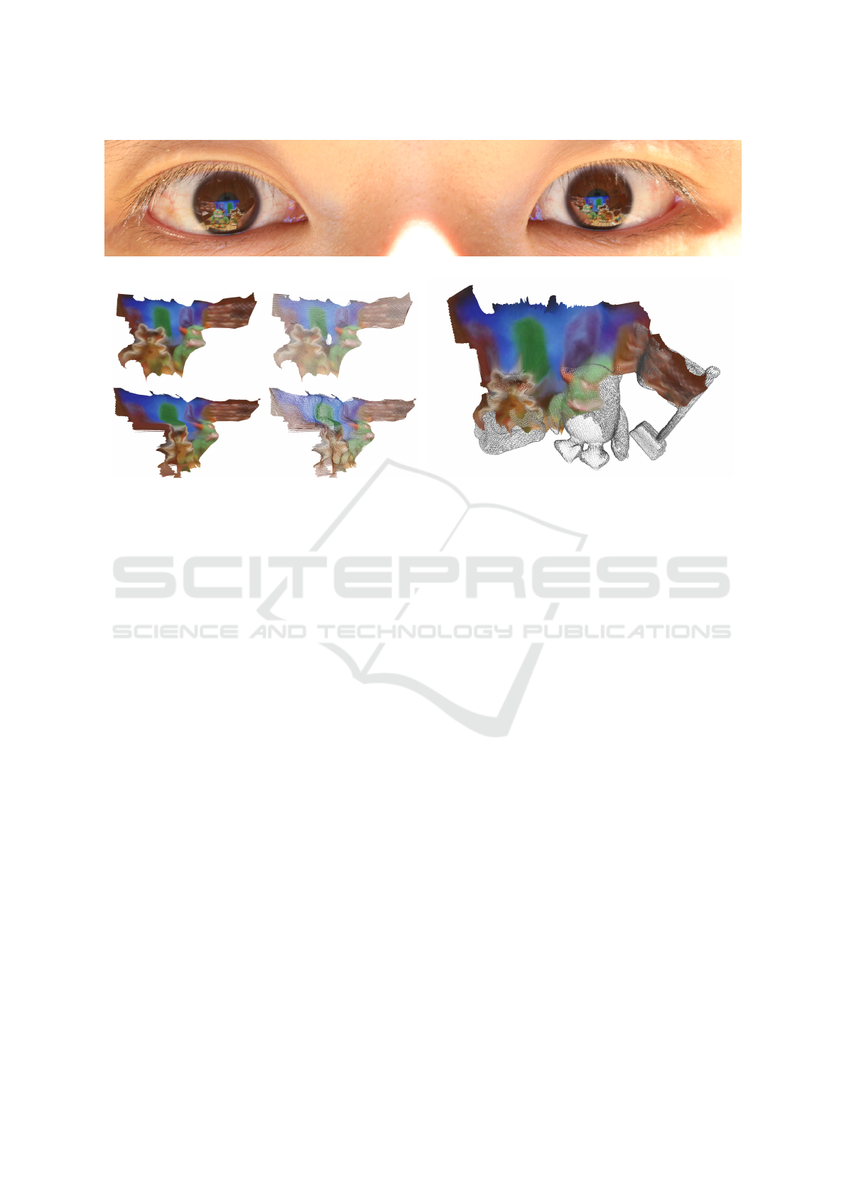
(a) Input image cropped to eye region.
(b) 3D reconstruction visualized in filled and wireframe
mode.
(c) 3D reconstruction (shaded) aligned with truth geometry
(grey).
Figure 1: 3D scene reconstruction with our catadioptric modeling approach.
tric imaging system defined by a camera and the two
human eyes.
Researchers have long noticed the benefits of de-
vising acquisition systems that combine refractive and
reflective elements. One such benefit is an increa-
sed field of view. Debevec used a chrome ball as a
light probe to capture the complex illumination of a
real world scene with a single shot, and to apply it to
synthetic objects integrated into the scene (Debevec,
2008). Nayar has developed omnidirectional cameras
using paraboloidal mirrors with a single viewpoint, so
their images can be resampled to conventional ima-
ges (Nayar, 1997). A second scene acquisition be-
nefit of catadioptric systems is the ability to integrate
multiple perspectives in the same image. The additi-
onal perspectives encode depth disparity, which ena-
bles single-shot depth from stereo (Kuthirummal and
Nayar, 2006). The additional perspectives are also
useful for devising acquisition systems that are robust
to occlusions, by guiding the scanning laser beam to-
wards hard-to-reach places (Fasano et al., 2003).
Human eyes are often captured in images, and
leveraging corneal reflections to infer information
about the scene is appealing and has been carefully
studied (Nitschke et al., 2013). The corneal reflecti-
ons are readily available, without the challenge of
augmenting the camera with reflective elements. Furt-
hermore, the corneal reflections introduce additional
viewpoints that capture parts of the scene missed from
the camera viewpoint. The additional viewpoints not
only provide a comprehensive image of the scene,
but also allow measuring disparity to extract depth.
The catadioptric system defined by a camera and two
eyes requires modeling the cornea’s reflective surface.
Prior work models this surface as a sphere cap, which
is part of the corneal sphere, and delimited by the
sclera sphere (Nishino and Nayar, 2006). We use the
same cornea surface model. Another challenge is that,
unlike for catadioptric imaging devices where the re-
flective elements have a fixed, pre-calibrated position
and orientation with respect to the camera, in the case
of corneal reflections the eyes are free to move with
respect to the camera, and their position has to be re-
covered in every image.
One use of corneal reflections is to capture a pano-
ramic image of the scene, leveraging the large field of
view sampled by the reflected rays (Nishino and Na-
yar, 2006). The information in the corneal reflection
can be used to extract gaze direction in camera-
display systems (Nitschke et al., 2011a), and also to
extract a panorama of the environment reflected in the
user’s eyes (Nitschke and Nakazawa, 2012). Corneal
reflections have also been proposed as a way of gai-
ning insight into a crime scene, demonstrating that ca-
mera resolution is now sufficient for identifying hu-
mans present in such reflections (Jenkins and Kerr,
2013).
We discuss in detail the two prior art papers most
VISAPP 2019 - 14th International Conference on Computer Vision Theory and Applications
674

relevant to our work. One describes a system that does
not recover 3D scene structure from corneal reflecti-
ons, but rather from parabolic metal mirrors (Agra-
wal et al., 2011). Metal mirrors greatly simplify ca-
tadioptric scene reconstruction by providing a preci-
sely known reflective surface shape, and by genera-
ting clear and high contrast reflections. Furthermore,
metal mirrors are perfectly stationary which avoids
the blurriness that results from the slight user head
motion as the picture is taken. Moreover, the metal
mirrors used are about three times larger than the cor-
neal sphere, and about four times larger than the lim-
bus circle, which delimits the reflection in our case.
Consequently, the prior work reflections have a re-
solution of 2M pixels, compared to the 0.1M pixels
for our work, which aids significantly with recon-
struction quality. The earlier system refines calibra-
tion without a preliminary RANSAC step to weed out
mismatched features. The reprojection error achieved
by the earlier system is about five times larger than
ours, most likely due to the simpler calibration refi-
nement step, as discussed above. Finally, the earlier
work does not report any quantitative measure of the
3D reconstruction error. Our work validates the 3D
reconstruction quality in an absolute sense by recon-
structing objects of known size, as discussed in the
following sections.
The other paper highly relevant to our work is
the only prior art paper that actually recovers any 3D
structure from corneal reflections (Nishino and Na-
yar, 2004). The paper proposes the idea of finding
correspondences between a pair of corneal reflections
and of triangulating them into depth. We extend this
work in the following ways. First, the earlier system
calibration stops at our precalibration phase. The ear-
lier system is crudely calibrated by inferring the po-
sition of the corneal spheres from the limbus circles,
whereas our system refines this initial calibration with
our custom RANSAC + bundle adjustment approach,
which reduces the reprojection error substantially. We
achieve sub-pixel accuracy, whereas the previous pa-
per doesn’t report calibration accuracy, which we es-
timate as being orders of magnitude lower based on
the accuracy achieved by our similar precalibration
stage. Second, the earlier system requires establishing
correspondences between the two corneal reflections
manually, by clicking corresponding points. Our sy-
stem detects, matches, and validates correspondences
automatically. Third, the earlier system does not per-
form dense stereo reconstruction, whereas our system
does. Finally, the only scene where 3D reconstruction
is demonstrated is that of a large cube with uniformly
colored faces. Inspired by their pioneering work, with
the help of our subpixel catadioptric modeling fra-
(a) Outer view. (b) Geometric model.
Figure 2: Eye model.
mework, we demonstrate 3D scene structure recovery
from corneal reflections.
3 CATADIOPTRIC MODEL OF
CORNEAL REFLECTIONS
Many scenes of interest to computer vision applicati-
ons contain humans, and corneal reflections present
the opportunity for catadioptric stereo scene recon-
struction. Before scene reconstruction can begin, one
has to model the catadioptric system defined by two
eyes and a camera.
3.1 Eye Model
Figure 2a shows an outer view of the human eye. The
most distinctive components are the color-textured
iris and the surrounding white sclera. The cornea is
the transparent outer layer of the eye that covers the
iris. The cornea has an internal pressure higher than
that of the atmosphere, which maintains the cornea’s
convex shape. The cornea surface is coated with a
thin film of tear fluid which makes it smooth, with
mirror-like reflective characteristics (Nitschke et al.,
2011b).
Geometrically, the eye is well approximated by
two intersecting spherical segments of different radii:
a smaller, anterior corneal segment, and a larger, pos-
terior scleral segment (Figure 2b). The intersection of
the two segments defines the limbus circle, i.e. the pe-
rimeter of the iris. In the field of anatomy, extensive
measurements of the shape and dimensions of the cor-
nea have been conducted (Mashige, 2013). The cor-
neal segment covers about one-sixth of the eye, and
has a radius of curvature r
C
of 7.8 mm. The radius of
the limbus circle r
L
is 5.5 mm. The displacement d
LC
between the center of the limbus circle and the center
of the corneal sphere can be obtained as
d
LC
=
q
r
2
C
− r
2
L
≈ 5.53mm .
(1)
Subpixel Catadioptric Modeling of High Resolution Corneal Reflections
675

Figure 3: Corneal catadioptric imaging system.
3.2 Catadioptric Model
We model the catadioptric system defined by a camera
and two eyes with the following parameters: (1) the
intrinsic parameters of the camera, (2) the limbus ci-
rcle radius r
L
, (3) the corneal sphere radius r
C
, and
(4) the 3D positions of the centers of each of the two
corneal spheres in the camera coordinate system.
We measure the camera intrinsic parameters with
a standard calibration process (Zhang, 1999). We as-
sume that both eyes have the same limbus circle ra-
dius, and we use the average value of 5.5 mm. We as-
sume both corneal spheres have the same radius, and
we use the average value of 7.8 mm. We confirm the
validity of these assumptions in Section 5.3. The 3D
positions of the corneal sphere centers are found for
each image as described in the next section.
Using the catadioptric model (Figure 3), given a
pixel s in the corneal reflection, one can compute the
corresponding reflected ray SP by reflecting the ca-
mera ray OS off the corneal sphere. The converse,
projection operation is more challenging. Given a
scene 3D point P, we compute its corneal reflection
projection s = π(C, P) by first finding its reflection
point S with a fourth order equation (Eberly, 2008).
Then s is computed by projecting S on the image
plane.
3.3 Epipolar Geometry
Epipolar geometry is used in stereo matching to re-
duce the dimensionality of the correspondence se-
arch space from two to one. In our case the rays re-
flected by the corneal sphere are not concurrent, so
the epipole is ill-defined, and traditional epipolar ge-
ometry does not apply. However, we derive epipolar-
like constraints as follows. Given a pixel s
1
in the
left corneal reflection (Figure 4), we compute its left
corneal sphere reflected ray r
r
r, we sample r
r
r with 3D
points, and we project each 3D point P onto the image
plane using the right corneal sphere, leveraging the
projection operation described above. The projected
points define an epipolar curve in the right corneal
Figure 4: Epipolar geometry of corneal catadioptric system.
Figure 5: System pipeline overview.
reflection which is known to contain the correspon-
dence s
2
of s
1
, if such a correspondence exists. Like
in traditional stereo, the search for correspondences is
confined to a 1D subset of the image pixels. We note
that the epipolar curve can be described analytically
with a quartic (Agrawal et al., 2010). However, we
have opted to sample the epipolar curve by sampling
the 3D ray for a better control of the sampling rate,
as it is challenging to sample a high-order parametric
curve with steps of equal Euclidean length.
4 SYSTEM PIPELINE
Figure 5 shows the stages of our system pipeline. Ple-
ase also refer to the supplementary video for results
of each stage.
4.1 Eye Region Extraction
The first stage crops the input image to only contain
the eyes region. We use a Haar feature-based cascade
classifier specialized for eye detection, proposed by
Viola (Viola and Jones, 2001) and improved by Lien-
hart (Lienhart and Maydt, 2002). Previous approa-
ches for extracting the eye regions proceed with a pre-
liminary step of finding the faces in the input image.
In our case, a single face dominates the input image,
and it can even happen that an image does not capture
the entire face, so face detection is not necessary, and
sometimes not even possible.
VISAPP 2019 - 14th International Conference on Computer Vision Theory and Applications
676
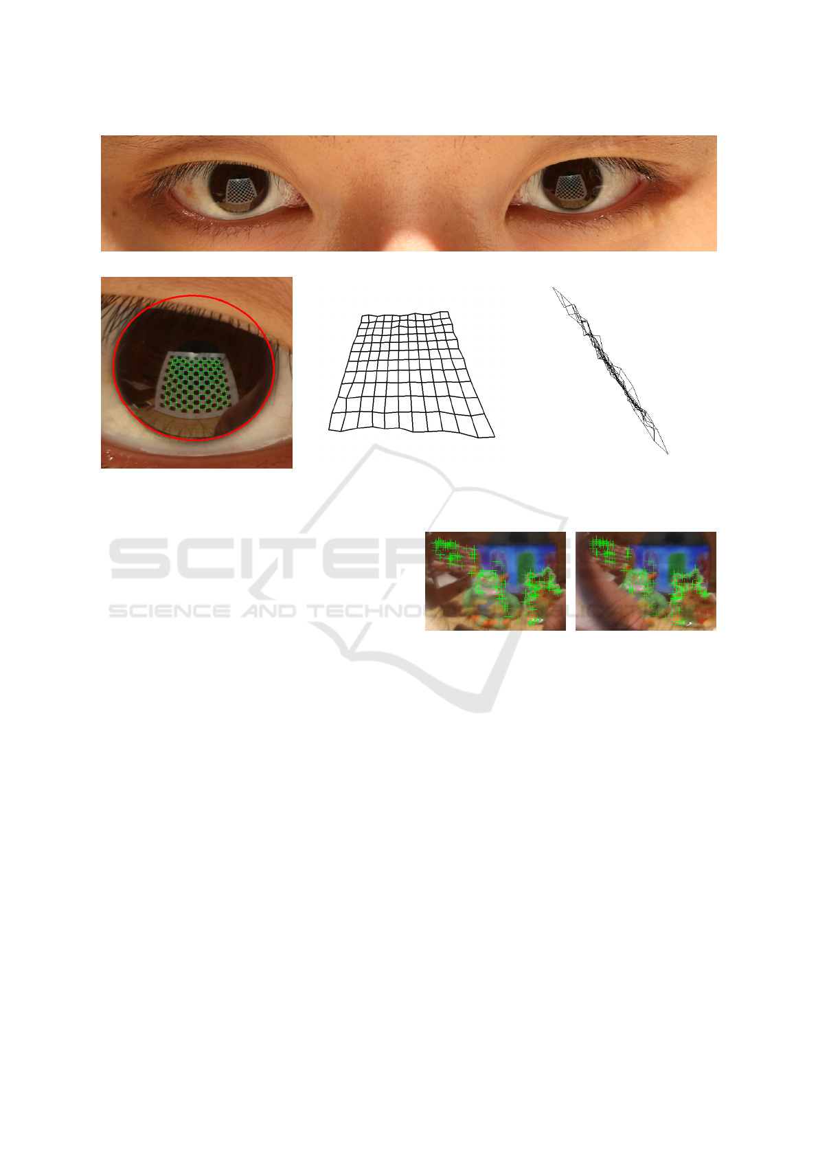
(a) Eye region of input image.
(b) Limbus and feature detection. (c) Reconstructed checkerboard. (d) Side view of checkerboard.
Figure 6: 3D reconstruction of checkerboard. The average out of plane displacement for the checker corners is 7.3 mm.
4.2 Initial Calibration
The second stage of the pipeline derives an estimate of
the position of the corneal spheres in the camera coor-
dinate system. This is achieved with a method similar
to the one described before in the context of achieving
super-resolution of corneal reflections (Nitschke and
Nakazawa, 2012). We summarize the procedure here
for completeness.
The limbus projection is detected in each eye re-
gion using a weak perspective assumption. Prior art
has also developed methods for recovering the limbus
under full-perspective projection assumption (Schnie-
ders et al., 2010). However, the weak-perspective as-
sumption is justified by the small limbus diameter re-
lative to the distance to the camera, and by the fact
that at this stage we are only deriving an initial es-
timate that is then refined in the subsequent pipeline
stages.
The ellipse corresponding to the limbus projection
is found in a downsampled eye region image using
a Canny edge detector. Edge segments are assem-
bled from edge map pixels and the ellipse is assem-
bled from edge segments with a combinatorial se-
arch (Kassner et al., 2014). The downsampling of
the eye region not only helps accelerate ellipse de-
tection, but also serves as a low-pass filter that im-
proves robustness. In particular, the downsampling
suppresses the corneal reflections, which are an im-
Figure 7: Corneal reflection feature points for Figure 1.
portant source of noise for this stage of the pipeline.
Note that the limbus circle is never entirely visible, as
it is occluded by eyelids and eyelashes. Our edge de-
tection/combinatorial search method handles well the
variable occlusion of the limbus. Figure 6b shows a
limbus detection example. Once the ellipse is deter-
mined, using the known radius of the limbus circle,
the 3D position of the center and the orientation of
the limbus circle are computed leveraging the known
camera intrinsics. Since the radius of the corneal sp-
here is known, the corneal sphere center is computed
using the 3D position of the center and the normal of
the limbus plane (Schnieders et al., 2010).
4.3 Feature Extraction
The third stage of the pipeline extracts features in the
reflections within the two limbus ellipses. We de-
tect features using the FAST algorithm (Rosten and
Drummond, 2006) (Figure 7). In anticipation of fe-
Subpixel Catadioptric Modeling of High Resolution Corneal Reflections
677

Algorithm 1: Refinement of catadiotpric model.
Input: Initial catadioptric model C
0
, features F
L
and
F
R
, # of iterations k
Output: Feature matching M, and refined
catadioptric model C
1: M
0
= InitialMatching(F
L
, F
R
)
2: for each iteration i of k do
3: hex
i
= {( f
L1
, f
R1
), . . . , ( f
L6
, f
R6
)} ⊂ M
0
4: C
i
= BundleAdjustment(C
0
, hex
i
)
5: for each (l
j
, r
j
) in M
0
do
6: e
i j
= ReprojectionError((l
j
, r
j
),C
i
)
7: if e
i j
< ε then // inlier correspondence
8: M
i
+= (l
j
, r
j
), n
i
++
9: if n
i
> n
best
then
10: n
best
= n
i
, M = M
i
, C
best
= C
i
11: C = BundleAdjustment(C
best
, M)
ature matching, the features are described with the
BRIEF (Calonder et al., 2010) algorithm. Feature
scale and orientation will not vary much between the
reflection in the left eye and the reflection in the right
eye. Therefore, the additional memory and proces-
sing costs of scale and orientation invariant descrip-
tors such as SIFT (Lowe, 1999) or SURF (Bay et al.,
2006) are not justified in our context. The BRIEF des-
criptor is binary, so the hamming distance between
two descriptors can be found quickly using XOR and
counting bit operations.
4.4 Calibration Refinement
The fourth stage of the pipeline refines the catadiop-
tric model with a RANSAC approach we have deve-
loped (Algorithm 1). The algorithm takes as input the
initial catadioptric model C
0
estimated from the lim-
bus circle projections in the second stage of the pi-
peline; the set of features F
L
and F
R
detected in the
left and right corneal reflections in the third stage of
the pipeline; and the number of RANSAC iterations k
over which to refine the catadioptric model.
An initial matching of features M
0
is computed
(line 1) with an all-pairs approach that considers each
feature f
L
in F
L
and matches it to the F
R
feature with
the smallest distance to f
L
. However, in the case of
scenes with repetitive texture, a feature could have se-
veral matches with similar quality, which can lead to
matching ambiguity. We reject such features using the
ratio test (Lowe, 1999), which only keeps a feature if
its second best match is significantly worse.
Based on this initial matching M
0
, each iteration
i of the RANSAC approach computes a possible refi-
ned catadioptric model C
i
, and retains the best refine-
ment (lines 2-10). The refined model C
i
is computed
Figure 8: Detected features (green) and reprojected features
(red). The average reprojection error is 0.54 pixels.
with a bundle adjustment approach from a set of six
correspondences hex
i
that are drawn at random from
M
0
(line 3). The bundle adjustment uses a trust-region
optimization (Conn et al., 2000) to find the two cor-
neal centers C
L
and C
R
(2×3 = 6 parameters), and the
3D positions P
j
of the six scene features (6 × 3 = 18
parameters). The optimization minimizes the sum of
correspondence reprojection errors. For correspon-
dence ( f
L j
, f
R j
) the reprojection error is:
π (C
L
, P
j
) − f
L
j
2
+
π (C
R
, P
j
) − f
R
j
2
, (2)
where π is the projection function of the corneal
catadioptric system (Section 3.2). An initial guess
of a feature’s 3D position P
j
is computed by trian-
gulation, as the midpoint of the common perpendicu-
lar segment of the two reflected rays at f
L j
and f
R j
).
The six correspondences are sufficient to determine
the 6 + 18 = 24 parameters, since each of the six cor-
respondences contributes two 2D corneal projection
equations, for a total of four scalar equations:
π(C
L
, P
j
)
x
= f
L
jx
, π(C
L
, P
j
)
y
= f
L
jy
,
π(C
R
, P
j
)
x
= f
R
jx
, π(C
R
, P
j
)
y
= f
R
jy
.
(3)
Then, using the model C
i
, the correspondences in
M
0
are partitioned in inlier and outlier corresponden-
ces (lines 5-8). A correspondence is considered an in-
lier if its reprojection error e
i j
(Equation 2) is smaller
than a threshold ε. Inlier correspondences are coun-
ted by n
i
, and are collected in set M
i
. The model C
best
with the most inlier correspondences is found over all
k RANSAC iterations (lines 9-10). In a last step, C
best
is refined over all inlier correspondences M with the
bundle adjustment procedure described above for line
4), to generate the final catadioptric model C. The
catadioptric model refinement reduces the average re-
projection error to subpixel levels (Figure 8).
In conventional structure from motion, bundle ad-
justment is used over multiple frames, which results
VISAPP 2019 - 14th International Conference on Computer Vision Theory and Applications
678

Figure 9: Correspondence search on epipolar curve (top),
and rotation of corresponding patches (bottom).
in a large but sparse feature correspondence matrix.
This sparsity is exploited by specific optimization
methods (e.g. Sparse Bundle Adjustment based on
Levenberg-Marquardt (Lourakis and Argyros, 2009)).
In our case, we only rely on the two images provided
by the two corneal reflections, so our correspondence
matrix is always full and small, hence our choice of
the trust-region optimization.
4.5 Dense Stereo
The catadioptric model refinement stage produces
a sparse reconstruction of scene geometry by com-
puting the 3D positions of corresponding features.
Scene reconstruction fidelity is increased in a final
stage that attempts to compute a correspondence, and
thereby a 3D point, for each corneal reflection pixel.
For every pixel in the left corneal reflection we search
for a correspondence p
R
in the right corneal reflection
along p
0
L
s epipolar curve (Figure 9, top). The epi-
polar curve (blue) is truncated to a short arc (red) ba-
sed on a depth range estimate inferred from the sparse
reconstruction. The smaller search space accelerates
correspondence finding, and increases robustness by
removing from consideration parts of the image with
similar texture.
Given a candidate corresponding point p
R
on the
epipolar curve, the matching error E(p
L
, p
R
) is the
sum of squared color differences between square pat-
ches R
p
L
and R
p
R
centered at p
L
and p
R
in the left and
right reflections:
E(p
L
, p
R
) =
∑
p
i
⊂R
p
L
k
R
p
L
(p
i
) − R
p
R
(F(p
i
))
k
2
. (4)
Whereas in standard stereo configuration the map-
ping F from R
p
L
to R
p
R
can be approximated with the
identity, in our case there is significant rotation be-
tween R
p
L
and R
p
R
. We use a mapping that rotates
each patch to become aligned with the epipolar curve
tangent (Figure 9, bottom).
Figure 10: Experiment setup.
5 RESULTS AND DISCUSSION
Figure 10 shows our experimental setup. All the pic-
tures were taken with a Canon E70D camera, which
has a resolution of 5,472 x 3,648, and with a 135 mm
lens. Aperture, ISO and shutter time were chosen to
best capture the corneal reflections. Focus bracketing
was used to obtain sharp corneal reflections, which
is also aided by the fact that the reflection in a small
convex surface is ”shallow”, forming close to the re-
flective surface, and focusing close to the surface will
capture the entire reflection in focus, even for a small
depth of field. We have tested our pipeline on se-
veral scenes: Checkerboard (Figure 6), Toys (Figure
1), Presents (Figure 11), and Workbench (Figure 12).
5.1 Quality
The automatically detected ellipse has an average
Hausdorff distance of 1.51 pixels to a truth ellipse fit-
ted through manually chosen points (Rockafellar and
Wets, 2009).
We extract features with OpenCV’s FAST feature
detector (Rosten and Drummond, 2006). The initial
feature matching (line 1 in Algorithm 1) has a low
outlier rate, e.g. 8 out of 106 for the Toys scene. Con-
sequently, a small number of RANSAC iterations (i.e.
k = 10) are sufficient to converge to an accurate cata-
dioptric model since the randomly selected sets of six
correspondences are unlikely to contain outliers. The
refinement stage reduces the average reprojection er-
ror (Equation 2) substantially, as shown in Table 1.
For the Workbench scene the limbus is heavily occlu-
ded in the input image, so limbus detection is approx-
imate, which leads to a coarse initial calibration. Ho-
wever, even for this case, model refinement conver-
ges, reducing the reprojection error below one pixel.
For the Checkerboard scene, the average out of
plane displacement for the 144 3D points recovered at
the 12×12 checker corners is 7.3 mm. For the dense-
stereo reconstructed points, the average out of plane
Subpixel Catadioptric Modeling of High Resolution Corneal Reflections
679
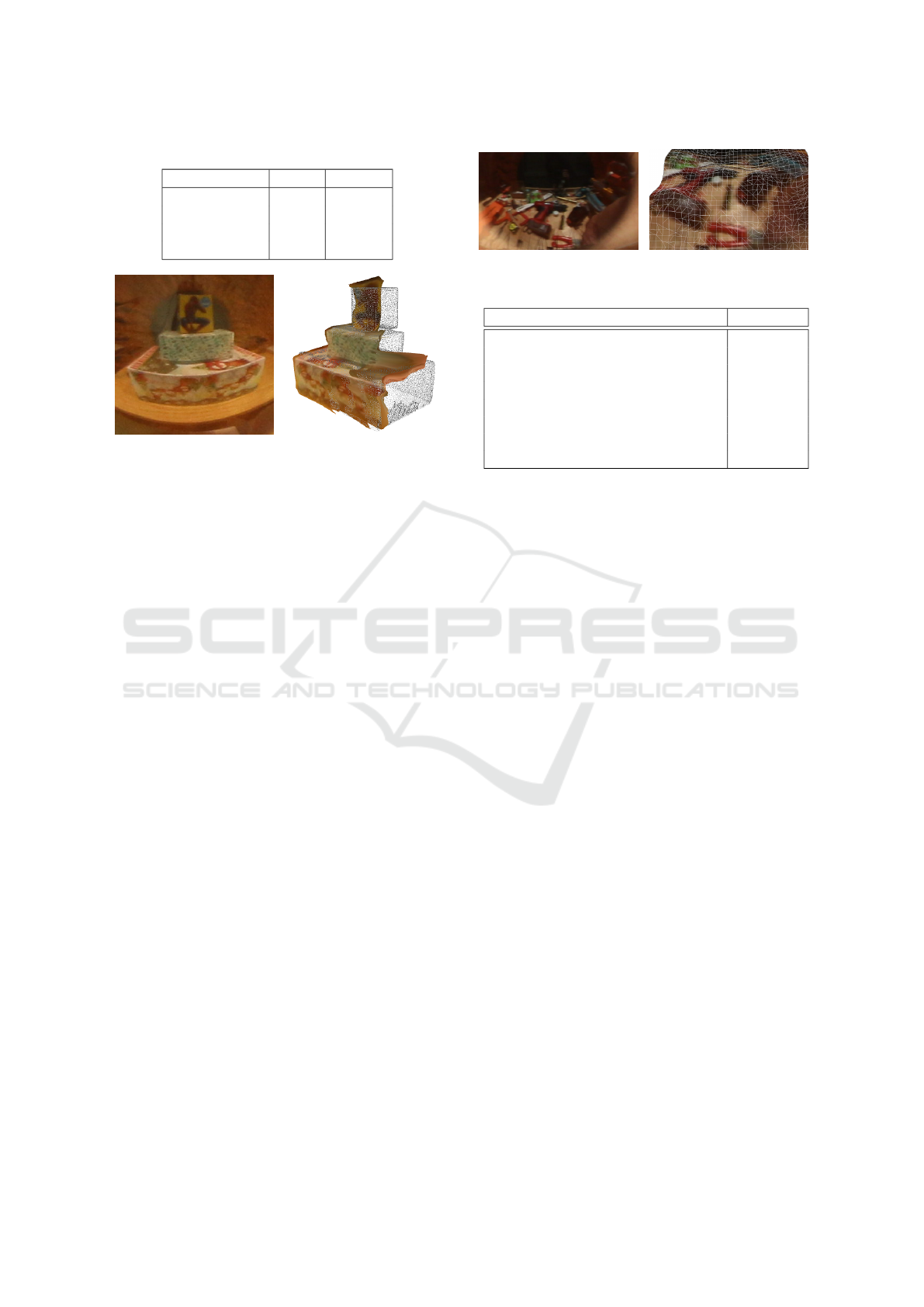
Table 1: Reprojection errors [pixel].
Initial Refined
Checkerboard 2.44 0.16
Toys 7.93 0.54
Presents 13.88 0.57
Workbench 62.26 0.58
Figure 11: Presents scene: reflection, and reconstruction
aligned with truth geometry (grey points), for comparison.
displacement is also 7.3 mm. The length of the recon-
structed diagonal of the checkerboard is 0.61 m, whe-
reas the true diagonal is 0.59 m, which corresponds
to a 2.7% error. For a qualitative assessment of our
depth maps, we scanned the Toys and the Presents
scenes with a depth camera (i.e. a Structure sensor).
The truth geometry aligns with the geometry recon-
structed from corneal reflections (Figures 1c and 11).
For the Presents scene we fitted planes to the box fa-
ces, with an average error of 15.3 mm. The normals
of parallel faces had an average angle error of 6.2
◦
.
5.2 Speed
We measured performance on an Intel(R) Core(TM)
i5-7600K 3.8GHz workstation. The running times of
each stage of our pipeline are given in Table 2. For
eye region extraction, we use the Haar cascade classi-
fier provided in OpenCV. A minimum eye region size
is set to avoid false detections. For the limbus de-
tection in the initial calibration, we start the search at
the center of the eye region. The bulk of the limbus
detection time goes to downsampling the image. The
dense stereo stage is by far the slowest, but also the
best candidate for parallelization.
5.3 Error Analysis
Like any depth from stereo system, our depth accu-
racy depends on the baseline, on the image resolu-
tion, and on the correspondence detection error. There
isn’t much flexibility for the baseline, which is fixed
to the interpupillary distance. In terms of resolution,
we use one of the off-the-shelf highest resolution ca-
meras. Due to the high curvature of the corneal sp-
Figure 12: Workbench scene: reflection and reconstruction.
Table 2: Typical running times for our pipeline.
Pipeline stage Time [ms]
Eye region extraction 53
Initial calibration 82
Feature extraction 50
Calibration refinement (Algorithm 1)
Initial feature matching (line 1) 2
RANSAC iterations (lines 2-10) 20
Final bundle adjustment (line 11) 1,053
Dense Stereo 287,327
here, correspondence detection errors result in larger
depth errors than in the case of conventional stereo,
as reflected rays are more divergent. The detection
error is commensurate to the feature reprojection er-
ror, which in our experiments is consistently below
one pixel. For our system, a one pixel detection er-
ror translates to an average depth error of 20 mm at
0.5m. This error is larger closer to the limbus circle,
where reflected rays are more divergent.
We use a catadioptric model that assumes known
and equal limbus circle radii. The limbus circle radius
is only used in the initial calibration stage, which pro-
vides an initial guess for the model refinement stage.
In all our experiments this initial guess was good
enough for the model refinement stage to converge,
which indicates that one can safely use the known and
equal limbus circle radii assumption. Our catadioptric
model also assumes that the corneal surfaces are sp-
herical, and that the corneal sphere radii are known
and equal. We have investigated the reconstruction
error sensitivity to deviations from these two assump-
tions analytically. The reconstruction error is compu-
ted for a 3D point P at a typical distance from the eyes
of 0.5 m. The projections p
L
and p
R
of P in the cor-
neal reflections are computed with our ideal catadiop-
tric model C . Then, for a given imperfect catadioptric
model C
0
, we compute a deviated position P
0
of P as
follows. First, the camera rays at p
L
and p
R
are re-
flected according to C
0
, and then the reflected rays are
triangulated to obtain P
0
. The reconstruction error is
defined as the Euclidean distance between P and P
0
.
Figure 13 shows the reconstruction error depen-
dence on cornea eccentricity and on left/right eye
asymmetry. The same 0 to 0.2 range is used for both
independent variables. Cornea eccentricity is mo-
deled by assuming the true cornea is in fact an ellip-
VISAPP 2019 - 14th International Conference on Computer Vision Theory and Applications
680
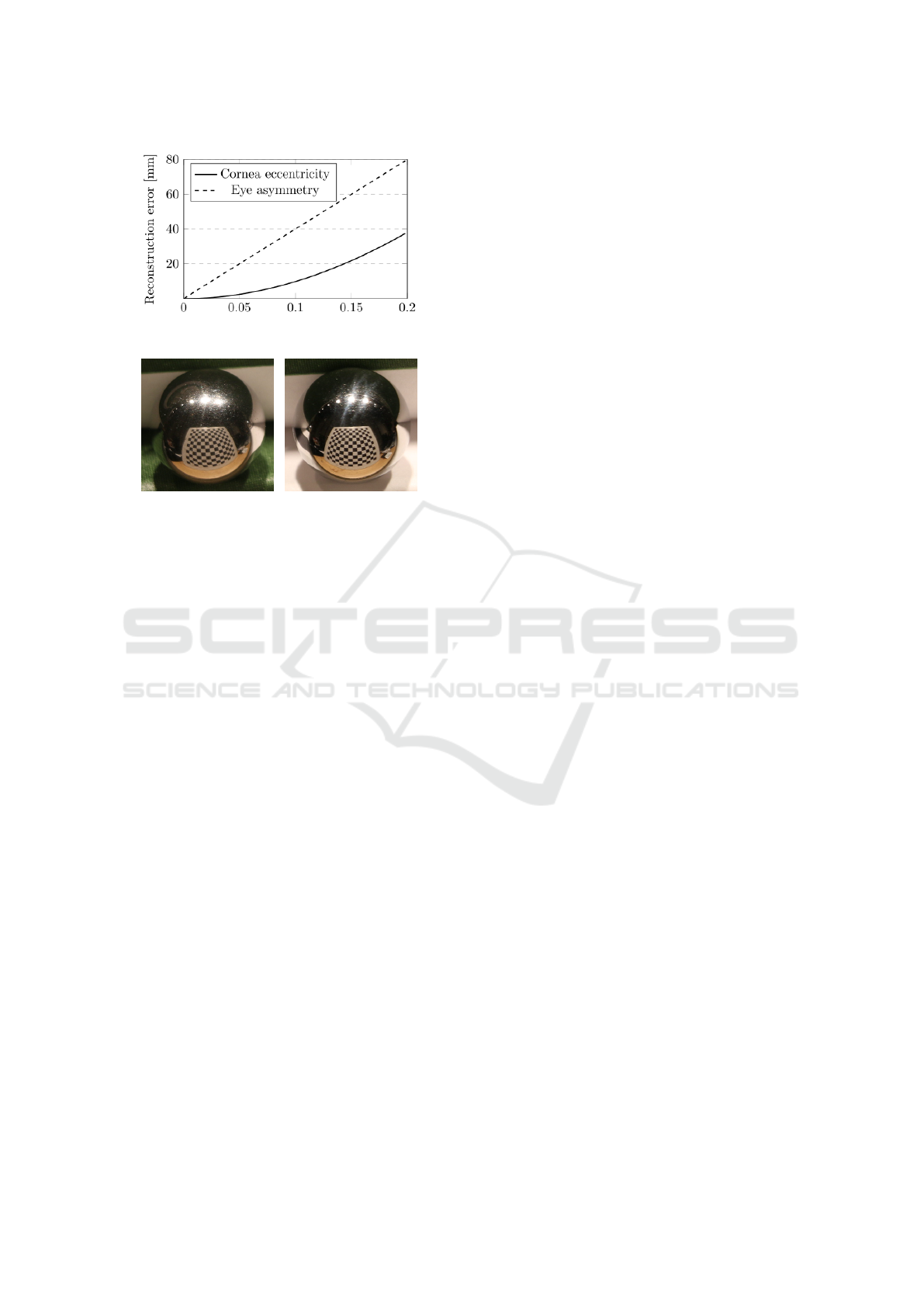
Figure 13: Reconstruction error analysis.
Figure 14: Steel ball catadioptric system, for comparison.
soid. For an eccentricity of 0.2, which corresponds
to a small/large ellipse axis ratio of 0.98, the recon-
struction error is 38 mm. The eye asymmetry is quan-
tified as the ratio of the radii of the left and right eye
corneal spheres. For an eye asymmetry of 10%, the
error is 40 mm. This analysis indicates that the recon-
struction error is quite sensitive to these two parame-
ters.
In our anatomy research review we did not find
a human population range for these parameters. We
experimented with extending our bundle adjustment
to optimize for eye asymmetry as well, but the repro-
jection errors did not decrease significantly. Further-
more, we have also investigated the validity of our as-
sumptions empirically, by reconstructing our scenes
from reflections captured from two high-grade steel
bearing balls of similar size to the human corneal sp-
heres (Figure 14). The bearing balls are truly spher-
ical and of equal size, so the bearing balls catadiop-
tric system satisfies all our assumptions. The recon-
structed scene accuracy was comparable to the recon-
structions from corneal reflections for the Checkerbo-
ard scene, which indicates indirectly that our corneal
catadioptric system assumptions are valid.
6 CONCLUSIONS AND FUTURE
WORK
We described a pipeline for extracting 3D scene struc-
ture from high resolution corneal reflections. The sy-
stem first calibrates the position of the eyes with re-
spect to the camera with subpixel accuracy, and then
uses the resulting catadioptric model to triangulate
corresponding corneal reflection features and pixels.
One limitation of the system stems from the as-
sumption that the input image provides a perfect cor-
neal reflection. Future work should take into account
the iris texture, which is a considerable source of
noise for light colored eyes. Methods for separating
the local from the global illumination (Nayar et al.,
2006) could be used to this effect. Another limita-
tion of the current pipeline implementation is that the
dense stereo stage relies on a naive patch color mat-
ching algorithm, which reduces the quality of the 3D
scene reconstruction. Our paper contributes a sub-
pixel accurate calibration of the corneal catadioptric
imaging system, which can be readily used with more
sophisticated stereo matching algorithms, such as for
example those that exploit scene geometry coherence
(Ohta and Kanade, 1985), (Sun et al., 2003), (Schar-
stein and Szeliski, 2002).
Another direction of future work is to accelerate
the pipeline to interactive performance, which allows
accumulating scene 3D structure over several frames,
or even from a video stream. A first step is to imple-
ment the dense stereo stage on a GPU. For a stationary
camera, the 3D points contributed by each frame are
already in a common coordinate system and can be
readily merged, without alignment.
Future work to extend our method beyond the lab
setting is challenging. Our work already reduces the
calibration error of the catadioptric system below one
pixel, which is an order of magnitude improvement
over prior art. But the inherent limitation that pre-
vents the reconstruction of scenes outside the lab is
the large distance from the eyes to the scene, relative
to the interpupillary distance and to the corneal re-
flection pixel resolution. Indeed, even for a 0.1 pixel
reprojection error, which is the standard for the cali-
bration error of simple optical systems with one ca-
mera, corneal reflection reconstructions will incur er-
rors of 6.33, 25.3, and 602mm at scene distances of 1,
2, and 10m, for a 5,472 x 3,648 resolution camera pla-
ced at 0.5m from the eyes. Our corneal catadioptric
system calibration and scene reconstruction pipeline
already achieves the best results afforded by the cur-
rent resolution of commercial digital cameras, further
improvements will have to come from increasing the
resolution of the corneal reflections.
Although images now have sufficient resolution
for direct display, giving the user the option to zoom
in on regions of interest, such as faces, and extracting
scene information from corneal and other fortuitous
reflections will continue to benefit from further incre-
ases of image resolution. Many of these applications
Subpixel Catadioptric Modeling of High Resolution Corneal Reflections
681

do not require high resolution throughout the image,
and a promising direction of future work in imaging
system design is to achieve a variable resolution over
the field of view. Although consumer-level devices,
such as phones, now have multiple cameras with vari-
ous focal lengths, achieving a high resolution at appli-
cation specified locations in the field of view remains
intractable. A more promising approach is to rely on
a high resolution sensor with a wide angle lens and
to read and save only the pixels needed, resulting in a
versatile imaging system that helps leveraging secon-
dary rays for scene acquisition.
REFERENCES
Agrawal, A., Taguchi, Y., and Ramalingam, S. (2010).
Analytical forward projection for axial non-central di-
optric and catadioptric cameras. Computer Vision–
ECCV 2010, pages 129–143.
Agrawal, A., Taguchi, Y., and Ramalingam, S. (2011).
Beyond alhazen’s problem: Analytical projection mo-
del for non-central catadioptric cameras with quadric
mirrors. In Computer Vision and Pattern Recogni-
tion (CVPR), 2011 IEEE Conference on, pages 2993–
3000. IEEE.
Bay, H., Tuytelaars, T., and Van Gool, L. (2006). Surf:
Speeded up robust features. In European conference
on computer vision, pages 404–417. Springer.
Calonder, M., Lepetit, V., Strecha, C., and Fua, P. (2010).
Brief: Binary robust independent elementary featu-
res. In European conference on computer vision, pa-
ges 778–792. Springer.
Conn, A. R., Gould, N. I., and Toint, P. L. (2000). Trust
region methods. SIAM.
Debevec, P. (2008). Rendering synthetic objects into real
scenes: Bridging traditional and image-based graphics
with global illumination and high dynamic range pho-
tography. In ACM SIGGRAPH 2008 classes, page 32.
ACM.
Dodgson, N. A. (2004). Variation and extrema of human in-
terpupillary distance. In Electronic imaging 2004, pa-
ges 36–46. International Society for Optics and Pho-
tonics.
Eberly, D. (2008). Computing a point of reflection on a
sphere.
Fasano, A., Callieri, M., Cignoni, P., and Scopigno, R.
(2003). Exploiting mirrors for laser stripe 3d scan-
ning. In 3-D Digital Imaging and Modeling, 2003.
3DIM 2003. Proceedings. Fourth International Con-
ference on, pages 243–250. IEEE.
Jenkins, R. and Kerr, C. (2013). Identifiable images of by-
standers extracted from corneal reflections. PloS one,
8(12):e83325.
Kassner, M., Patera, W., and Bulling, A. (2014). Pupil: an
open source platform for pervasive eye tracking and
mobile gaze-based interaction. In Proceedings of the
2014 ACM international joint conference on perva-
sive and ubiquitous computing: Adjunct publication,
pages 1151–1160. ACM.
Kuthirummal, S. and Nayar, S. K. (2006). Multiview ra-
dial catadioptric imaging for scene capture. In ACM
Transactions on Graphics (TOG), volume 25, pages
916–923. ACM.
Lienhart, R. and Maydt, J. (2002). An extended set of haar-
like features for rapid object detection. In Image Pro-
cessing. 2002. Proceedings. 2002 International Con-
ference on, volume 1, pages I–I. IEEE.
Lourakis, M. A. and Argyros, A. (2009). SBA: A Software
Package for Generic Sparse Bundle Adjustment. ACM
Trans. Math. Software, 36(1):1–30.
Lowe, D. G. (1999). Object recognition from local scale-
invariant features. In Computer vision, 1999. The pro-
ceedings of the seventh IEEE international conference
on, volume 2, pages 1150–1157. Ieee.
Mashige, K. (2013). A review of corneal diameter, curva-
ture and thickness values and influencing factors. Afri-
can Vision and Eye Health, 72(4):185–194.
Nayar, S. K. (1997). Catadioptric omnidirectional camera.
In Computer Vision and Pattern Recognition, 1997.
Proceedings., 1997 IEEE Computer Society Confe-
rence on, pages 482–488. IEEE.
Nayar, S. K., Krishnan, G., Grossberg, M. D., and Raskar,
R. (2006). Fast separation of direct and global com-
ponents of a scene using high frequency illumination.
In ACM Transactions on Graphics (TOG), volume 25,
pages 935–944. ACM.
Nishino, K. and Nayar, S. K. (2004). The world in an eye
[eye image interpretation]. In Computer Vision and
Pattern Recognition, 2004. CVPR 2004. Proceedings
of the 2004 IEEE Computer Society Conference on,
volume 1, pages I–I. IEEE.
Nishino, K. and Nayar, S. K. (2006). Corneal imaging sy-
stem: Environment from eyes. International Journal
of Computer Vision, 70(1):23–40.
Nitschke, C. and Nakazawa, A. (2012). Super-resolution
from corneal images. In BMVC, pages 1–12.
Nitschke, C., Nakazawa, A., and Takemura, H. (2011a).
Display-camera calibration using eye reflections and
geometry constraints. Computer Vision and Image
Understanding, 115(6):835–853.
Nitschke, C., Nakazawa, A., and Takemura, H. (2011b).
Image-based eye pose and reflection analysis for
advanced interaction techniques and scene under-
standing. Computer Vision and Image Media
(CVIM)(Doctoral Theses Session), pages 1–16.
Nitschke, C., Nakazawa, A., and Takemura, H. (2013). Cor-
neal imaging revisited: An overview of corneal re-
flection analysis and applications. IPSJ Transactions
on Computer Vision and Applications, 5:1–18.
Ohta, Y. and Kanade, T. (1985). Stereo by intra-and inter-
scanline search using dynamic programming. IEEE
Transactions on pattern analysis and machine intelli-
gence, (2):139–154.
Rockafellar, R. T. and Wets, R. J.-B. (2009). Variational
analysis, volume 317. Springer Science & Business
Media.
VISAPP 2019 - 14th International Conference on Computer Vision Theory and Applications
682

Rosten, E. and Drummond, T. (2006). Machine learning for
high-speed corner detection. In European conference
on computer vision, pages 430–443. Springer.
Scharstein, D. and Szeliski, R. (2002). A taxonomy and
evaluation of dense two-frame stereo correspondence
algorithms. International journal of computer vision,
47(1-3):7–42.
Schnieders, D., Fu, X., and Wong, K.-Y. K. (2010). Re-
construction of display and eyes from a single image.
In Computer Vision and Pattern Recognition (CVPR),
2010 IEEE Conference on, pages 1442–1449. IEEE.
Sun, J., Zheng, N.-N., and Shum, H.-Y. (2003). Stereo mat-
ching using belief propagation. IEEE Transactions on
pattern analysis and machine intelligence, 25(7):787–
800.
Viola, P. and Jones, M. (2001). Rapid object detection using
a boosted cascade of simple features. In Computer Vi-
sion and Pattern Recognition, 2001. CVPR 2001. Pro-
ceedings of the 2001 IEEE Computer Society Confe-
rence on, volume 1, pages I–I. IEEE.
Zhang, Z. (1999). Flexible camera calibration by viewing
a plane from unknown orientations. In Computer Vi-
sion, 1999. The Proceedings of the Seventh IEEE In-
ternational Conference on, volume 1, pages 666–673.
Ieee.
Subpixel Catadioptric Modeling of High Resolution Corneal Reflections
683
