
Photorealistic Reproduction with Anisotropic Reflection on Mobile
Devices using Densely Sampled Images
Shoichiro Mihara, Haruhisa Kato and Masaru Sugano
KDDI Research, Inc., Saitama, Japan
Keywords:
Photorealistic Reproduction, Augmented Reality, Image-based Rendering.
Abstract:
Photorealistic reproduction of real objects with complexities of geometry and optics on mobile devices has
been a long-standing challenge in augmented reality owing to the difficulties of modeling and rendering the
real object faithfully. Although image-based rendering, which does not require the objects to be modeled,
has been proposed, it still fails to photorealistically reproduce the object’s complete appearance containing
complex optical properties such as anisotropic reflection. We propose a novel system for use on mobile
devices capable of reproducing real objects photorealistically from all angles based on new view generation
using densely sampled images. In order to realize the proposed system, we developed a method of selecting the
image closest to a given camera view from densely sampled images by quantifying the similarity of two rays,
performed rigid geometric transformation to preserve the vertical direction for stable viewing, and introduced
color correction for consistency of color between the generated view and the real world. Through experiments,
we confirmed that our proposed system can reproduce real objects with complex optical properties more
photorealistically compared with conventional augmented reality.
1 INTRODUCTION
Applications designed to reproduce real objects have
become widespread throughout the market, especially
applications for mobile devices. For example, in
electronic commerce, applications for mobile devices
such as IKEA Place
1
are available that make it pos-
sible for the appearance of items to be observed as
if they were at hand by rendering them overlaid on a
real-world background; this is based on a technique
called augmented reality. However, the appearance
of the objects reproduced by these applications is not
photorealistic because they are not rendered based on
materials faithful to the original objects.
Modern rendering techniques can be classified
into two different categories; model-based render-
ing and image-based rendering (Levoy and Hanra-
han, 1996)(Gortler et al., 1996). As for model-
based rendering, the reflectance properties repre-
sented by a bidirectional reflectance distribution func-
tion (BRDF) is necessary to render objects photore-
alistically. However, to measure anisotropic BRDF
which arises from microstructures such as a hairline
processed metal or woven fabric, an expensive mea-
suring instrument and an enormous amount of mea-
suring time are required due to the need to observe
1
http://www.ikea.com/gb/en/customer-service/ikea-
apps/
light reflected at the object surface in all directions.
Image-based rendering that does not rely on geomet-
ric representation has been proposed to reproduce real
objects or scenes by synthesizing virtual views from
arbitrary camera positions using densely sampled im-
ages from a real or virtual environment. Although
it is a technique powerful enough to reproduce high-
quality virtual views, it still fails to photorealistically
reproduce the complete appearance containing com-
plex optical properties such as anisotropic reflection
because it is essentially based on interpolation of dis-
cretely sampled images which can miss capturing pro-
nounced variations in anisotropic reflection, which is
highly sensitive to viewing direction.
In this research, we propose a novel system for
use on mobile devices that can reproduce real ob-
jects photorealistically by generating new views from
all angles using densely sampled images. Our pro-
posed system can be utilized for various applications:
for example, examining unique cultural assets or rare
minerals for educational purposes, viewing items sold
on online shopping sites, and enjoying a realistic vir-
tual world for entertainment. The proposed system
has three main advantages. First, as with image-
based rendering, it can reproduce objects photoreal-
istically without constructing a geometric represen-
tation. Second, our proposed system can be easily
implemented and run on mobile devices with meager
Mihara, S., Kato, H. and Sugano, M.
Photorealistic Reproduction with Anisotropic Reflection on Mobile Devices using Densely Sampled Images.
DOI: 10.5220/0007342202170227
In Proceedings of the 14th International Joint Conference on Computer Vision, Imaging and Computer Graphics Theory and Applications (VISIGRAPP 2019), pages 217-227
ISBN: 978-989-758-354-4
Copyright
c
2019 by SCITEPRESS – Science and Technology Publications, Lda. All rights reserved
217
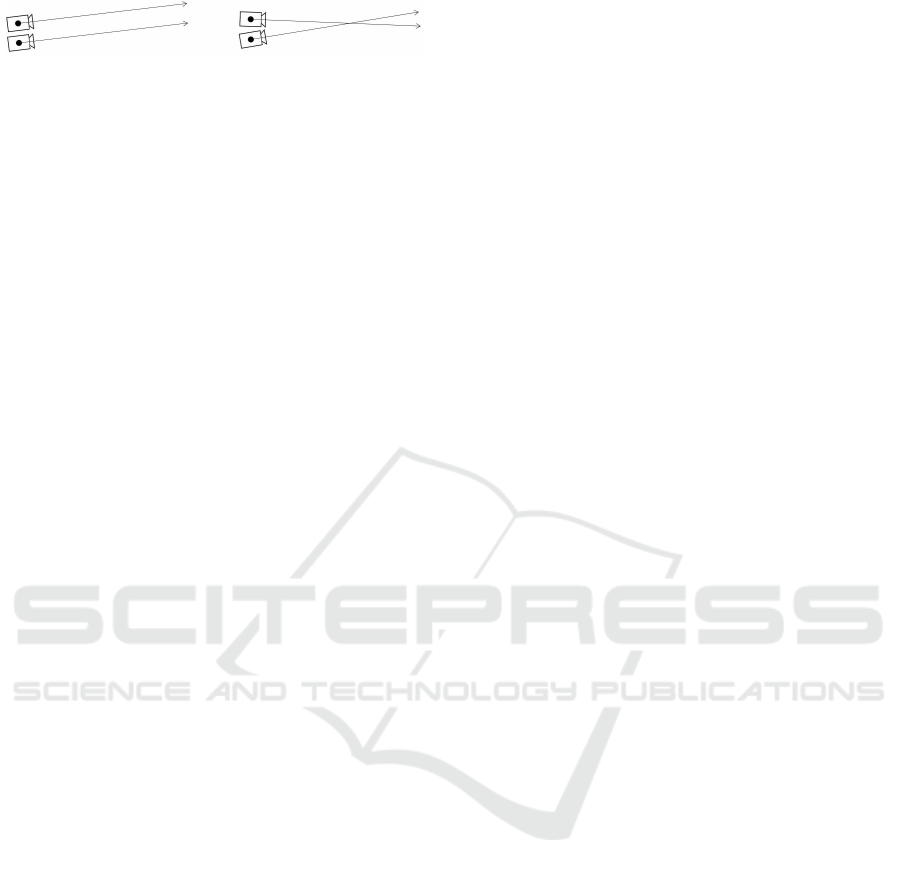
Figure 1: Problem of defining the similarity of camera poses
equivalent to rays. Which one is closer to each other?
computational resources, because it depends on sim-
ple manipulation of 2D-images. Third, the direction
of generated view is not limited to object-centered di-
rection, whereas image-based rendering implicitly as-
sumes that the camera always faces objects. That is
owing to our proposed method of quantifying the sim-
ilarity of the position and orientation of the cameras
(referred to as camera poses). It is problematic to de-
fine the similarity of camera poses due to differences
in unit and range, which is equivalent to defining the
similarity of two rays as shown in Fig. 1. Because this
problem has not been sufficiently studied to date, we
address it in this research.
In order to realize the proposed system, we sug-
gest several methods described in following contribu-
tions and introduce the color correction method for
consistency of color between the generated view and
the real world. Our major technical contributions are:
1. We propose a novel system to be run on mobile
devices that has been designed to reproduce ob-
jects photorealistically from all angles. (Section 3)
2. We propose a unique method of selecting the im-
age closest to a given camera view from densely
sampled images by quantifying the similarity of
two rays. (Section 3.1)
3. We propose a well-designed rigid geometric trans-
formation preserving the vertical direction for sta-
ble viewing. This is achieved by performingtrans-
lation, rotation, and scaling sequentially. (Sec-
tion 3.2)
This paper explains the proposed methods and shows
how the proposed system improves the reality of
the displayed objects by conducting experiments in
which we compare the results of the proposed system
with conventional augmented reality.
2 RELATED WORK
The simplest way to measure the BRDF is using a
gonioreflectometer (Nicodemus et al., 1977). But a
vast amount of measurement time is required since
the BRDF is measured with all combinations of the
incident and reflection directions by moving the light
source and the sensors. Therefore, studies on how
to improve BRDF measurement efficiency have been
conducted (Mukaigawa et al., 2009)(Tunwattanapong
et al., 2013)(Ward et al., 2014). Although it becomes
possible to measure BRDF that is not spatially uni-
form in a 3D shape within a relativelyshort time, there
are still the limitations, for example, the inability to
measure translucent objects and objects with concave
surfaces.
An image-based rendering technique relies on
densely sampled images and can be classified into
two fundamentally different approaches. The first ap-
proach is based on the concept of light field (Levoy
and Hanrahan, 1996)(Gortler et al., 1996). It repre-
sents the light ray as a 4D function of position and
direction, constructed with densely sampled images.
Virtual views from arbitrary camera positions can be
synthesized by extracting slices from the light field
and interpolating rays in an appropriate way. The
second approach is based on estimating the approx-
imate geometry in the form of depth maps (Shade
et al., 1998)(Sinha et al., 2012). Some sampled im-
ages are chosen based on the virtual camera position,
warped using the depth maps, and combined for new
view synthesis. An important advantage of these ap-
proaches is that they can synthesize photorealistic vir-
tual views with no or very little geometry informa-
tion and no explicit representation of optical prop-
erties of the objects. However, if their techniques
are applied to the reproduction of complex optical
properties which vary considerably depending on the
viewing angle, such as anisotropic reflection, undesir-
able artifacts of blurring and edge ghosting will oc-
cur. This is because image-based rendering is essen-
tially based on interpolation of discretely sampled im-
ages, even though some variants have been proposed
to increase realism of the rendered views (Wood
et al., 2000)(Shum et al., 2004)(Vagharshakyan et al.,
2015). Consequently, as we assume that target objects
have some complex optical properties as mentioned
above, we purposely do not depend on interpolation
techniques derived from image-based rendering. In-
stead we propose simple manipulation of 2D-images
which can produce acceptable results for our assumed
applications described in Section 5.
Photo-based augmented reality which reproduces
objects using densely sampled images has been pro-
posed by Ohta et al. (Ohta et al., 2012). This approach
is based on a kind of view-dependent texture map-
ping (Debevecet al., 1996). It has the same advantage
as image-based rendering which is able to reproduce
objects efficiently and photorealistically without a 3D
model. In addition, they proposed adding a method to
correct the difference in color tone between the sam-
pled images and the real environment (Ohta et al.,
2013). However, there is a problem that the repro-
duced objects appear to be unnatural as they do with
GRAPP 2019 - 14th International Conference on Computer Graphics Theory and Applications
218

Figure 2: Conceptual diagram of the proposed system.
conventional augmented reality because only the ob-
ject image is superimposed on the background of the
real environment and global illumination effects like
shadowing and interreflection between the object and
the surroundings cannot be reproduced.
Meanwhile, Suzuki et al. proposed a substitutional
reality that convinces the user that he/she is perceiv-
ing a live reality instead of another reality (or past re-
ality) by showing the user a movie taken in the past
without the user noticing a reality gap (Suzuki et al.,
2012). By switching between the real-world video ob-
tained from the camera mounted on the HMD worn
by the user and the video recorded at the same place
in the past alternately without the user being aware
of it, there arises a state in which the user mistak-
enly perceives the recorded video as the real world.
The limitation of their system is that the user’s view-
point must be fixed at the place where the video was
recorded. Although their research aimed at psycho-
logically verifying the concept of substitutional real-
ity, it is also applicable to augmented reality in that it
employs a phenomenon whereby past images are per-
ceived as the live reality, and our proposed system is
inspired by substitutional reality.
We propose a novel system so that the reproduced
objects are perceived as if they exist in front of the
eyes, and which performs object reproduction by sub-
stituting the image generated with densely sampled
images without estimating the explicit geometry of
the scene and BRDF of the target object.
3 PROPOSED SYSTEM
A conceptual diagram of the proposed system is
shown in Fig. 2. In an offline process, a collection
of images is sampled from all angles so that the ob-
ject to be reproduced (hereinafter referred to as the
target object) and the marker within the angle of view
are saved in the storage space along with the pose in-
formation, which is described in the next section. In
the online process, the user holds the mobile device
in front of his/her face, shoots the marker with the
camera mounted on the device, and views the image
displayed on the screen from various angles. First, the
camera pose relative to the world coordinate system is
estimated based on the marker designed as described
in Section 3.3, the similarities of the pose information
between of the camera view and of every sampled im-
age are evaluated, and the sampled image correspond-
ing to the most similar pose is selected. Then, the
selected image undergoes rigid geometric transforma-
tion so that it can be seen from the camera pose. In the
color correction process, the difference in color tone
between the sampled images and the camera view is
corrected, and the processed image is displayed on
the screen of the device. Details of each process are
described below.
3.1 Image Selection by Quantifying a
Similarity of Camera Poses
In this section, we explain how to select the sam-
pled image based on the similarity of the camera
pose. Conventional image-based rendering assumes
that possible views face the object center and sam-
pled images are selected based on only the distance
between viewpoints, ignoring the direction of view.
However, our system is designed to be used on mo-
bile devices where the viewpoints and directions can
be easily changed. Therefore, our proposed method
should be able to select a correct image from the sam-
ple collection that matches the given camera pose in-
cluding the direction of view.
Coordinate transformations between the world co-
ordinate (X,Y, Z) and the camera coordinate (x, y, z)
are denoted as
[xyz]
T
= R [X Y Z]
T
+ t , (1)
where t is the translation vector and R is the rotation
matrix (Tsai, 1987). If we evaluate the similarity of
the camera poses as the collective difference of ts and
Rs, it is necessary to perform weighting to correct the
gap between the unit and range of these parameters.
However, appropriate weight depends on the scale of
t which can change during operation. Therefore, we
propose a method to quantify the similarity of camera
poses by expressing them as a six-dimensional quan-
tity representing the camera view ray.
First, the position of the target object in the
world coordinate system is defined as the target point
P
tar
(X
t
,Y
t
, Z
t
) by the user. Then, the foot of the per-
pendicular from the target point P
tar
to the visual line
extending from the camera viewpoint P
cam
(X
c
,Y
c
, Z
c
)
is defined as the gaze point P
gaz
(X
g
,Y
g
, Z
g
) as shown
in Fig. 3(a). When the translational vector t and rota-
tion matrix R of the camera are estimated, the coor-
Photorealistic Reproduction with Anisotropic Reflection on Mobile Devices using Densely Sampled Images
219
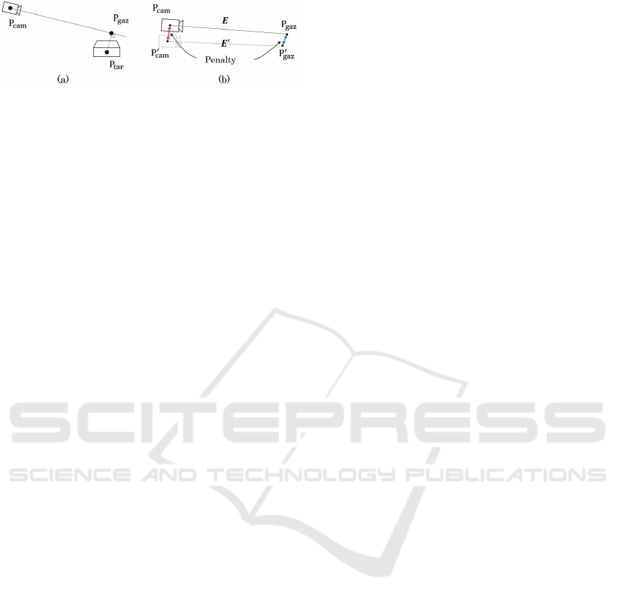
Figure 3: Conceptual diagram to explain how to define the
similarity of camera poses: (a) definition of object point and
gaze point; (b) penalty definition for evaluating similarity of
camera poses.
dinates of viewpoint P
cam
and gaze point P
gaz
can be
obtained from the following equations.
[X
c
Y
c
Z
c
]
T
= −R
T
t , (2)
X
g
Y
g
Z
g
T
= [X
c
Y
c
Z
c
]
T
+ e
T
R [X
tc
Y
tc
Z
tc
]
T
R
T
e ,
(3)
where [X
tc
Y
tc
Z
tc
]
T
= [X
c
− X
t
Y
c
−Y
t
Z
c
− Z
t
]
T
and e
is a unit vector of the visual line on the camera coor-
dinate system. Finally, the camera pose can be repre-
sented by combining (X
c
,Y
c
, Z
c
) and (X
g
,Y
g
, Z
g
) into
a six-dimensional quantity, defined as visual line seg-
ment E:
E ≡ (X
c
,Y
c
, Z
c
, X
g
,Y
g
, Z
g
) . (4)
The penalty of camera pose similarity is quanti-
fied by the Euclidean distance between E, which rep-
resents certain camera pose, and E
′
, which represents
another pose, as shown in Fig. 3(b). In the proposed
system, sampled images and visual line segments E
′
i
are stored in a storage space (i is an index of stored
images), and the index i
min
(t) of the visual line seg-
ment which most closely resembles the visual line
segment of the user camera E(t) is calculated at each
time t by
i
min
(t) = arg min
i
kE(t) − E
′
i
k
2
. (5)
When the penalty is small, the viewpoint and the
direction of the visual line approach one another and
the overlapping of the imaging ranges of the cameras
becomes larger. The remaining gap between views
corresponding to E(t) and E
′
i
min
(t)
is corrected by ge-
ometric transformation described in the next section.
3.2 Generation of Displayed Image by
Geometric Transformation
Because the sampled images are captured from dis-
crete camera poses, translation and orientation of the
image (referred to as image pose) selected by equa-
tion (5) may be different from the image pose of the
camera. In order to generate the new view, rigid ge-
ometric transformation is performed on the selected
image to correct the difference of image pose. In this
section, we propose a method of sequential similar-
ity transformation that can convert the image pose in
more stable condition while maintaining the object
shape.
3.2.1 Homography Transformation
As a naive method, homography transformation can
be performed to match the marker planes in the se-
lected image and the camera image to match their im-
age pose. However, when homography transforma-
tion between the planes is performed, the shape of the
three-dimensional object is deformed. This is not ac-
ceptable for the proposed system.
3.2.2 Similarity Transformation
To generate displayed images while maintaining the
object shape, similarity transformation can be used as
a naive method. Similarity transformations between
the image coordinates (x, y) and (x
′
, y
′
) are denoted
by the following equation.
x
y
1
=
scosθ −ssinθ t
x
ssinθ scosθ t
y
x
′
y
′
1
, (6)
where θ is the rotation angle, [t
x
t
y
]
T
is the translation
vector and s is the scale transformation in the image
plane. By using coordinates of corresponding points
based on the marker within the sampled image and
the camera view, the similarity transformation matrix
is estimated by the least squares method. However,
when the camera pose changes over time, all param-
eters of the matrix may fluctuate due to the estima-
tion error. Therefore, the view generated by similar-
ity transformation may make the image pose unstable,
givingthe user an unnatural impression. This problem
can be solved by sequential similarity transformation
as described below.
3.2.3 Sequential Similarity Transformation
Because the generated view of the proposed system is
viewed as if it is captured by the device’s camera, the
scale value s cannot be distinguished from the zoom
operation. To make the best use of this feature, we
propose a method of sequential similarity transforma-
tion to stabilize the image pose of the generated view
by removing the error fluctuation from the rotation
angle θ and the translation vector [t
x
t
y
]
T
and allow-
ing the error only on the scale value s, which can be
temporally smoothed.
First, the world landmark vector u
wld
is defined
as shown in Fig. 4 (how to define it is described at
GRAPP 2019 - 14th International Conference on Computer Graphics Theory and Applications
220
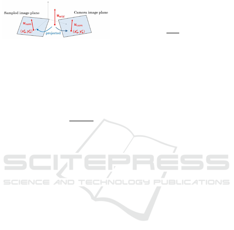
Figure 4: Conceptual diagram of world landmark vector and
projection to image planes (Note that the image planes are
actually closer).
the end of this section). Then, the vector u
wld
is pro-
jected to the camera image plane and the sampled im-
age plane, and let the projected vectors be u
cam
and
u
sam
respectively. The vector from the initial point
(x
s
u
, y
s
u
) of u
sam
to the initial point (x
c
u
, y
c
u
) of u
cam
is
defined as translation vector t
u
and the angle θ
u
be-
tween u
cam
and u
sam
are calculated:
t
u
= [x
c
u
y
c
u
]
T
− [x
s
u
y
s
u
]
T
, (7)
θ
u
= sgn(u
sam
× u
cam
)arccos(
u
sam
· u
cam
|u
sam
||u
cam
|
) , (8)
where the counterclockwise direction is positive.
Second, the sampled image is transformed se-
quentially with the translation vector t
u
, then rotation
is performed with the angle θ
u
around the initial point
(x
c
u
, y
c
u
) of u
cam
. Rotation matrix R
u
is obtained by
R
u
=
cosθ
u
−sinθ
u
x
c
u
(1− cosθ
u
) + y
c
u
sinθ
u
sinθ
u
cosθ
u
−x
c
u
sinθ
u
+ y
c
u
(1− cosθ
u
)
.
(9)
The scale value s
u
is estimated by the least squares
method, which matches the scale of the sampled im-
age to the camera view. Denoting the coordinates of
the corresponding point group based on the marker
within the camera image and the sampled image as
(x
c
j
, y
c
j
) and (x
s
j
, y
s
j
) respectively, the scale value fit-
ting (x
c
j
, y
c
j
) and the point group obtained by translat-
ing and rotating (x
s
j
, y
s
j
) using t
u
and R
u
is expressed
by the following equation
x
c
j
− x
c
u
y
c
j
− y
c
u
= s
u
R
u
x
s
j
y
s
j
1
+
t
u
0
−
x
c
u
y
c
u
.
(10)
Let b
c
and A
s
be the matrices composed of the verti-
cal vectors of the left and right side of equation (10)
of all the corresponding points respectively, the scale
value s
u
is calculated by the least squares method as
s
u
= (A
T
s
A
s
)
−1
A
T
s
b
c
. (11)
As mentioned above, the magnitude of the error of
s
u
cannot be distinguished from the zoom operation.
Hence, when the system runs over time, it is reason-
able to smooth s
u
(t) with parameter M to suppress the
fluctuation of the scale of the displayed image by cal-
culating
¯s
u
(t) =
1
M + 1
t
∑
k=t−M
s
u
(k) . (12)
Finally, the new view is generated by translating,
rotating, and scaling the selected sampled image se-
quentially with t
u
, R
u
and ¯s
u
. Additionally, we can
clip an appropriately sized central area from the gen-
erated view since there is an unmapped area at the
edge of it.
Next, how to define the world landmark vector
u
wld
is described below. Although u
wld
can be de-
fined as an arbitrary vector, a vector within the imag-
ing range of the camera image and the sampled im-
age is appropriate because sequential similarity trans-
formation is based on the position and orientation of
u
wld
projected onto both images. Furthermore, since
the proposed system assumes the target object is sta-
tionary, the object should seem to be stationary, or
standing upright. Because humans perceive some-
thing as upright if it is consistent with the direction
of gravity (Rock, 1974), it is expected that the object
would appear to be upright if the direction of gravity
in the generated view is aligned with the direction in
the camera view that is the actual direction of gravity.
Therefore, we define u
wld
as a vector parallel to the
direction of gravity, where the initial point is camera’s
gaze point P
gaz
.
3.3 Correction of Color Tone
Our proposed system generates new views entirely
from densely sampled images. Consequently, if the
illumination environment is different from that when
the sampled images were captured, the color tone of
the sampled images may appear unnatural. In or-
der to make the color tone of the generated views
compatible with the actual illumination, we introduce
the color correction method proposed by Reinhard et
al. (Reinhard et al., 2001). They matched the color
tone between images not by estimating ambient light
but by adjusting the statistical values (average and
standard deviation) of each color channel after con-
verting RGB color into lαβ color space (Ruderman
et al., 1998) that has a low correlation with each chan-
nel. Although colors under actual illumination are not
completely reproduced, we can take advantage of the
simplicity and effectiveness of their method.
In order to introduce the color correction method
into the proposed system, we use a colored marker
board as shown in Fig. 5. The marker group is gener-
ated by ArUco (Garrido-Jurado et al., 2014) and each
Photorealistic Reproduction with Anisotropic Reflection on Mobile Devices using Densely Sampled Images
221
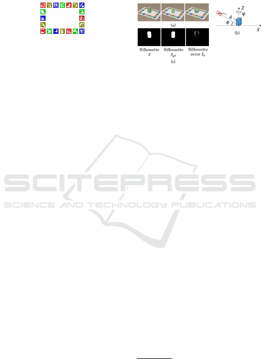
Figure 5: Colored marker board of the proposed system.
marker is painted arbitrarily with one of the RGB col-
ors of red(192, 0, 0), green(0, 192, 0), blue(0, 0, 192),
or yellow(128, 128, 0). Considering that the α and
β channels correspond to the complementary color
axes of yellow-blue and red-green respectively, the
marker’s colors are adjusted to ensure that the stan-
dard deviation of each channel is not too small and is
detectable by ArUco. The proposed system assumes
that the user looks at the generated view while captur-
ing the marker board of Fig. 5 and at least part of the
marker is within the angle of view of every sampled
image. Therefore, some of the same markers of the
colored marker board can be detected and identified
by ArUco in the selected image and the camera im-
age. Then, by matching the statistical values of lαβ
channels obtained from the pixel values in the color
reference area that is the internal area of the markers
identified in both the sampled image and the camera
image, it is possible to make the color tone of the gen-
erated view compatible with the actual illumination
environment.
Although we use the square fiducial marker in this
paper, we can also use any 2D images which have fea-
tures detectable with any well-known keypoint detec-
tor and descriptor (Rublee et al., 2011)(Alcantarilla
et al., 2013) as long as the color distribution of the im-
age is not too small such as that of a black-and-white
image. By dividing the image into several identifi-
able areas corresponding to each of the markers, we
can perform color correction in the same manner as
described above.
4 EXPERIMENTS
Using computer graphics simulation and a prototype
system, we conducted several experiments to validate
the effectiveness of the proposed system. We com-
pared the shape of the object in the virtual views gen-
erated by naive transformation and sequential simi-
larity transformation using computer graphics (Sec-
tion 4.1). Color correction is verified by application to
real images having several color tones (Section 4.2).
We then demonstrate that the proposed system can re-
produce the objects with anisotropic reflection or mi-
crostructures (Section 4.3). We conducted a subjec-
tive experiment to validate the capability of the pro-
Figure 6: Settings of evaluation experiment of sequential
similarity transformation: (a) example of sampled images;
(b) camera settings for generating the sampled images us-
ing computer graphics; (c) example of silhouette S, S
gt
and
silhouette error S
e
visualized as a binary image.
posed system to reproduce objects naturally and pho-
torealistically compared to conventional augmented
reality.
4.1 Evaluation of Sequential Similarity
Transformation
In order to verify how the shape of objects is dis-
played by sequential similarity transformation com-
pared with the other naive transformations, we con-
ducted the simulation experiment using computer
graphics. The sampled images are generated using
POV-Ray
2
, in which a solid primitive object, i.e., a
cuboid, cone, or sphere, is put on the colored marker
board and rendered with the camera settings as shown
in Fig. 6(a)(b). The gaze point is fixed at the cen-
ter of the marker board, distance to the gaze point is
fixed at d (= 6.0 in our experiment), the depression
angle φ is fixed at 30
◦
(actually, we incremented φ
by 10
◦
from 20
◦
to 70
◦
, but no different trend was
found in the results so we mention only 30
◦
for the
sake of simplicity), and the azimuth angle ψ is incre-
mented by 10
◦
. Then, 360 camera images are gen-
erated by rendering only the marker board with the
same camera settings except for the azimuth angle ψ
that is incremented by 1
◦
. The ground truth images
are generated by rendering the primitive object onto
each camera image. Using the sampled images and
the camera images, the virtual views are generated by
the proposed system based on homography transfor-
mation, similarity transformation, and sequential sim-
ilarity transformation (hereinafter referred to as Hom-
trans., Sim-trans., and Proposed-trans., respectively).
To compare the generated views between each trans-
formation, the silhouette S of the object is extracted.
Then, we define the difference between S and the sil-
houette S
gt
extracted from the ground truth image as
the silhouette error S
e
= S∪ S
gt
− S ∩ S
gt
, and n(S
e
) is
2
http://www.povray.org/
GRAPP 2019 - 14th International Conference on Computer Graphics Theory and Applications
222
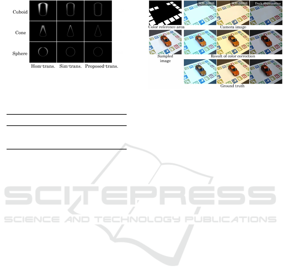
Figure 7: Comparison of the distribution of silhouette error
among Hom-trans., Sim-trans., and Proposed-trans.
Table 1: Average of n(S
e
) calculated from all views gen-
erated by Hom-trans., Sim-trans., and Proposed-trans. The
unit is pixel.
Cuboid Cone Sphere
Hom-trans. 2245.29 1471.35 1208.39
Sim-trans. 839.61 672.49 473.44
Proposed-trans. 521.71 317.58 290.59
calculated as an evaluation value that is the number of
pixels in S
e
. Fig. 6(c) shows an example of silhouette
S and S
gt
, and silhouette error S
e
.
We generated the views by Hom-trans., Sim-
trans., and Proposed-trans. for all camera images and
calculated silhouette errors S
e
, and evaluated the re-
sults with the average of n(S
e
) as shown in Table 1.
It can be seen that n(S
e
) of Proposed-trans. is smaller
than the other transformations. Additionally, Fig. 7
shows the distribution of the silhouette error S
e
visu-
alized by summing up S
e
assumed as binary images
and normalized to a range of [0, 255]. We can see
that the distribution of Proposed-trans. is narrower
than the other transformations. From the above re-
sults, we confirmed that by using Proposed-trans., the
displayed shape of an object was closest to the ground
truth and the position and orientation of the object
were maintained more stably compared with the other
transformations.
4.2 Evaluation of Color Correction
To verify how the color tones of the sampled im-
ages are converted by the color correction described
in Section 3.3, we conducted an experiment using real
images.
The colored marker board was printed on plain pa-
per and captured with the car model using a Logicool
web camera (C920) under a fluorescent lamp, setting
the white balance (WB) for a color temperature of
4000K. The captured image is used as the sampled
image as shown in Fig. 8 (middle-left). The images
captured from the same camera position with WB ad-
Figure 8: Experimental conditions and the results of
color correction: (top-left) color reference area for color
correction; (top-right) camera images (used as target
color); (middle-left) sampled image (used as source im-
age); (middle-right) results of color correction; (bottom-
right) ground truth.
justed to a color temperature of 2000K and 6500K and
under a dark illumination environment where some
fluorescent lamps were switched off (Fig. 8, bottom-
right) are used as ground truth. The images captur-
ing only the marker board by removing the car model
under each condition are used for the camera images
(Fig. 8, top-right). The color reference area is calcu-
lated as shown in the white area of Fig. 8 (top-left).
Then, color correction of the sampled image was per-
formed.
The results of color correction are shown in
Fig. 8 (middle-right). Comparing the camera images
with the results of color correction, it can be clearly
seen that their color tone corresponds closely. Fur-
thermore, when the results with the ground truths
are compared, we found that the color of the car
model is similar because the average color difference
in the CIELAB color space between the results and
the ground truths of each condition is (WB: 2000K)
11.2813, (WB: 6500K) 10.1238, and (dark illumina-
tion) 6.57909. Although we cannot claim that the
same color as the ground truth is reproduced because
there is a just noticeable difference in the CIELAB
color space of 2.3 (Sharma and Trussell, 1997), strict
color reproduction for user perception is outside the
scope of this paper since the generated view of the
proposed system is viewed through the display of a
mobile device with arbitrary color reproduction char-
acteristics.
4.3 Demonstration
In order to verify that the proposed system can dis-
play objects photorealistically even with anisotropic
reflection or microstructures that make them difficult
to render using computer graphics, we implemented
Photorealistic Reproduction with Anisotropic Reflection on Mobile Devices using Densely Sampled Images
223
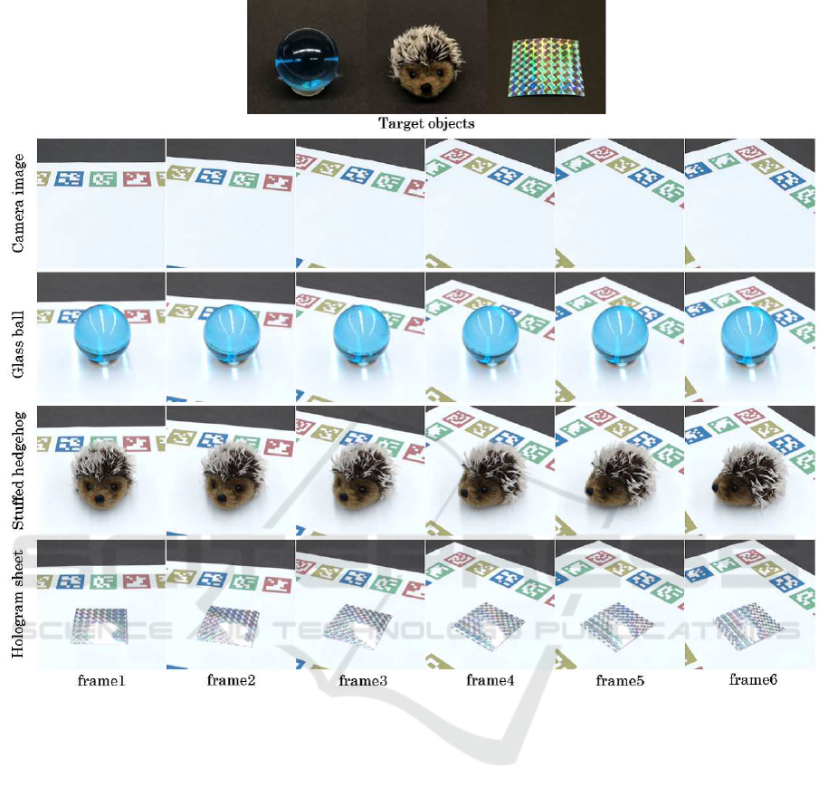
Figure 9: (Top) target objects; (bottom) sequences of the generated views of the proposed system for demonstration.
the prototype system on a PC and conducted a demon-
stration. Three objects as shown in Fig. 9 (top) are
used as targets: glass ball, stuffed hedgehog, and
hologram sheet. The target objects were placed on the
marker board, and we captured them manually from
all angles and stored the pictures as sampled images,
using a manual turntable to rotate objects and a tripod
to move the camera up and down. In our experimental
environment, the number of sampled images was re-
spectively 3741, 3442 and 3665 for each target object.
Fig. 9 (bottom) shows the sequences of the gener-
ated viewsof the proposed system (see supplementary
video for the entire sequences). Looking at the gener-
ated views of the glass ball and stuffed hedgehog, the
condensed light and the distorted background by the
glass ball can be seen naturally and the fluffy stuffed
hedgehog is faithfully reproduced, but it is difficult to
render with computer graphics. Also, looking at the
displayed images of the hologram sheet, we can see
how the color of the reflected light of the hologram
sheet changes depending on the viewing angle. Since
such anisotropic reflection requires considerable time
and cost for measurement (Ward et al., 2014), it is
difficult to create a 3D model and reproduce it with
conventional augmented reality.
4.4 Subjective Experiment
We conducted a subjective experiment to verify
whether the proposed system could display real ob-
jects more photorealistically than conventional aug-
mented reality. The target object was the car model
shown in Fig. 10(b) and 3747 sampled images were
captured manually in advance from all angles. The
proposed system was implemented on an ASUS
smartphone (Zenfone AR: CPU Snapdragon 821,
RAM 8 GB). The selected sampled image is read
from the storage (UFS 2.0) frame-by-frame and the
GRAPP 2019 - 14th International Conference on Computer Graphics Theory and Applications
224
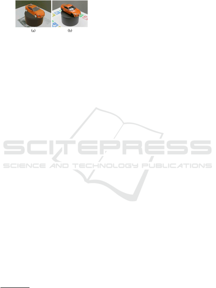
Figure 10: Example of the displayed image used in the sub-
jective experiment: (a) Conventional augmented reality; (b)
Proposed system.
frame rate was 6-7 fps in this environmentwith an im-
age size of 1280x720. A conventional augmented re-
ality application was implemented using Vuforia and
Unity to render the model of the same car provided
by SQUIR
3
as shown in Fig. 10(a), employing the
shader of Pro Car Paint Shader
4
available at Unity
Asset Store to present a realistic car model.
In the experiment, 19 participants aged from 25
to 59 years, some of whom had expertise in image
processing, were asked to view the display of the pro-
posed system and the conventional augmented reality
from various angles in any way they wished, and were
then asked to give their impressions of the display by
answering a questionnaire. The questions are shown
in Fig. 11. Q1 to Q5 are about the naturalness of the
displayed image, and Q6 and Q7 ask about the reality
and the presence of the target object. The response to
each question is evaluated on a 5-grade Likert scale.
The results of the questionnaire evaluation are also
shown in Fig. 11. The Wilcoxon signed-rank test was
performed and revealed a significant difference (p <
0.01) between groups for Q1, Q2, Q3 and Q7. From
these results, we can say that the proposed method
displays the color, reflection, shadow and shade more
naturally than conventional augmented reality. Fur-
thermore, the proposed method can present objects
more photorealistically than conventional augmented
reality. On the other hand, there is no significant dif-
ference between groups for Q4 and Q5 despite the
fact that the proposed system displays the object using
planar images that have undergone geometric trans-
formation. This result supports the effectiveness of
sequential similarity transformation.
Finally, we can find a weakly significant differ-
ence (p = 0.07) for Q6. This can probably be at-
tributed to the frame rate of the proposed system be-
ing considerably lower than conventional augmented
reality. While conventional augmented reality renders
smoothly at about 30 fps, the proposed system gen-
erates a partially jumpy displayed image at 6-7 fps
due to processing load and discontinuity of the sam-
pled images. Even though no one commented that
3
https://squir.com/
4
https://www.assetstoresales.com/
they felt the jumpy displayed image was unnatural,
the frame rate and the jumpy displayed image are is-
sues that need to be improved.
5 DISCUSSION
There are three major limitations of our system. First,
the sampling density and uniformity may crucially af-
fect the quality of generated views, although we con-
firmed that our system can present satisfactory new
views from sampled images created simply using a
manual turntable to rotate the objects and a tripod to
move the camera up and down. To address this, we
can introduce a view interpolation technique derived
from image-based rendering, and generate densely
and uniformly sampled images on the virtual sphere
covering the entire 3D object, employing the method
described by Chen and Rosenberg (Chen and Rosen-
berg, 2018). However, one of the difficult issues of
image-based rendering still remains, namely, unde-
sirable artifacts of blurring and edge ghosting. Fur-
thermore, the storage cost depends on the sampling
density (660MB in our subjective experiment) and it
is better to employ the data compression technique,
e.g. the method described by Ishigami et al. (Ishigami
et al., 2016), in practical use.
Second, if the visual marker is placed under
different lighting conditions, the highlights on the
displayed object and shadow/shade will be inconsis-
tent with the real-environment, which is an inherent
problem in sampling based methods including
image-based rendering, even though the differences
of brightness and color tone can be corrected by the
method described in Section 3.3. With that in mind,
we can provide two examples of application which
would not be affected by the above problem.
Reproduction of Cultural Assets in the Museum
In museums, the lighting environment is usually
fixed, and our system can be applied effectively to
exhibit cultural assets which are held in the museum’s
storage facility. It is impossible to exhibit thousands
of stored assets because space is limited, but once
images of them being exhibited have been captured,
they can be viewed as though they were on exhibition
at any time.
Item Browsing in an Electronic Commerce
In this case, the lighting environment at the time of
viewing is fundamentally different from the one at the
time of capturing. However, users are primarily inter-
Photorealistic Reproduction with Anisotropic Reflection on Mobile Devices using Densely Sampled Images
225

Figure 11: Questionnaire and participant’s answers represented as a box plot and the result of statistical analysis of the
subjective experiment.
ested in the feel of the item material, and users can
view the appearance of the items naturally with our
system even if the lighting environment reproduced
on the screen is different from the user’s environment.
Third, if another object come in the view of the
camera, the augmented reality experience of the pro-
posed system may be inhibited because the user is
looking at the offline sampled views with only think-
ing that it is augmented reality. If the region of
the interrupting object are extracted from the camera
view by the detection and segmentation technique (He
et al., 2017), the object can be superimposed in the
generated view of the proposed system. However the
occlusion culling is still difficult because it needs to
estimate the depth information from the single cam-
era view in real time.
6 CONCLUSIONS
In this research, we propose a novel system for use
on mobile devices capable of reproducing real ob-
jects photorealistically from all angles based on new
view generation using densely sampled images. In
order to realize the proposed system, we developed a
method of selecting the image closest to a given cam-
era view from densely sampled images by quantify-
ing the similarity of two rays, performed rigid geo-
metric transformation to preserve the vertical direc-
tion for stable viewing, and introduced color correc-
tion to maintain the consistency of color between the
generated view and the real world. We conducted
several experiments to verify the proposed methods
and confirmed that these methods worked effectively.
Then, we demonstrated that the proposed system can
reproduce objects with anisotropic reflection or mi-
crostructures using a prototype system. Finally, we
conducted a subjective experiment and validated that
the proposed system can reproduce objects naturally
and photorealistically compared to conventional aug-
mented reality.
In future work, we will attempt to speed up the
process using the technique of approximate nearest
neighbors search and introduce image interpolation
techniques to make the displayed images smoother.
REFERENCES
Alcantarilla, P., Nuevo, J., and Bartoli, A. (2013). Fast ex-
plicit diffusion for accelerated features in nonlinear
scale spaces. In Proceedings of the British Machine
Vision Conference. BMVA Press.
Chen, C. and Rosenberg, E. S. (2018). Virtual content cre-
ation using dynamic omnidirectional texture synthe-
sis. In 2018 IEEE Conference on Virtual Reality and
3D User Interfaces (VR), pages 1–2. IEEE.
Debevec, P. E., Taylor, C. J., and Malik, J. (1996). Mod-
eling and rendering architecture from photographs:
A hybrid geometry-and image-based approach. In
Proceedings of the 23rd annual conference on Com-
puter graphics and interactive techniques, pages 11–
20. ACM.
Garrido-Jurado, S., Mu˜noz-Salinas, R., Madrid-Cuevas,
F. J., and Mar´ın-Jim´enez, M. J. (2014). Auto-
matic generation and detection of highly reliable fidu-
cial markers under occlusion. Pattern Recognition,
47(6):2280–2292.
Gortler, S. J., Grzeszczuk, R., Szeliski, R., and Cohen, M. F.
(1996). The lumigraph. In Proceedings of the 23rd
annual conference on Computer graphics and inter-
active techniques, pages 43–54. ACM.
He, K., Gkioxari, G., Doll´ar, P., and Girshick, R. (2017).
Mask r-cnn. In Computer Vision (ICCV), 2017
IEEE International Conference on, pages 2980–2988.
IEEE.
Ishigami, F., Nagata, K., Ohta, M., and Yamashita, K.
(2016). Data compression for photo-based augmented
reality on a tablet. In Consumer Electronics, 2016
IEEE 5th Global Conference on, pages 1–2. IEEE.
Levoy, M. and Hanrahan, P. (1996). Light field rendering. In
Proceedings of the 23rd annual conference on Com-
GRAPP 2019 - 14th International Conference on Computer Graphics Theory and Applications
226

puter graphics and interactive techniques, pages 31–
42. ACM.
Mukaigawa, Y., Sumino, K., and Yagi, Y. (2009). Rapid
brdf measurement using an ellipsoidal mirror and a
projector. IPSJ Transactions on Computer Vision and
Applications, 1:21–32.
Nicodemus, F. E., Richmond, J. C., Hsia, J. J., Ginsberg,
I. W., and Limperis, T. (1977). Geometrical con-
siderations and nomenclature for reflectance, volume
160. US Department of Commerce, National Bureau
of Standards.
Ohta, M., Sato, T., Motokurumada, M., and Yamashita, K.
(2013). Real-time color correction for a photo-based
augmented reality system. In Consumer Electronics
(GCCE), 2013 IEEE 2nd Global Conference on, pages
102–103. IEEE.
Ohta, M., Yokomichi, R., Motokurumada, M., and Ya-
mashita, K. (2012). A photo-based augmented reality
system with html5/javascript. In Consumer Electron-
ics (GCCE), 2012 IEEE 1st Global Conference on,
pages 425–426. IEEE.
Reinhard, E., Adhikhmin, M., Gooch, B., and Shirley, P.
(2001). Color transfer between images. IEEE Com-
puter graphics and applications, 21(5):34–41.
Rock, I. (1974). The effect of retinal and phenomenal orien-
tation of the perception of form. Scientific American,
230(1):78–86.
Rublee, E., Rabaud, V., Konolige, K., and Bradski, G.
(2011). Orb: An efficient alternative to sift or surf.
In Computer Vision (ICCV), 2011 IEEE international
conference on, pages 2564–2571. IEEE.
Ruderman, D. L., Cronin, T. W., and Chiao, C.-C. (1998).
Statistics of cone responses to natural images: impli-
cations for visual coding. JOSA A, 15(8):2036–2045.
Shade, J., Gortler, S., He, L.-w., and Szeliski, R. (1998).
Layered depth images. In Proceedings of the 25th an-
nual conference on Computer graphics and interac-
tive techniques, pages 231–242. ACM.
Sharma, G. and Trussell, H. J. (1997). Digital color
imaging. IEEE Transactions on Image Processing,
6(7):901–932.
Shum, H.-Y., Sun, J., Yamazaki, S., Li, Y., and Tang, C.-K.
(2004). Pop-up light field: An interactive image-based
modeling and rendering system. ACM Transactions
on Graphics (TOG), 23(2):143–162.
Sinha, S. N., Kopf, J., Goesele, M., Scharstein, D., and
Szeliski, R. (2012). Image-based rendering for scenes
with reflections. ACM Trans. Graph., 31(4):100–1.
Suzuki, K., Wakisaka, S., and Fujii, N. (2012). Substitu-
tional reality system: a novel experimental platform
for experiencing alternative reality. Scientific reports,
2:srep00459.
Tsai, R. (1987). A versatile camera calibration technique
for high-accuracy 3d machine vision metrology using
off-the-shelf tv cameras and lenses. IEEE Journal on
Robotics and Automation, 3(4):323–344.
Tunwattanapong, B., Fyffe, G., Graham, P., Busch, J., Yu,
X., Ghosh, A., and Debevec, P. (2013). Acquiring
reflectance and shape from continuous spherical har-
monic illumination. ACM Transactions on graphics
(TOG), 32(4):109.
Vagharshakyan, S., Bregovic, R., and Gotchev, A. (2015).
Image based rendering technique via sparse represen-
tation in shearlet domain. In 2015 IEEE International
Conference on Image Processing (ICIP), pages 1379–
1383. IEEE.
Ward, G., Kurt, M., and Bonneel, N. (2014). Reducing
anisotropic bsdf measurement to common practice. In
Material Appearance Modeling, pages 5–8.
Wood, D. N., Azuma, D. I., Aldinger, K., Curless, B.,
Duchamp, T., Salesin, D. H., and Stuetzle, W. (2000).
Surface light fields for 3d photography. In Pro-
ceedings of the 27th annual conference on Computer
graphics and interactive techniques, pages 287–296.
ACM Press/Addison-Wesley Publishing Co.
Photorealistic Reproduction with Anisotropic Reflection on Mobile Devices using Densely Sampled Images
227
