
CAD-driven Pattern Recognition in Reverse Engineered Models
S. Gauthier
1,2
, W. Puech
1
, R. B
´
eni
`
ere
2
and G. Subsol
1
1
LIRMM Laboratory, CNRS, Univ. Montpellier, France
2
C4W, Montpellier, France
Keywords:
Reverse Engineering, Beautification, Geometric Constraints.
Abstract:
Today, it has become frequent and relatively easy to digitize the surface of 3D objects and then to reconstruct
a combination of geometric primitives such as planes, cylinders, spheres or cones. However, the given re-
construction contains only geometry, no information of a semantic nature used during the design process is
included. In this paper, we present a robust method to recognize specific geometric structures which are not
explicitly present in an object, such as features and repetitions. These are known as patterns, which are used
in the CAD modeling process. Moreover, the digitization of an object often leads to various inaccuracies,
and therefore inaccurate extracted primitives. We also demonstrate how recognized patterns can be useful as
an application in beautification, which consists of the adjustment of primitive parameters to satisfy geomet-
rical relations such as parallelism and concentricity. Our objective is to design a fast and automatic method,
which is seldom seen in reverse engineering. We show the efficiency and robustness of our method through
experimental results applied on reverse engineered 3D meshes.
1 INTRODUCTION
An industrial reverse engineering application aims to
reconstruct an object as a combination of geometric
primitives, from a digitized 3D mesh or a 3D point
cloud (B
´
eni
`
ere et al., 2013). For example, on manu-
factured objects, we search for planes, spheres, cylin-
ders, cones and tori. A more advanced objective of
the reverse engineering process may also be to re-
trieve the design intent of an object. To do this, we
must take into account CAD modeling rules, which
produce semantics in constructed objects.
In this paper, we propose a method to recognize
specific patterns from a set of primitives. This allows
us to deduce, even for an inaccurate digitized object,
geometrical relations given by the original modeling
process. Then, we show that these patterns can be
used to improve the reconstructed model, for exam-
ple. This is known as a beautification step (Langbein,
2003), which aims to satisfy the geometric relations
between the primitives (e.g. parallelism, orthogonal-
ity) by regularizing the primitive parameters.
We present previous work on this topic in
Section 2. Then, we detail our proposed method in
Section 3. Finally, we present experimental results
on several 3D meshes in Section 4 and conclude in
Section 5.
2 PREVIOUS WORK
During the design process of manufactured parts, par-
ticular geometric structures are often constructed ac-
cording to specific mechanical functions or machin-
ing processes. These structures are commonly called
patterns, and correspond to combinations of primi-
tives which respect some geometrical relations. In re-
verse engineering, recognizing these patterns allows
us to understand relations between the primitives and
to retrieve information about the design or the ma-
chining process of the part. In this section, we focus
on two types of patterns which are features and repe-
titions.
2.1 Feature Recognition
The first type of patterns contains neighboring prim-
itive subsets which define geometrical structures re-
lated to a machining process or a specific tool (Sanfil-
ippo and Borgo, 2016). These structures correspond
to features (Harik, 2007), which can be specific holes
for example. To recognize features, three approaches
seem to be favored (Babic et al., 2008). The first
one consists of the construction and an analysis of
a graph containing relations between the primitives,
which can be neighborhood (Lupinetti et al., 2017)
244
Gauthier, S., Puech, W., Bénière, R. and Subsol, G.
CAD-driven Pattern Recognition in Reverse Engineered Models.
DOI: 10.5220/0007360702440254
In Proceedings of the 14th International Joint Conference on Computer Vision, Imaging and Computer Graphics Theory and Applications (VISIGRAPP 2019), pages 244-254
ISBN: 978-989-758-354-4
Copyright
c
2019 by SCITEPRESS – Science and Technology Publications, Lda. All rights reserved

or geometric relations such as parallelism or concen-
tricity (Wu et al., 2003). Then, the pattern recogni-
tion corresponds to a sub-graph detection according
to each feature type. The second approach first de-
composes the part into small convex volumes, then
tries to detect specific volume combinations corre-
sponding to features (Geng et al., 2016). The third
approach groups other methods, which can be based
on hints such as 2D sections of the part for exam-
ple (Muraleedharan et al., 2018). Other methods have
been proposed to recognize patterns, based on neural
networks (Jun et al., 2001) or genetic algorithms (Pal
et al., 2005). However, these approaches require a
large and annotated database, which is out of our
scope. Finally, we highlight methods which use sys-
tems of rules based on three previously described ap-
proaches (Wang and Yu, 2014; Vilmart et al., 2018).
These rule systems can be used to infer new informa-
tion or construct a hierarchical system of features, for
example.
However, existing methods seem to have difficul-
ties correctly separating intersecting features. More-
over, some information used to recognize features are
specific to a feature type, which can be a problem
to extend the method to other features. On the other
hand, rule-based methods have been proposed to im-
prove obtained results, by taking the best of the three
approaches. In current literature, it seems that a few
methods propose to recognize features from primi-
tives extracted from a digitized 3D mesh, which are
often inaccurate. It would be interesting to adapt a
rule-based system and take into account all the infor-
mation deduced from both the 3D mesh and the ex-
tracted primitives.
2.2 Repetition Recognition
The second class of patterns contains repetitions from
a reference geometrical structure, such as a fea-
ture, which can be composed of one or many prim-
itives (Urbanic and Elmaraghy, 2008). This repetition
can then be constructed from a predefined scheme,
for example a line or a circle. The main particu-
larity of these patterns is that their components are
regularly spaced. For example, a circular repetition
places the reference feature duplicated regularly over
360
◦
. To recognize repetitions, a first approach con-
sists in the detection of transformation combinations
of a subset of primitives, such as translation, rotation
or scaling (Pauly et al., 2008). A second approach
is based on a symmetry detection, which allows us
to characterize a pattern by a combination of symme-
try planes (Vilmart et al., 2018). Other approaches
propose to use additional informations such as 2D
sections of the object for example (Urbanic and El-
maraghy, 2008). We note that most of the existing
methods only propose to recognize repetitions from
similar primitive subsets and define the extracted pat-
terns in a reference plane, as in standard CAD model-
ing processes.
However, most of these approaches are designed
for models without inaccuracies. In fact, similarity
and placement of inaccurate primitives are more com-
plex and can generate construction ambiguities, par-
ticularly when the complexity of the parts increases.
Therefore, it seems difficult to use existing methods
on reverse engineered models from inaccurate data in
a generic manner, without taking particular cases into
account.
3 PROPOSED PATTERN
RECOGNITION
In CAD modeling, we often construct some patterns
of primitives according to standard rules. In our con-
text, we need to recognize them from a combination
of geometric primitives. Firstly, we focus on neighbor
primitive sets, which can define features. Secondly,
we propose to recognize repetitions. In the context
of reverse engineering, we also propose an applica-
tion to model beautification (Langbein, 2003), which
regularizes primitive parameters with respect to geo-
metric constraints.
3.1 Feature Recognition
In mechanics, each part can correspond to a specific
function. When we focus on them more locally, we
can also find sub-parts which have their own func-
tions. We call these sub-parts features. These fea-
tures correspond to specific mechanical functions or
machining processes, and give some information con-
cerning geometrical relations between primitives. In
this work, we focus on two features, counterbored and
countersunk holes (see Fig. 1), which essentially im-
ply parallelism and concentricity relations. Since we
do not have any a priori information on the part, we
only analyze the geometry of these structures without
infering associated mechanical functions or machin-
ing processes. To recognize these features, we pro-
pose a rule-based method where the rules are defined
by geometrical relations between primitives. First, we
construct a graph which contains relations between
each pair of primitives: neighborhood, parallelism,
orthogonality and concentricity. Then, we define a
convexity relation between two primitives by analyz-
ing the convexity of their intersections. Finally, our
CAD-driven Pattern Recognition in Reverse Engineered Models
245
feature recognition process consists of extracting a
sub-graph respecting a set of specific rules for each
type of feature.
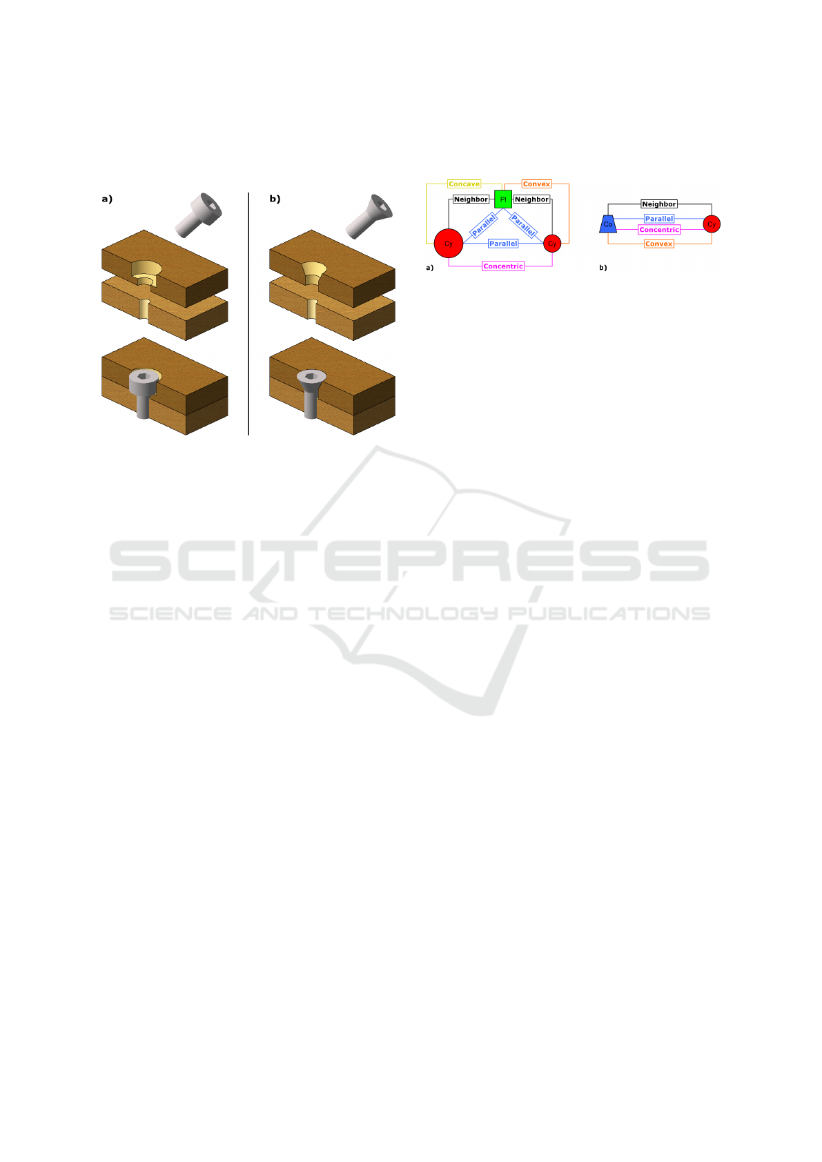
Figure 1: Focus on two features: a) Counterbored hole (or
counterbore), b) Countersunk hole (or countersink).
A counterbored hole, or counterbore, is a specific
type of drilling (Fig. 1.a). Its principal function is
to host and hide a flat head screw, a nut or a ring.
A counterbore is composed of: (i) a large cylinder
to host the screw head; (ii) a small cylinder to host
the screw thread; (iii) a plane to support the screw
head. Therefore, we define specific rules allowing us
to recognize the geometric structure of a counterbore
from a set of primitives and geometrical relations (see
Fig. 2.a): (i) the plane is a neighbor of the two cylin-
ders; (ii) the three primitives have parallel orienta-
tions; (iii) the two cylinders are concentric; (iv) the
two cylinders have different radii; (v) the intersection
between the plane and the small cylinder is convex;
(vi) the intersection between the plane and the large
cylinder is concave. A counterbore is then parameter-
ized by a position, an orientation, two radii, a drilling
depth and a counterbore depth. Its position is defined
as the intersection point between the plane and the
common axis of the two cylinders.
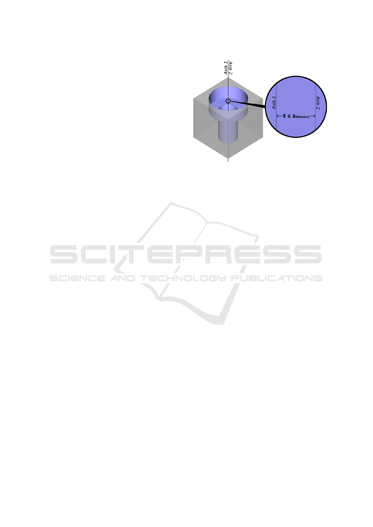
A countersunk hole, or countersink, is another
type of drilling (see Fig. 1.b). Its principal function
is to host and hide a tapered head screw. A counter-
sink is composed of: (i) a cone to host the screw head;
(ii) a cylinder to host the screw thread. Therefore, we
define a second set of rules, allowing us to recognize
the geometric structure of a countersink from prim-
itives and their relations (see Fig. 2.b): (i) the cone
and the cylinder are neighbors; (ii) the cone and the
cylinder are concentric; (iii) the intersection between
the cone and the cylinder is convex. A countersink
is then parameterized by a position, an orientation, a
radius, an angle, a drilling depth and a countersink-
ing depth. Its position is defined as the center of the
intersection circle between the cone and the cylinder.
Figure 2: Relation sub-graphs associated to features: a)
Counterbore, b) Countersink.
Therefore, each rule set defines a relation sub-
graph specific to a feature. The feature recognition
is then realized by searching for these specific sub-
graphs in a global relation graph between the primi-
tives.
3.2 Repetitions
In mechanical engineering, we often repeat features
along specific patterns. For example, aligning regu-
larly spaced fixing holes along a line can improve the
global fixation of a large part, increase the production
speed or reduce machining costs. Of course, these
repetitions can be constructed from varied sub-parts,
for economical or esthetic reasons. Consequently,
these repetitions contain semantic information, be-
yond the underlying geometry. In our approach, we
propose to recognize repetitions from a feature set.
Therefore, a repetition is defined by a set of simi-
lar features, regularly spaced along a specific pattern
such as a line or a circle. Unlike features, these rep-
etitions are not limited to neighboring components.
Then, this recognition allows us to determine relative
positions between features.
3.2.1 Feature Similarity
As explained before, a repetition groups similar fea-
tures. However, in the context of reverse engineer-
ing, the corresponding primitives can be inaccurate
since they are extracted from inaccurate data. Conse-
quently, we first need to define the similarity between
two features. To do that, we propose to compare their
parameters, according to predefined tolerances:
• ∆
distance
: distance tolerance defining two similar
positions;
• ∆
angle
: angle tolerance defining two similar orien-
tations.
Then, we define two types of similarity: partial and
integral. The partial similarity consists of the com-
parison of feature dimensions only. For example,
two counterbores are partially similar if their radii
GRAPP 2019 - 14th International Conference on Computer Graphics Theory and Applications
246
and depths are similar according to ∆
distance
. The
integral similarity consists in the comparison of di-
mensions with ∆
distance
and orientations with ∆
angle
.
Hence, integrally similar features are necessarily par-
allel. We note that partial similarity rules can be
adapted by adding or removing conditions, which al-
lows some flexibility in our method. This similar-
ity analysis compares all feature parameters except
their positions. Indeed, these can be defined relatively
when features are grouped in the same repetition.
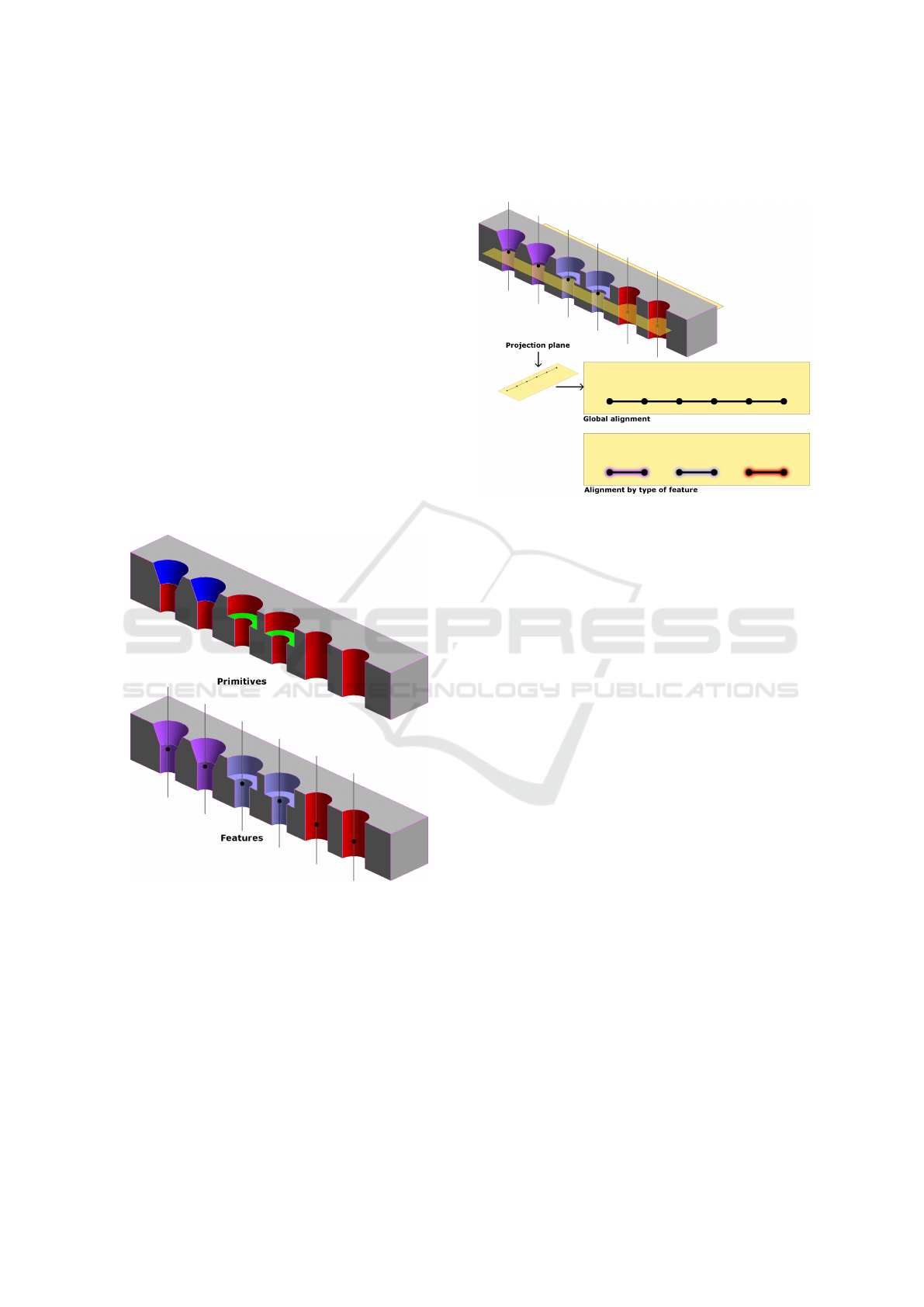
3.2.2 Alignment Detection
Linear repetitions, along a line, are most frequently
used in CAD modeling. To recognize linear repeti-
tions, we first need to detect aligned features. To do
this, we propose to extract a set of axes and points
directly from the feature parameters, as illustrated in
Fig. 3. In this example, we detect six aligned and par-
allel features: two countersinks, two counterbores and
two simple holes.
Figure 3: Axis and point extraction from feature parame-
ters. Each axis or point is then common to all the corre-
sponding primitives.
From these axes and points, it is possible to ex-
tract alignments in multiple directions. In CAD mod-
eling, repetitions are generally constructed from 2D
patterns, designed in a plane. From this observation,
we propose to detect repetitions in such planes. In the
case of parallel axes, we only use the plane which is
orthogonal to these axes, since it allows us to com-
pute orthogonal projection of feature positions. Our
feature alignment detection process is illustrated in
Fig. 4. We can distinguish two types of alignements:
global alignments using partial similarity rules and
alignments by type using integral similarity.
Figure 4: Axis and point alignments as 2D patterns in a
reference plane.
The proposed alignment detection consists of seven
steps.
1. Construct a plane P with a reference orientation
(according to coordinate system).
2. Project the feature positions {p
i
} on P , to obtain
the positions {p
0
i
}.
3. Construct a line D with a reference orientation
which is orthogonal to that of P .
4. Translate D on a position p
0
i
. This creates an
alignment A.
5. Add to A the positions {p
0
j
} that are a distance
δ 6 ∆
distance
from D.
6. Repeat these steps until all the planes, lines and
features are treated.
7. Keep only alignments of many features, then com-
pute the final alignment lines by a weighted aver-
age. The weights can be given by the area of each
feature.
Each alignment is then parameterized by a position,
a plane orientation, a line orientation and a feature
list. This algorithm retrieves global alignments, but
can be extended to alignments by types of features. To
do this, we can modify the fifth step to retrieve only
positions of the same type or apply integral similarity
rules.
3.2.3 Repetition Recognition
As described in Section 3.2.2, a repetition is an align-
ment of regularly spaced features that are similar.
CAD-driven Pattern Recognition in Reverse Engineered Models
247
In CAD modeling, repetitions are commonly con-
structed from five parameters: (i) a reference plane;
(ii) a 2D pattern belonging to the plane, which can
be a line or a circle for example; (iii) a reference
feature to repeat; (iv) an expected number of feature
copies; (v) the distance between two successive fea-
tures. To generalize the method, we propose to search
for combinations of repetitions, allowing us to recon-
struct complex feature configurations. For example,
a rectangular pattern can be defined as a combina-
tion of four repetitions or as a repetition of two sub-
repetitions (see Fig. 5).
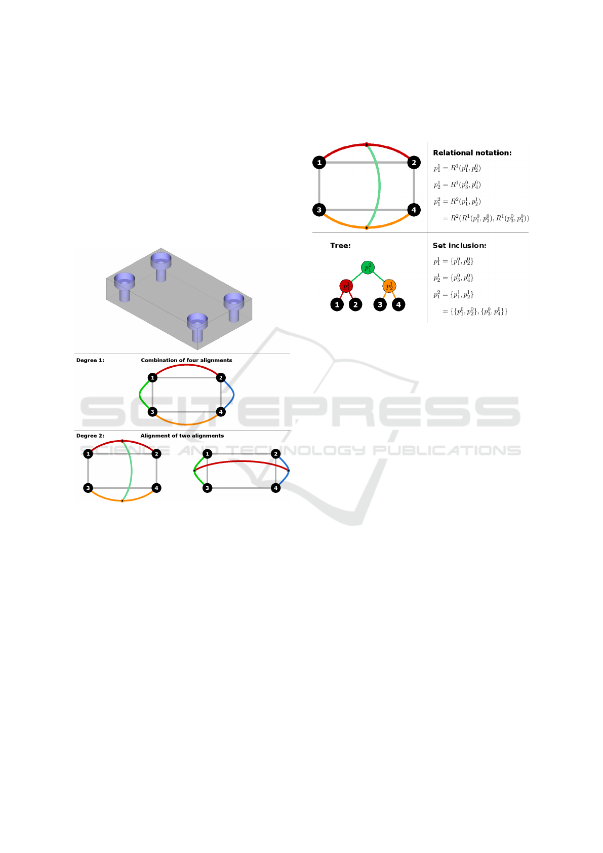
Figure 5: Three interpretations of a rectangular pattern.
Black disks correspond to features and colored curves cor-
respond to repetitions.
Therefore, we need to detect repetitions recur-
sively. We then define a new parameter, the degree,
which corresponds to the recursion depth needed to
construct a repetition. We propose to define a rep-
etition p
d
i
, where d corresponds to the degree, as a
relation R
d
between regularly aligned sub-repetitions
of lower degree:
p
d
i
= R
d
(p
d−1
1
... p
d−1
n
) with n > 2. (1)
In our approach, the sub-repetitions
{p
d−1
1
... p
d−1
n
} must be similar and regularly
spaced with a distance δ. The similarity between two
repetitions is then defined by comparing their param-
eters and those of their reference features. According
to the pattern type, other parameters need to be
compared such as orientations for a line or radii for a
circle. Here, a zero-degree repetition corresponds to
a feature. In the following, we could also represent a
repetition with a tree or a set inclusion (see Fig. 6).
Figure 6: Equivalent notations to represent a repetition.
From the rectangular pattern illustrated in Fig. 5,
with a length l and a width w, we can define
two equivalent two-degree repetitions: (i) by re-
peating according to l then w, we obtain the rep-
etition R
2
(R
1
(p
0
1
, p
0
2
), R
1
(p
0
3
, p
0
4
)); (ii) by repeating
according to w then l, we obtain the repetition
R
2
(R
1
(p
0
1
, p
0
3
), R
1
(p
0
2
, p
0
4
)). This equivalence between
repetitions can lead to identification problems. In-
deed, even if these repetitions result in the same final
primitive positions, we do not know which of them
was favored during modeling. Therefore, we propose
a decision algorithm to keep only the most relevant
repetitions. This algorithm is based on a set of prede-
fined rules, which allows for good adaptability. These
rules can be designed, for example, to maximize the
coverage of the object by repetitions or to reduce the
number and degree of repetitions. In our method, four
rules are defined to retrieve the most relevant repeti-
tions. These are based on successive minimizations
and maximizations of the repetition parameters:
1. maximize the total number of grouped features;
2. minimize the degree;
3. maximize the feature number of sub-repetitions;
4. minimize the distance between sub-repetitions.
The last two points are evaluated from a tree leaf,
which corresponds to the reference feature, then by
progressively tracing back to the root (see Fig. 7). We
note that only a subset of these rules can allow us to
decide which repetition to keep. For example, if two
repetitions do not contain the same total number of
features, the first rule is enough to select the most rel-
evant one. If the selection rules do not allow us to de-
GRAPP 2019 - 14th International Conference on Computer Graphics Theory and Applications
248
cide which repetition to keep, for example when they
have identical parameters as in the case of a squared
pattern, then one of the two repetitions is arbitrarily
chosen since it does not change the final results.
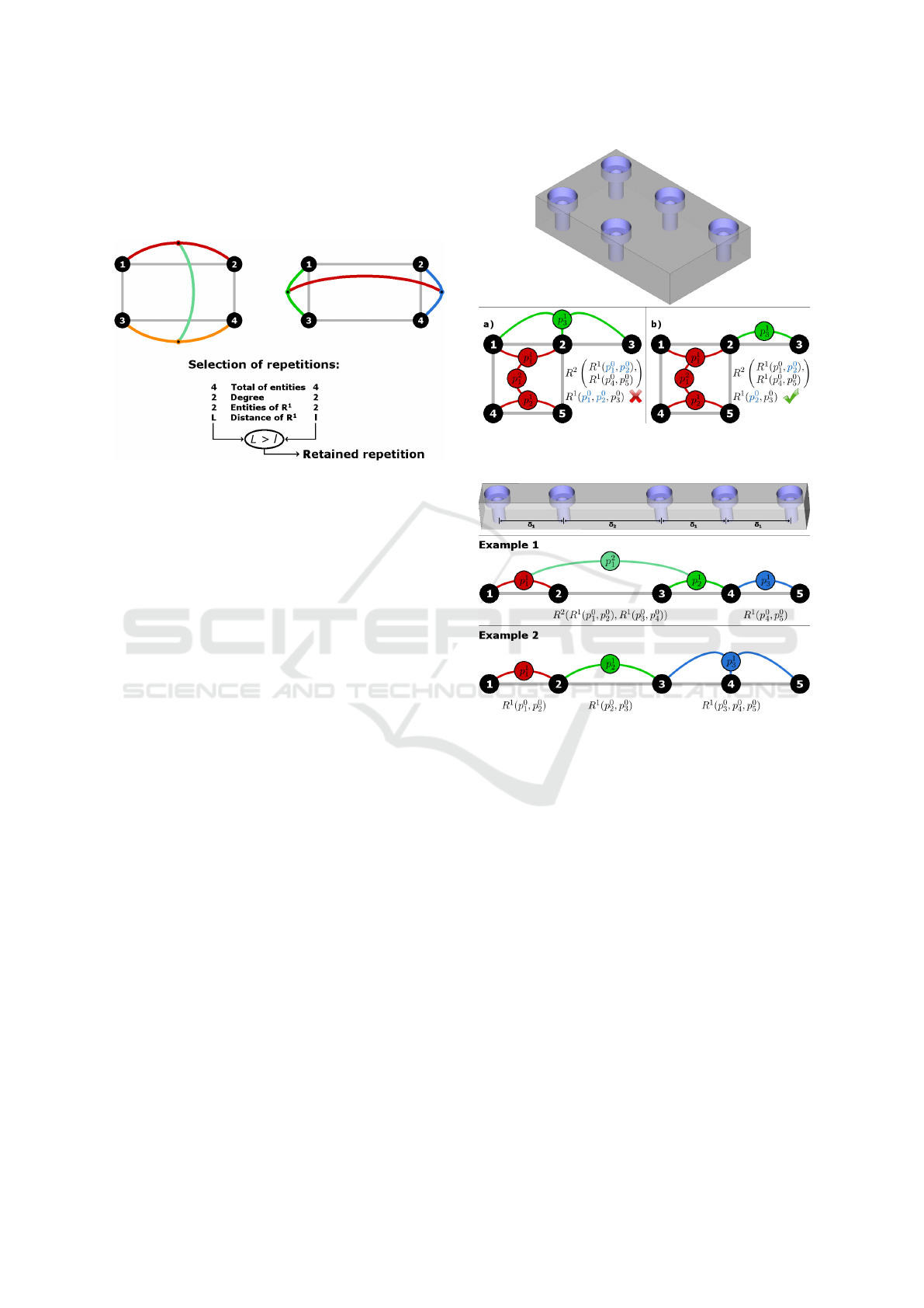
Figure 7: Selection of the most relevant repetition by com-
paring their parameters, according to predefined rules.
To better correspond to a CAD modeling process,
the selected repetitions must not have more than one
feature in common. If we take the example in Fig. 8.a,
two repetitions have been recognized, which means
that the object can be reconstructed in two steps. The
first step consists of the construction of the feature
p
0
1
, then repeating it four times to construct a squared
repetition p
2
1
. Secondly, the feature p
0
1
is repeated
along a line in three times, giving the linear repetition
p
1
3
. However, both these two repetitions construct the
feature p
0
2
whereas we must not construct the same
feature many times. Therefore, we need to remove
repetitions with more than one common features, and
keep at each step the most relevant one according to
our rules. This allows us to obtain the configuration
shown in Fig. 8.b, for example. This one consists
of the repetition of p
0
1
to construct a square, then to
repeat p
0
2
to construct p
0
3
. In this case, we obtain a
unique copy of each feature.
Besides this, some configurations can be ambigu-
ous or composed of many mixed patterns. In this
case, many repetition combinations can reconstruct
the same object. In Fig. 9, we can see two possible
repetition combinations allowing us to reconstruct the
same part. The first example is composed of a two-
degree and a one-degree repetitions. This combina-
tion seems to maximize the total number of grouped
features, and therefore seems to be the most relevant
one according to our four previously described rules.
The second example shows a combination of three
one-degree repetitions. This example seems to mini-
mize the repetition degree. To detect the second com-
bination, we only need to use the last three rules. This
highlights the adaptability of our algorithm.
Figure 8: Repetition overlap removal: a) Two common fea-
tures, b) One common feature.
Figure 9: Pattern example which can be described with dif-
ferent repetition combinations.
To correctly recognize repetitions according to
predefined rules, we need to take into account all pos-
sible combinations of the repetitions which allow us
to reconstruct the part. To do this, we propose an it-
erative algorithm (Algorithm 1). Firstly, we retrieve a
set of features {p
0
1
... p
0
n
}. Then, a feature p
0
1
is defined
as the reference feature in repetition recognition. We
then search for repetitions of two copies, three copies,
up to repetitions of n copies. This recognition is ap-
plied iteratively with each feature p
0
i
, to obtain all the
combinations. These define a set of one-degree repe-
titions {p
1
1
... p
1
k
}. The algorithm is iterated on these
one-degree repetitions, then on the obtained higher
degree repetitions {p
d
1
... p
d
n
}, until no new repetition
can be recognized. Finally, a selection step is applied
on all recognized repetitions to retain only the most
relevant combination. The theoretical complexity of
this algorithm can be relatively high, but according
to our observations, repetitions generally group small
numbers of features.
CAD-driven Pattern Recognition in Reverse Engineered Models
249
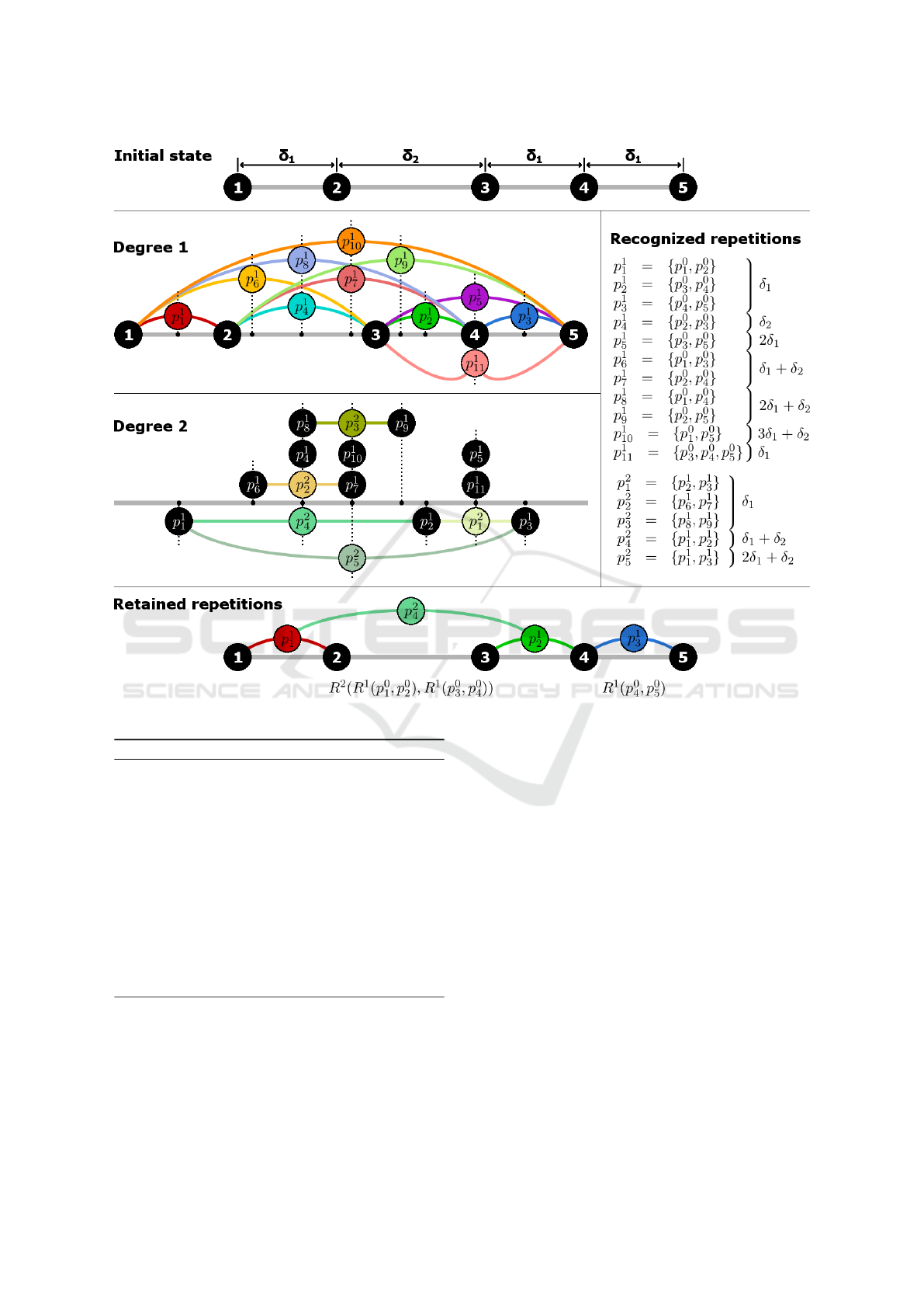
Figure 10: Recognition of all repetition combinations, for each degree, from the object illustrated in Fig. 9.
Algorithm 1: Recognition of repetitions combinations.
Input data: A set of features {p
0
1
... p
0
n
}
We define a set of repetitions R ← {p
0
1
... p
0
n
}
We define a repetition degree d ← 0
repeat
for all repetition p
d
i
∈ {p
d
1
... p
d
n
} ⊆ R do
for all number of copies m ∈ [2;n] do
R ← R ∪ Set of repetitions {p
d+1
1
... p
d+1
k
} com-
posed of m copies of p
d
i
end for
end for
d ← d + 1
until no new repetition can be recognized
R ← Selection of the most relevant repetitions from R
return R
Fig. 10 illustrates the progress of this algorithm
on the object from Fig. 9. During the one-degree
analysis, eleven repetitions are recognized, with only
one which contains three regularly spaced features.
During the two-degree analysis, five new repetitions
are recognized by grouping similar one-degree repe-
titions. No three-degree repetition are recognized so
the algorithm stops. Indeed, the detected two-degree
repetitions are not parameterized by similar distances,
and so cannot be grouped.
Finally, the relevant repetition selection analyzes
the sixteen obtained repetitions. Our first rule con-
sists of the maximization of the total number of fea-
tures included in each repetition. So, the algorithm re-
tains the repetitions {p
2
2
, p
2
3
, p
2
4
, p
2
5
}, which group four
features each. Our second rule does not allow us to
eliminate some of these, since they are all two-degree
repetitions. In the same way, our third rule also re-
tains these four repetitions since their sub-repetitions
group two features each. Our last rule compares the
distances between successive features, for each de-
gree. Firstly, the one-degree repetitions which min-
imize this distance are p
1
1
, p
1
2
and p
1
3
. Then, two-
degree repetitions are compared if they contain these
retained one-degree repetitions, i.e., p
2
4
and p
2
5
. Fi-
nally, the repetition p
2
4
minimizes the distance and so
is retained. During the second iteration, only the rep-
GRAPP 2019 - 14th International Conference on Computer Graphics Theory and Applications
250
etitions {p
1
3
, p
1
5
, p
1
9
, p
1
10
} do not have more than one
feature in common with p
2
4
. Again, the last rule,
which compares distances, allows us to retain the rep-
etition p
1
3
. The selection algorithm finally retains the
repetitions p
2
4
and p
1
3
, which corresponds to the first
combination example in Fig. 9.
In this example, we note that the repetition p
2
1
is
equivalent to the repetition p
1
11
. Indeed, these two
repetitions are parameterized by a unique distance δ
1
.
Moreover, the sub-repetitions of p
2
1
have a common
feature. This notion of equivalence could allow us,
for example, to reduce the algorithm complexity.
3.3 Application for Beautification
Pattern recognition groups together similar primi-
tives, features and repetitions. However, a reverse
engineering process generally approximates primi-
tive parameters from noisy data, such as digitized
3D meshes. In this case, data inaccuracies impact
these parameters which are then not exactly identi-
cal. Therefore, it seems appropriate to beautify the
reconstructed model, i.e., to regularize primitive and
pattern parameters.
3.3.1 Feature Regularization
As explained in Section 3.1, a feature is defined by
some parameters such as orientation, position and di-
mensions. However, the corresponding primitives can
be inaccurate. In this case, they do not exactly re-
spect the geometrical relations induced by the feature
design process. We note that in our work, we first
regularize orientation parameters to get exactly paral-
lel axes and simplify further analyses (see (Gauthier
et al., 2018)). For example, a counterbore can con-
tain two distinct axes, directly extracted from its two
cylinders which are approximatively concentric (see
Fig. 11). In this case, we need to correctly define the
feature parameters, especially when these parameters
are common to many primitives. In fact, a counter-
bore axis can be computed with a weighted mean of
two axes with weights corresponding to cylinder ar-
eas, for example. We compute a countersink axis in
the same way from its cylinder and its cone. The
other parameters of these two features are dimen-
sions, which are independant and can be directly ex-
tracted from the corresponding primitives. Finally,
feature parameters can be regularized according to
predefined modeling rules, for example. The corre-
sponding primitives are then regularized according to
the regularized feature.
Figure 11: Example of an inaccurate counterbore with two
distinct axes from its cylinders.
3.3.2 Repetition Regularization
As described in Section 3.2.3, a repetition is defined
by parameters such as a reference feature and the
distance between two successive features. However,
these parameters can also be impacted by inaccuracies
in primitive parameters (see Fig. 12). Indeed, a repe-
tition groups similar features, but not exactly identical
ones. Moreover, the distance between successive fea-
tures can vary when a repetition groups at least three
features. In this case, we need to correct the repetition
parameters. Therefore, the reference feature param-
eters can be regularized according to all the grouped
features, with a weighted mean, for example. Further-
more, the distance between successive features can be
computed from all the different distances contained in
the recognized repetition. Finally, repetition parame-
ters can be regularized according to predefined mod-
eling rules, for example. Then, the corresponding fea-
tures and primitives are made uniform according to
the regularized repetition.
4 EXPERIMENTAL RESULTS
In this section, we present experimental results con-
cerning our pattern recognition in reverse engineered
models. From complex digitized 3D point clouds or
3D meshes, a reverse engineering process extracts a
set of geometric primitives such as planes, cylinders,
cones and spheres. We then apply our pattern recog-
nition to this set of primitives.
In Fig. 13.a, we can see the Moldy object. From
this object, the reverse engineering process extracts
30 primitives (18 planes, 10 cylinders and 2 freeform
surfaces). As illustrated in Fig. 13.b, our process
extracts four features from these primitives. These
CAD-driven Pattern Recognition in Reverse Engineered Models
251
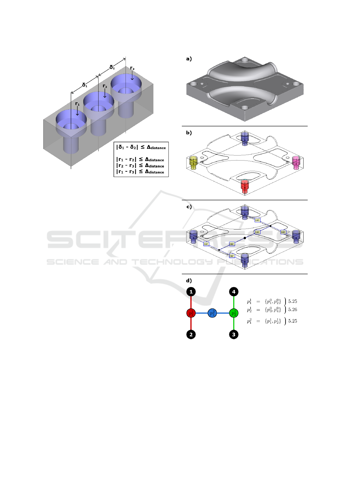
Figure 12: Example of an inaccurate repetition with a vari-
able distance between its features.
four features are parallel counterbores, each defined
by two radii and two depths. The four counterbores
are parameterized by a drilling radius of 0.187mm and
a chambering radius of 0.287mm. The correspond-
ing depths are respectively defined in the ranges of
[0.363;0.364] and [0.506; 0.508]. Since the four fea-
tures are similar, it is then possible to group them into
repetitions. The recognition and selection processes
give only one relevant repetition, with a degree of two
(see Fig. 13.c). This repetition consists in the align-
ment of two one-degree repetitions, which group two
counterbores each (see Fig. 13.d). We also notice that
these four counterbores are placed in a square pattern,
which certainly corresponds to the original design of
the part. Moreover, the center of the obtained repe-
tition is close to the center of the part, which allows
us to regularize the repetition position. Finally, all the
grouped primitives are regularized at the same time,
according to a unique parameter defining the length
of the side of the squared pattern. In this result, this
length seems to be equal to 5.25mm.
Fig. 14 shows our results on the Watertight ob-
ject, which is composed of 106 primitives (52 planes,
38 cylinders, 12 cones and 4 torii). This part con-
tains eight parallel counterbores (see Fig. 14.b). The
drilling radii are in the range of [4.95;4.97] and the
chambering radii are in the range of [6.59;6.96].
Concerning the depths, we find the ranges of
[10.23;10.47] and [12.27; 13.05]. Since the eight
counterbores are similar, two two-degree repetitions
are recognized. These repetitions group four coun-
terbores each, according to a rectangular pattern (see
Fig. 14.c). Fig. 14.d illustrates the obtained repeti-
tions with a schematic representation. The obtained
Figure 13: Features and repetitions extracted from Moldy
object: a) 3D object composed of 30 primitives, b) Features,
c) Repetitions, d) Schematic representation.
distance parameters suggest that these repetitions cor-
respond to two rectangles with a length of 82mm and
a width of 20mm. The grouped feature positions can
then be regularized according to the repetition centers
and distances. Moreover, we notice that the two rep-
etition centers are approximatively aligned with the
parts center, allowing us to regularize them.
However, these two repetitions are not grouped to-
GRAPP 2019 - 14th International Conference on Computer Graphics Theory and Applications
252
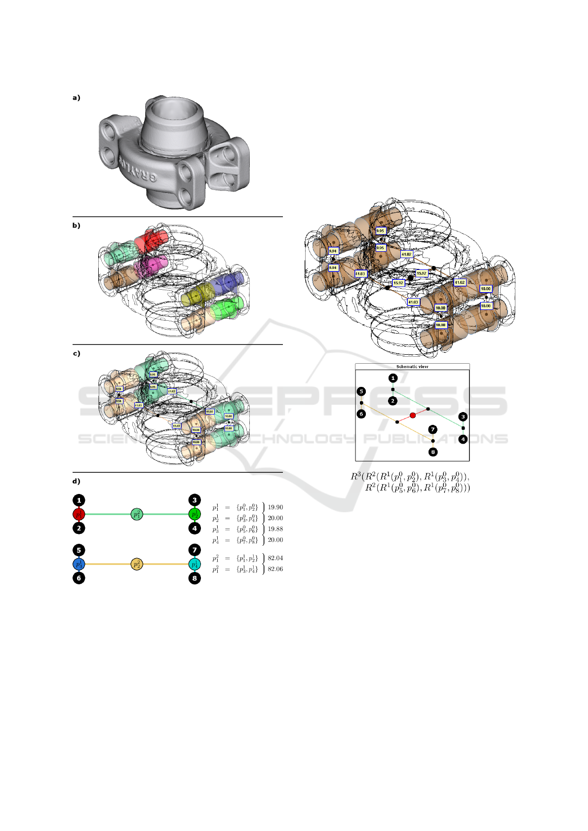
Figure 14: Features and repetitions extracted from Water-
tight object: a) 3D object composed of 106 primitives, b)
Features, c) Repetitions, d) Schematic representation.
gether, whereas they seem similar. Indeed, only their
orientation are different, and in this case they are anti-
collinear. In fact, it corresponds to a mirror-type de-
sign process, which consists in repeating a sub-part of
the object with a planar symmetry. We then propose
to adapt our repetition recognition rules to detect this
configuration. To do this, we just need to define a
new partial similarity rule, which allows us to detect
an orientation inversion. Finally, we obtain a three-
degree repetition, illustrated in Fig. 15. We note that
the center of this repetition is close to the center of the
part. In this case, we can regularize all the grouped
primitives according to the parts center and three dis-
tance parameters.
Figure 15: Mirror-type repetition recognized from repeti-
tions of Watertight object, which are illustrated in Fig. 14.
5 CONCLUSION
In this paper, an efficient method has been proposed
to analyze a set of geometric primitives and recognize
standard CAD patterns. We especially focus on two
types of patterns, these are features and repetitions.
We chose to work on primitives extracted from a dig-
itized 3D mesh, using a reverse engineering process.
The particularity of these primitives is that their pa-
rameters can be inaccurate. Indeed, fabrication and
digitization processes are not perfect, and can intro-
duce noisy data.
Our proposed pattern recognition allows us to de-
duce geometric relations and relative placement be-
tween inaccurate primitives. Then, we show that our
CAD-driven Pattern Recognition in Reverse Engineered Models
253

proposed analysis can be applied to a beautification
step, which consists of the regularization of primitive
parameters to better correspond to the original CAD
model. Our experimental results suggest that our ap-
proach is robust enough to analyze and correct primi-
tives from a complex digitized part.
Our proposed method is a first step towards a
fully automatic reverse engineering process, retriev-
ing the original design intent of a digitized manufac-
tured part. However, it can be difficult to take into
account all the primitive placement possibilities in
an object, i.e., all distances and proportions possibly
used during the modeling process. Therefore, our al-
gorithm is designed to be adaptive and easily exten-
sible, by adding or removing some rules concerning
geometrical relations, features and repetitions.
REFERENCES
Babic, B., Nesic, N., and Miljkovic, Z. (2008). A review of
automated feature recognition with rule-based pattern
recognition. Computers in Industry, 59(4):321–337.
B
´
eni
`
ere, R., Subsol, G., Gesqui
`
ere, G., Le Breton, F., and
Puech, W. (2013). A comprehensive process of re-
verse engineering from 3D meshes to CAD models.
Computer-Aided Design, 45(11):1382–1393.
Gauthier, S., Puech, W., B
´
eni
`
ere, R., and Subsol, G.
(2018). Orientation beautification of reverse engi-
neered model. In GRAPP: International Confer-
ence on Computer Graphics Theory and Applications,
pages 91–100.
Geng, W., Chen, Z., He, K., and Wu, Y. (2016). Feature
recognition and volume generation of uncut regions
for electrical discharge machining. Advances in Engi-
neering Software, 91:51–62.
Harik, R. (2007). Sp
´
ecifications de fonctions pour un
syst
`
eme d’aide
`
a la g
´
en
´
eration automatique de gamme
d’usinage: application aux pi
`
eces a
´
eronautiques de
structure, prototype logiciel dans le cadre du pro-
jet RNTL USIQUICK. PhD thesis, Universit
´
e Henri
Poincar
´
e-Nancy I.
Jun, Y., Raja, V., and Park, S. (2001). Geometric feature
recognition for reverse engineering using neural net-
works. The International Journal of Advanced Manu-
facturing Technology, 17(6):462–470.
Langbein, F. C. (2003). Beautification of reverse engineered
geometric models. PhD thesis, Cardiff University.
Lupinetti, K., Giannini, F., Monti, M., and Pernot, J.-P.
(2017). Identification of functional components in me-
chanical assemblies. Procedia CIRP, 60:542–547.
Muraleedharan, L. P., Kannan, S. S., Karve, A., and
Muthuganapathy, R. (2018). Random cutting plane
approach for identifying volumetric features in a CAD
mesh model. Computers & Graphics, 70:51–61.
Pal, P., Tigga, A., and Kumar, A. (2005). Feature extraction
from large CAD databases using genetic algorithm.
Computer-Aided Design, 37(5):545–558.
Pauly, M., Mitra, N. J., Wallner, J., Pottmann, H., and
Guibas, L. J. (2008). Discovering structural regular-
ity in 3D geometry. ACM transactions on graphics
(TOG), 27(3):43.
Sanfilippo, E. M. and Borgo, S. (2016). What are features?
An ontology-based review of the literature. Computer-
Aided Design, 80:9–18.
Urbanic, R. and Elmaraghy, W. (2008). Design recovery of
internal and external features for mechanical compo-
nents. Virtual and Physical Prototyping, 3(2):61–83.
Vilmart, H., L
´
eon, J.-C., and Ulliana, F. (2018). From
CAD assemblies toward knowledge-based assem-
blies using an intrinsic knowledge-based assembly
model. Computer-Aided Design and Applications,
15(3):300–317.
Wang, Q. and Yu, X. (2014). Ontology based automatic
feature recognition framework. Computers in Indus-
try, 65(7):1041–1052.
Wu, Y., Shah, J. J., and Davidson, J. K. (2003). Computer
modeling of geometric variations in mechanical parts
and assemblies. Journal of Computing and Informa-
tion Science in Engineering, 3(1):54–63.
GRAPP 2019 - 14th International Conference on Computer Graphics Theory and Applications
254
