
Object Detection, Classification and Localization by Infrastructural
Stereo Cameras
Christian Hofmann, Florian Particke, Markus Hiller and J
¨
orn Thielecke
Department of Electrical, Electronic and Communication Engineering, Information Technology,
Friedrich-Alexander-Universitat Erlangen-Nurnberg, Am Wolfsmantel 33, Erlangen, Germany
Keywords:
Object Detection, Infrastructural Cameras, Stereo Vision, Deep Learning, Autonomous Driving, Robotics.
Abstract:
In the future, autonomously driving vehicles have to navigate in challenging environments. In some situati-
ons, their perception capabilities are not able to generate a reliable overview of the environment, by reason
of occlusions. In this contribution, an infrastructural stereo camera system for environment perception is
proposed. Similar existing systems only detect moving objects by background subtraction algorithms and
monocular cameras. In contrast, the proposed approach fuses three different algorithms for object detection
and classification and uses stereo vision for object localization. The algorithmic concept is composed of a
background subtraction algorithm based on Gaussian Mixture Models, the convolutional neural network ”You
only look once” as well as a novel algorithm for detecting salient objects in depth maps. The combination
of these complementary object detection principles allows the reliable detection of dynamic as well as static
objects. An algorithm for fusing the results of the three object detection methods based on bounding boxes is
introduced. The proposed fusion algorithm for bounding boxes improves the detection results and provides an
information fusion. We evaluate the proposed concept on real word data. The object detection, classification
and localization in the real world scenario is investigated and discussed.
1 INTRODUCTION
State-of-the-art navigation of autonomous vehicles is
widely based on maps of static environments. In ad-
dition, the vehicle’s own environment perception ca-
pabilities are used for navigating. Outdated static en-
vironment maps and a perception with a very small
field of view lead to challenging navigation situati-
ons. An example is an autonomous car in a parking
garage, where also pedestrians move. In this environ-
ment the autonomous car is not able to detect and lo-
calize occluded objects like pedestrians and other ob-
stacles. Besides the difficult navigation, this limited
environment perception of the car results in dange-
rous situations for the pedestrians. To overcome such
problematic situations, we propose an infrastructural
stereo camera system that includes following novel
methods:
• An novel algorithm for detecting objects based on
depth maps
• Simultaneous use and fusion of three different ob-
ject detection algorithms
• Object localization based on stereo cameras
2 RELATED WORK
A variety of different approaches for detecting ob-
jects, mostly pedestrians, in parking garages have
been developed in the past. An approach for object
detection, localization and tracking in such environ-
ments based on mono cameras and a background sub-
traction algorithm is presented in (Ibisch et al., 2014)
and (Ibisch et al., 2015). A similar method is intro-
duced in (Einsiedler et al., 2014). Unlike these ap-
proaches, our solution uses multiple different object
detection methods and thus allows the detection of
dynamic as well as static objects. In (Kumar et al.,
2016) an approach using a convolutional neural net-
work (CNN) to obtain object classes is presented. The
authors introduce a camera system for parking gara-
ges, that evaluates image regions in which motion was
detected with a CNN for object classification. We
consider the simultaneous use of a CNN and a motion
detection algorithm as more advantageous. By simul-
taneous processing, also static objects can be detected
with the CNN. An overview of multiple vehicle ind-
oor positioning techniques including various types of
sensors is given in (Einsiedler et al., 2017).
808
Hofmann, C., Particke, F., Hiller, M. and Thielecke, J.
Object Detection, Classification and Localization by Infrastructural Stereo Cameras.
DOI: 10.5220/0007370408080815
In Proceedings of the 14th International Joint Conference on Computer Vision, Imaging and Computer Graphics Theory and Applications (VISIGRAPP 2019), pages 808-815
ISBN: 978-989-758-354-4
Copyright
c
2019 by SCITEPRESS – Science and Technology Publications, Lda. All rights reserved
3 PROPOSED APPROACH
Our approach for object detection, classification and
localization is based on the fusion of three algorithms.
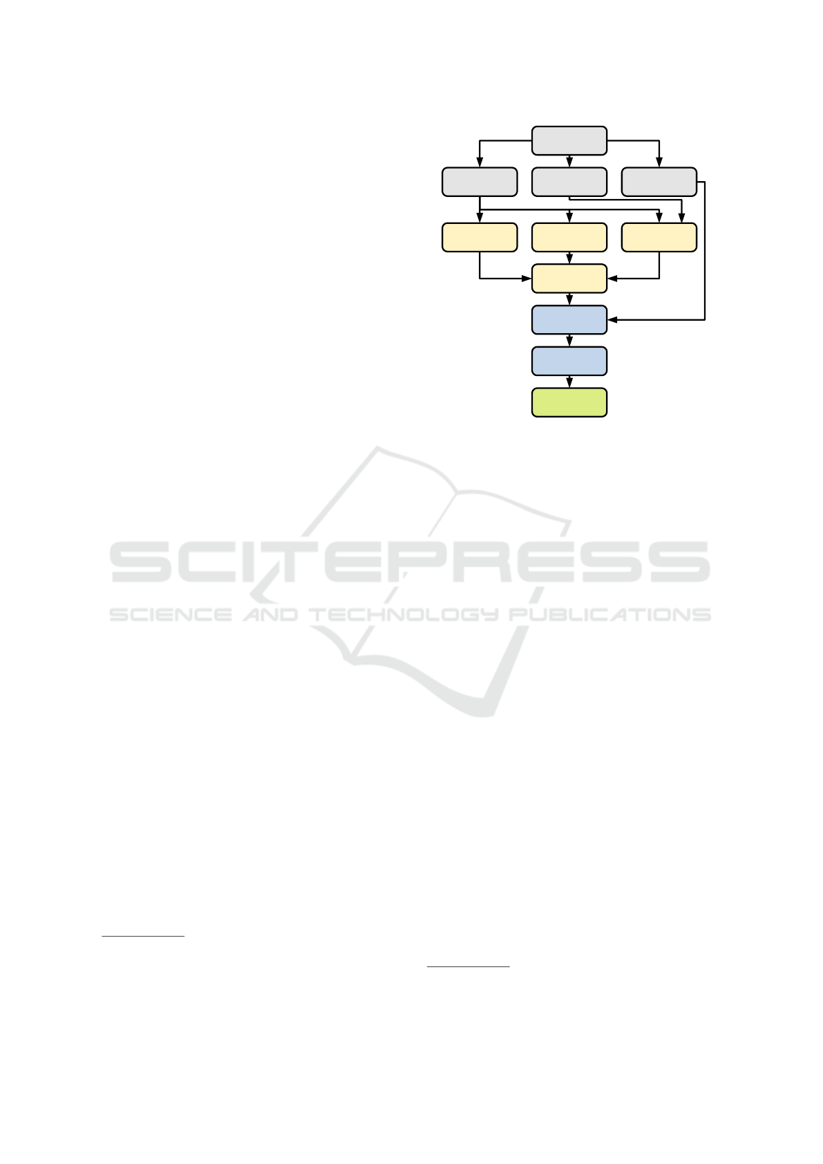
An overview is given in Figure 1. The stereo camera
provides a color image, a depth map and a point cloud
of the scene that is in its field of view. Following,
the color image and the depth map are simultaneously
processed by the three algorithms for object detection
and classification. These three methods are:
• You only look once (YOLO), a convolutional neu-
ral network (CNN)
• A background subtraction algorithm (further also
abbreviated BS)
• An novel algorithm for detecting salient objects in
depth images (further also abbreviated SO).
Further details concerning these three object detection
methods are described in the following section. The
object hypotheses, i.e., the detections of each algo-
rithm, are output in the form of bounding boxes. Sub-
sequently, the fusion of the detection results is based
on these boxes. The fusion algorithm is introduced
in Section 5. Following, the resulting object hypothe-
ses’ positions in the room (3D coordinates) are deter-
mined based on the point cloud and transferred into a
real-world metric coordinate system. This process is
specified in Section 6. As last step, the system publis-
hes the information about detected objects and their
positions via the ROS
1
framework.
Our proposed approach is running and evaluated
on a system composed of a ZED stereo camera
2
that
is connected to a Jetson TX2
3
computing platform.
4 OBJECT DETECTION AND
CLASSIFICATION
The use of multiple complementary object detection
approaches enables our system to create a complete
overview of the environment in its field of view.
Background subtraction algorithms are conside-
red to detect moving objects in images. We apply
the OpenCV
4
implementation of a background sub-
traction algorithm based on Gaussian Mixture Mo-
dels (Zivkovic, 2004; Zivkovic and Van Der Heijden,
2006). The results of the algorithm are post-processed
by applying Gaussian blur for noise reduction, mor-
phological closing and contour extraction. After-
1
http://www.ros.org/
2
https://www.stereolabs.com
3
https://www.nvidia.com
4
https://opencv.org/
Color image Depth map Point cloud
Stereo camera
Background
subtraction
YOLO Salient objects
Fusion
Localization
Coordinate
transformation
Publish
detections
Figure 1: Processing chain of the proposed system. The
stereo camera provides a color image, a depth map and a
point cloud. The color image and the depth map are used for
object detection and classification. The resulting detections
are fused. Afterwards, the object hypotheses are localized
and transformed to a real-world metric coordinate system.
Finally, the object hypotheses are published.
wards, bounding boxes enclosing the detections are
created. To receive only one bounding box per ob-
ject, a Non-Maximum-Suppression (NMS) algorithm
is applied, similar to (Zitnick and Doll
´
ar, 2014). In
contrast, we do not use the Intersection over Union
(IoU) as measure for deciding whether a box is sup-
pressed. Our approach checks if two bounding boxes
intersect. In case they do, the ratio of the intersecting
area to the area of the smaller box is computed. If this
ratio exceeds a threshold value, the smaller bounding
box is suppressed. The bigger bounding box is enlar-
ged, so that the smaller box would be enclosed by this
new bounding box. The reason for our modification
of the NMS is described in more detail in Section 5,
as similar principles apply to our fusion algorithm.
The CNN YOLO (Redmon et al., 2016; Redmon
and Farhadi, 2017) detects and classifies objects in
color images. Compared to the other two algorithms,
this neural network provides information about the
class of the detected object. However, it is only able
to detect previously trained object classes. In our sy-
stem, the tiny version of YOLOv2 (Tiny YOLO)
5
is
used, as the computation time per image is signifi-
cantly smaller on the Jetson TX2 compared to the
full version. We use pretrained weights based on the
COCO
6
dataset.
5
https://pjreddie.com/darknet/yolov2/
6
cocodataset.org
Object Detection, Classification and Localization by Infrastructural Stereo Cameras
809
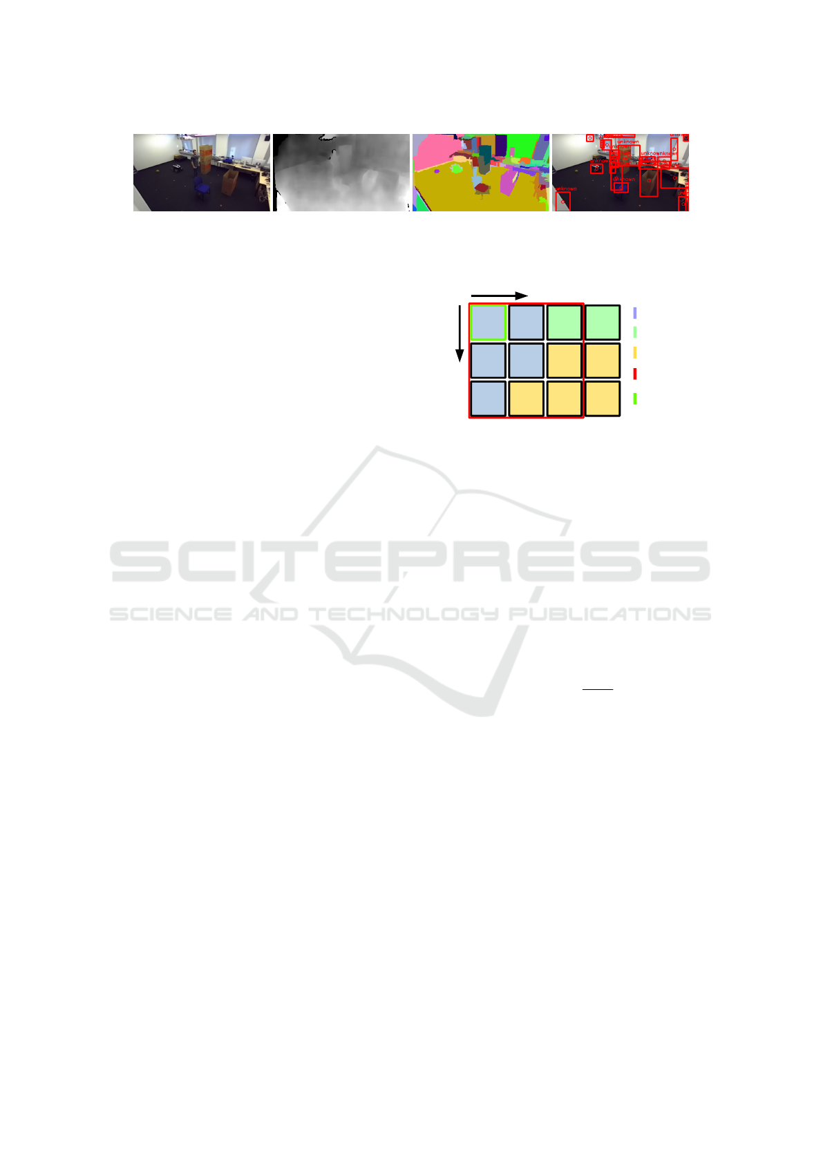
Color image Depth map Segmentation Detection results
Figure 2: Example application of the SO algorithm. The resulting segmentation based on the color image (left) and the depth
map (middle left) is depicted in the middle right with a different color for each segment. The color image with bounding
boxes enclosing detected salient objects is depicted on the right.
The third algorithm is a novel approach inspired by
salient object detection algorithms presented in (Ju
et al., 2014) and (Feng et al., 2016). The key point
of salient object detection algorithms is the compari-
son whether some image region is closer to the ca-
mera than a certain environment around. Those al-
gorithms are mainly designed and evaluated for one
salient object in the picture, so that we developed a
new approach to detect multiple salient objects. Our
approach builds on the image segmentation algorithm
presented in (Felzenszwalb and Huttenlocher, 2004).
The color image as well as the depth map are used in
the segmentation algorithm to divide the depth map
into I segments (cf. Figure 2). After the segmenta-
tion, for each pixel p at the image coordinates (u, v),
its depth d
p
and the segment S
i
it belongs to is known,
with i ∈I. We define the property F(S
i
), that descri-
bes a measure whether the segment S
i
depicts a fore-
ground object or background. First, the pixel in the
top left corner of the image is chosen as a current
pixel p
c
. Based on this current pixel p
c
, a quadra-
tic search window W with an edge length of l pixels
is created. An example search window is depicted in
Figure 3. For each pixel in this window is checked,
if it belongs to the same segment as the current pixel
p
c
. The pixel with the maximal distance to the ca-
mera p
w
that does not belong to the current pixel’s
segment S
i
is selected, since it is the most probable
candidate to represent the background. The depth dif-
ference m(p
c
, p
w
) between the current pixel p
c
and
the selected pixel p
w
is calculated by
m(p
c
, p
w
) = d
p
c
−d
p
w
. (1)
The result of this subtraction is positive if the current
pixel p
c
is closer to the camera, i.e., depicts more pro-
bable a foreground object. It is negative if the selected
pixel p
w
is nearer to the camera, i.e., the current pixel
p
c
belongs more probable to the background. The al-
gorithm processes every pixel p in the image as cur-
rent pixel p
c
. Accordingly, we move the search win-
dow W with a stride of one pixel. If all pixels in-
side the window W belong to the same segment S
i
, no
action is performed. In case a search window W ex-
ceeds the image dimensions, only the available pixels
are included to the window. To decide whether a seg-
(u+1,
v+1)
u
Segment S
1
Segment S
2
Segment S
3
...
...
(u, v) (u+1, v) (u+l, v)
(u, v+1)
(u+l,
v+1)
(u, v+l)
(u+1,
v+l)
(u+l,
v+l)
Window
with l = 3
Current pixel:
p
c
v
...
Figure 3: Example search window of the SO algorithm.
ment S
i
represents a foreground object, we calculate
the property F(S
i
) as follows
F(S
i
) =
∑
p
c
∈S
i
m(p
c
, p
w
) +
∑
p
w
∈S
i
m(p
c
, p
w
). (2)
All results of depth comparisons m(p
c
, p
w
) incorpo-
rating pixels of the segment S
i
, either as actual pixel
p
c
or as pixel with maximal distance inside the search
window p
w
, are summed up. Since small segments
provide fewer comparisons with other segments, we
normalize F(S
i
), so that all segments S are compara-
ble. For normalizing, F(S
i
) is divided by the number
N
i
of comparison results m(p
c
, p
w
) which were added
to F(S
i
) follows
F
N
(S
i
) =
F(S
i
)
N
i
. (3)
The decision whether a segment S
i
depicts a fore-
ground object is defined as
S
i
=
(
foreground object F
N
(S
i
) > F
th
background F
N
(S
i
) ≤ F
th
,
(4)
where F
th
is a threshold value. Bounding boxes are
created enclosing the segments which represent fo-
reground objects. Our NMS algorithm is applied to
these bounding boxes.
The SO algorithm requires a relative long pro-
cessing time of about 0.33 s per image (BS: 0.08 s,
YOLO: 0.13 s). To increase the average measurement
rate, we apply the SO algorithm periodically (3 s),
while the other algorithms evaluate each image. This
periodical evaluation brings no further disadvantages.
Static objects of special interest can be trained for
being detected by YOLO and moving objects are de-
tected by the BS algorithm with a high detection rate.
VISAPP 2019 - 14th International Conference on Computer Vision Theory and Applications
810
5 FUSION OF THE OBJECT
HYPOTHESES
To combine the detection results of the three different
algorithms, we propose a fusion algorithm based on
bounding boxes. We make the reasonable assump-
tion that if the algorithms detect the same object and
output their detection as bounding boxes, these boxes
intersect largely.
The fusion algorithm checks in a first step if the
bounding boxes from any two different algorithms
overlap. In the case that two boxes B
k
and B
l
intersect,
the ratio R between the area of intersection B
k
∩B
l
and
the area of the smaller one of the two boxes is com-
puted by
R =
area(B
k
∩B
l
)
area(B
k
)
if area(B
k
) ≤ area(B
l
)
area(B
k
∩B
l
)
area(B
l
)
if area(B
k
) > area(B
l
).
(5)
This ratio R allows the fusion of boxes also if the
smaller box is completely enclosed by the other box
and of relatively small size compared to it. An ex-
ample is a standing person that turns its head. The
background subtraction detects only the movement of
the head, whereas YOLO and SO detect the whole
person. The fusion would not be performed, if the
common IoU metric is used. However, if the intro-
duced ratio R exceeds a certain threshold value, the
boxes are fused and a new bounding box which enclo-
ses the two original boxes is created. In this process,
also the information of the detected objects are fused,
i.e., the class and the dynamic state. The results for
the different possible pairings are shown in Table 1.
In the case, that the background subtraction detects
an object, this object must be moving, i.e., a dyna-
mic object. If an object is not detected by the back-
ground subtraction, whereas it is detected by another
detection method, this object is considered as static.
In this first step, it is possible, that one box is fused
multiple times with other boxes. The new bounding
boxes created by the fusion process are not used for
further fusion at this stage.
In the second step of the algorithm only the fusion
results of step one and previously not fused boun-
ding boxes are still of interest. The boxes that were
not fused before are passed through as final detection
results. It is possible, that there are multiple object
hypotheses from step one for a single real object (cf.
Figure 4). Consequently, the fusion results from step
one are fused again according to the bounding box
fusion procedure described before. If now two boxes
with different classes from YOLO are to be fused, the
fusion result inherits the class with the higher confi-
dence value provided by YOLO.
As aforementioned, the algorithm is designed to fuse
the results of two object detection algorithms. Ho-
wever, our system works with three approaches. The
fusion of three approaches is performed by first fu-
sing two of them. The fusion results as well as the not
fused detections are then separately fused with the re-
sults of the third algorithm.
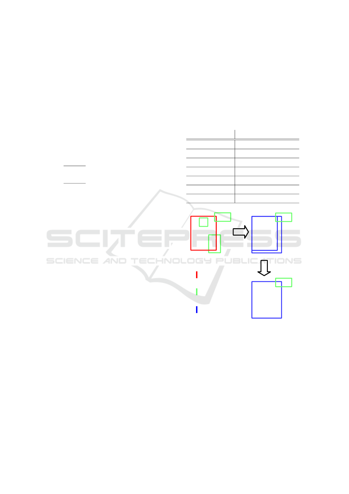
Table 1: Possible information fusion outcomes. The ”+”
shows, that the SO algorithms provides no new information,
but increases the evidence for an object being present.
BS YOLO SO Object hypothesis
X - - dynamic unknown object
- X - static classified object
- - X static unknown object
X X - dynamic classified object
X - X dynamic unknown object +
- X X static classified object +
X X X dynamic classified object +
YOLO
Background subtraction
Fusion
Person
Fusion
Step 1
Dynamic person
Dynamic
object
Dynamic
object
Dynamic
object
Dynamic
object
Dynamic person
Dynamic person
Fusion
Step 2
Dynamic
object
Figure 4: Example for the bounding box fusion algorithm.
A person and three moving objects are detected. In the first
fusion step, two moving objects are fused with the detected
person. The third moving object intersects not sufficient
with another bounding box to be fused. In the second fusion
step, the two boxes describing a dynamic person are fused,
as they largely intersect.
6 OBJECT LOCALIZATION
The localization in the real world of previously in
the image detected objects is performed by using the
point cloud. The point cloud is computed with the two
images of the stereo camera, as described for example
in (Hartley and Zisserman, 2003).
Object Detection, Classification and Localization by Infrastructural Stereo Cameras
811
Since real world objects often have no rectangular
shape and the detection results can be faulty, the boun-
ding boxes partly enclose the background in many ca-
ses. This leads to a difficult localization of the whole
foreground object, as a highly accurate segmentation
would be necessary to distinguish between object and
background. An approach for such high accuracy seg-
mentations based on bounding boxes is presented in
(Lempitsky et al., 2009). The crucial point is, that up
to now the computing power of small platforms (like
the Jetson TX2) is not sufficient to solve this task in an
acceptable time. As a consequence, our localization
approach is based on the 3D position of the pixels in
the center of the bounding box. It is very likely, that
in the center of the box the detected object is present.
Based on this assumption, the 3D coordinates corre-
sponding to the pixels in the center of the bounding
box are extracted from the point cloud. We extract
144 points corresponding to the pixels around the cen-
ter, according to the size of the smallest object to be
detected. The median for the x-, y-, z- position is cal-
culated to deal with possible outliers.
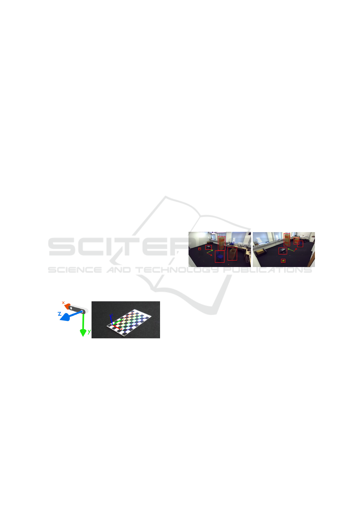
Since the coordinates of the point cloud are ex-
pressed in the camera coordinate system (cf. Fi-
gure 5), we transform the position of the detected ob-
jects in a real-world metric coordinate system. The-
refore the translation and rotation between this two
coordinate systems is necessary. By once placing a
checkerboard in the field of view of the camera, it is
possible to receive the extrinsic parameters. These pa-
rameters describe the transformation between the ca-
mera coordinate system and a real-world metric coor-
dinate system that is based on the checkerboard pat-
tern (Zhang, 2000; Kaehler and Bradski, 2016).
Figure 5: Camera coordinate system (left, https://
www.stereolabs.com) and coordinate system defined by the
checkerboard pattern (right)
After this step, the following information about de-
tected objects are published:
• Time of the measurement
• Class of the detected object, which can also be
unknown, if no class is provided by YOLO
• Dynamic state of the object (static or dynamic)
• 3D-position in the real world metric coordinate
system
7 EVALUATION ON REAL
WORLD DATA
For the evaluation of our proposed system, we use a
test scenario consisting of different objects. These ob-
jects are a chair, a sports ball, a robot and some card-
board boxes, all placed on defined positions. This se-
tup is shown in Figure 6. Additionally to these ob-
jects, a person is walking through the scenario and
rests for several seconds at two specific positions (see
Figure 7). The person enters the measurement setup
at the coordinates (3.5, 1), walks to (0, -1), turns right
and rests at (0, 2) (”Person A”) for a short time. Then
the person moves according to the trajectory to the
position ”Person B” and rests again. From there, the
person moves to (1, -1), turns left and returns to the
starting position.
We evaluate the systems for two different camera
positions, as pictured in Figure 6. For evaluating the
three algorithms and the fusion, we use 150 images
of the measurement setup including the person captu-
red from each camera position. For investigating the
whole system, we saved the detection, classification
and localization results in another measurement run.
y
Cardboard box 1
x
Cardboard box 2
Chair
Sports ball
Robot
Camera position 1
y
x
Cardboard box 2
Chair
Sports ball
Robot
Cardboard box 1
Camera position 2
Figure 6: Images of the measurement setup with the placed
static objects seen from the two camera positions.
In the evaluation setup, the walking person is the only
dynamic object, hence the only detectable object for
the BS. The training dataset of YOLO includes the
classes chair, sports ball and person, so these three
objects in the test setup are to be detected and classi-
fied by the CNN. The person can be detected by the
CNN when moving, but also when resting. The algo-
rithm for detecting salient objects is able to detect all
the objects in the our setup, including the robot and
the cardboard boxes.
To evaluate the algorithms and the fusion algo-
rithm, we use the IoU metric for evaluating boun-
ding boxes described in (Everingham et al., 2010).
First, for all images the true bounding boxes and clas-
ses were annotated by hand. Afterwards, a program
checks if a bounding box from an algorithm or the
fusion has an IoU with a true bounding box = 0.5.
If so, the box is considered as correct detection. In
the case that multiple boxes have an IoU = 0.5 with
the same true box, only the box with the greatest IoU
is considered as correct. The other ones are conside-
VISAPP 2019 - 14th International Conference on Computer Vision Theory and Applications
812

red as false detections, similar to bounding boxes that
have an IoU < 0.5 or no intersection with a true box.
Missed detections are counted in case that an object is
not detected. We define the detection ratio as correct
detections over possible detections. If a detection is
correct, it is checked if also the classification is right.
In Table 2 the evaluation results of background
subtraction, YOLO and the their fusion only for de-
tecting and classifying the person (walking and res-
ting) are presented. With the camera at position one,
the background subtraction works quite well at any
time, as the moving person is always detected. YOLO
detects the person walking only occasional and never
the person resting. If YOLO detects the person, the
classification is always correct. The number of de-
tections made by YOLO is influenced by the minimal
confidence threshold for outputs (see also (Redmon
et al., 2016)), which we selected 0.5. By selecting
this value, we have a balance between too many false
detections and too few correct detections. The fact
that YOLO does not detect the resting person leads to
the effect that with the fusion the detection rate is not
increased. The absolute number of correct classifica-
tions increases from 21 to 27 due to the fusion. By
the fusion, the bounding box size of too small boxes
from YOLO is corrected based on the boxes from the
background subtraction. The wrong detections of the
background subtraction and subsequent of the fusion
are caused by shadows, which are generated by the
person. The false detections from YOLO are those
too small bounding boxes, that are eliminated by the
fusion algorithm. At camera position two, the de-
tection rate increases by using the fusion as YOLO
can also detect the person resting at certain instances
(cf. Figure 7). Similar to camera position one, the
effect concerning increased absolute correct classifi-
cations is visible. The number of false detections is
high compared to camera at position one. This high
number is on the one hand caused by the shadows,
as already described. On the other hand, the walking
person is relatively far away from the camera (about 8
meters) at its starting position and endpoint. At these
distances the background subtraction algorithm crea-
tes too big bounding boxes. This results in a false and
a missed detection. YOLO outputs 17 false detecti-
ons, as for the person resting at position B two boun-
ding boxes are created (see Figure 7). Accordingly,
one of the two bounding boxes is considered as false.
Summed up, this first evaluation proofs that by ap-
plying our fusion approach, the detection of the per-
son improves compared to using only the CNN or the
background subtraction. Furthermore, the system can
classify the person additionally in some images, what
can be used in a future tracking algorithm to clas-
Table 2: Evaluation of the BS algorithm, YOLO and their
fusion for the person.
Camera Position 1
Method BS YOLO Fusion
Possible detections 118 118 118
Correct detections 95 21 95
Detection ratio 0.81 0.18 0.81
Correct classifictations - 21 27
Missed dections 23 97 23
False detections 9 6 9
Camera Position 2
Method BS YOLO Fusion
Possible detections 139 139 139
Correct detections 96 53 114
Detection ratio 0.69 0.38 0.82
Correct classifictations - 53 61
Missed dections 43 86 25
False detections 31 17 43
Table 3: Evaluation of the SO algorithm and the fusion of
all three algorithms for all objects in the measurement setup.
Camera Position 1 Position 2
Method SO Fusion SO Fusion
Possible detections 832 832 860 860
Correct detections 303 397 352 454
Detection ratio 0.36 0.48 0.41 0.53
Missed dections 529 435 508 406
False detections 495 383 412 342
sify objects, also when no detection is provided by
the CNN.
In Table 3 the results of the SO algorithm and the
fusion of all three algorithms are presented. For this
evaluation, the SO algorithm was not applied periodi-
cally but to every image. The number of total possible
detections increases, as now all objects in the measu-
rement setup are detectable for our system. Since the
SO algorithm detects objects in the whole image (see
Figure 2), we adopted the evaluation metric for this
algorithm, so that only the placed test objects are in-
cluded in the evaluation. Only bounding boxes from
SO that have an IoU with a true box > 0.1 are consi-
dered. By using this threshold, only bounding boxes
that show a sufficient cue for being a detection (also
false) of the placed object are evaluated. The de-
tection ratio of SO is only 0.36. Moreover, there is
a great number of false detections. These numbers
arise from too small bounding boxes for detected ob-
jects output by the SO algorithm. Consequently, the
IoU with a true box is < 0.5 and thus a false detection.
Those false box dimensions are caused by the seg-
mentation, as the segments often do not fit to the real
object shapes. Furthermore, objects that were relati-
vely far away from the camera were not detected well,
as also obvious in Figure 7. The reason therefore is,
Object Detection, Classification and Localization by Infrastructural Stereo Cameras
813
that with increasing distance the quality of the depth
estimation declines. Comparing the results of the SO
algorithm with those of the fusion, the improvements
by the fusion are clearly visible.
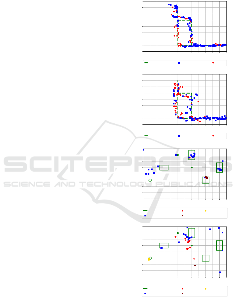
In Figure 7, the detection, classification and lo-
calization results from both camera positions are de-
picted. It is to note, that in this figure all detections
of the system are presented, also detections that were
considered as false in the evaluation before. The re-
sults are depicted in the x-y-plane of the coordinate
system defined by the checkerboard pattern. For cla-
rity we have split the results showing detected dyna-
mic objects (top) and detected static objects (bottom).
The top maps of Figure 7 depict the detected dy-
namic objects, in the evaluation scenario the walking
person. Additionally, the ground truth of the person’s
trajectory is shown. The moving person is detected
and localized on the whole trajectory. However, there
are many detections of the person as unknown dyn-
amic object (BS) and some as dynamic person (fu-
sion). These results are consistent with the evaluation
before. The errors in the localization are explainable
by:
• Faulty 3D coordinates of the point cloud
• Errors in the transformation between the coordi-
nate systems
• The detected object is not present in the center
of the bounding box, so that a point in the back-
ground is localized.
Since we achieved a mean reprojection error by aver-
aging the reprojection errors of all checkerboard cor-
ners of 0.14 pixels for camera position one and 0.25
pixels for camera position two, we infer that the trans-
formation between the coordinate systems has only a
small impact on the localization error. Moreover, the
real person has dimensions larger than the line used
as ground truth. A small deviation of the person’s lo-
calization from this line is accordingly not surprising.
Averaging the minimal euclidean distance to the true
trajectory for all measurements, we achieve a mean
error of 0.1 meters for the camera at position one and
of 0.13 meters for the camera at position two.
Considering the static objects (Figure 7 bottom),
the system only detects those objects that are relati-
vely near to the camera. Furthermore, the number of
detections of cardboard boxes is small compared to
number of chair detections. The SO algorithm detects
the cardboard boxes only periodically (3 s), whereas
YOLO is able to detect the chair approximately in
every obtained measurement. This effect is also vi-
sible at camera position two. The localization error of
the detections of the chair, sports ball and robot is very
small, and different measurements are localized close
−2.5 −2.0 −1.5 −1.0 −0.5 0.0 0.5 1.0 1.5 2.0 2.5 3.0 3.5
x in m
−1.5
−1.0
−0.5
0.0
0.5
1.0
1.5
2.0
2.5
y in m
True trajectory Unknown object Person
Camera position 1: Dynamic objects
−2.5 −2.0 −1.5 −1.0 −0.5 0.0 0.5 1.0 1.5 2.0 2.5 3.0 3.5
x in m
−1.5
−1.0
−0.5
0.0
0.5
1.0
1.5
2.0
2.5
y in m
True trajectory Unknown object Person
Camera position 2: Dynamic objects
−2.5 −2.0 −1.5 −1.0 −0.5 0.0 0.5 1.0 1.5 2.0 2.5 3.0 3.5
x in m
−1.5
−1.0
−0.5
0.0
0.5
1.0
1.5
2.0
2.5
y in m
Chair
Cardboard box 1
Cardboard box 2
Sports ball
Robot
Person A
Person B
Ground truth
Unknown object
Person
Chair
Sports ball
Camera position 1: Static objects
−2.5 −2.0 −1.5 −1.0 −0.5 0.0 0.5 1.0 1.5 2.0 2.5 3.0 3.5
x in m
−1.5
−1.0
−0.5
0.0
0.5
1.0
1.5
2.0
2.5
y in m
Chair
Cardboard box 1
Cardboard box 2
Sports ball
Robot
Person A
Person B
Ground truth
Unknown object
Person
Chair
Sports ball
Camera position 2: Static objects
Figure 7: Localization results obtained with our system and
ground truth depicted in the x-y-plane of the checkerboard
coordinate system.
VISAPP 2019 - 14th International Conference on Computer Vision Theory and Applications
814

together. The bounding boxes for these objects were
always chosen very similarly, which leads to this clo-
sely spaced localization pattern. In contrast, the boun-
ding boxes for the cardboard boxes often had different
sizes. This results in the wider spread of the localiza-
tions. In the bottom maps of Figure 7 also some false
measurements are present. These measurements are
mostly caused by the SO algorithm, due to false lo-
calizations of other objects in the room. We reach an
average detection rate of approximately 7.5 Hz, which
is sufficient for a real time application.
8 CONCLUSION AND FUTURE
WORK
In this contribution, we presented an infrastructural
stereo camera system for real-time object detection,
classification and localization. By using three diffe-
rent complementary approaches for object detection,
the system has the ability to detect almost every object
in its field of view. With our proposed fusion algo-
rithm for bounding boxes we improved the detection
and classification results, as presented in the evalua-
tion. The localization approach based on the stereo
camera shows satisfying results. However, further re-
search concerning the localization of the whole ob-
ject, not only a point, is of high interest. In the fu-
ture, we plan to improve the detections by training
the CNN with images captured by the system. Furt-
hermore, improvements concerning the algorithm for
salient object detection are planned. Additionally, we
will expand the system by a tracking algorithm.
REFERENCES
Einsiedler, J., Becker, D., and Radusch, I. (2014). Ex-
ternal visual positioning system for enclosed car-
parks. In Positioning, Navigation and Communication
(WPNC), 2014 11th Workshop on, pages 1–6. IEEE.
Einsiedler, J., Radusch, I., and Wolter, K. (2017). Vehicle
indoor positioning: A survey. In Positioning, Naviga-
tion and Communications (WPNC), 2017 14th Works-
hop on, pages 1–6. IEEE.
Everingham, M., Van Gool, L., Williams, C. K., Winn, J.,
and Zisserman, A. (2010). The pascal visual object
classes (voc) challenge. International journal of com-
puter vision, 88(2):303–338.
Felzenszwalb, P. F. and Huttenlocher, D. P. (2004). Effi-
cient graph-based image segmentation. International
journal of computer vision, 59(2):167–181.
Feng, D., Barnes, N., You, S., and McCarthy, C. (2016).
Local background enclosure for rgb-d salient object
detection. In Proceedings of the IEEE Conference
on Computer Vision and Pattern Recognition, pages
2343–2350.
Hartley, R. and Zisserman, A. (2003). Multiple view geome-
try in computer vision. Cambridge university press.
Ibisch, A., Houben, S., Michael, M., Kesten, R., and
Schuller, F. (2015). Arbitrary object localization and
tracking via multiple-camera surveillance system em-
bedded in a parking garage. In Video Surveillance
and Transportation Imaging Applications 2015, vo-
lume 9407, page 94070G. International Society for
Optics and Photonics.
Ibisch, A., Houben, S., Schlipsing, M., Kesten, R., Reim-
che, P., Schuller, F., and Altinger, H. (2014). Towards
highly automated driving in a parking garage: General
object localization and tracking using an environment-
embedded camera system. In Intelligent Vehicles
Symposium Proceedings, 2014 IEEE, pages 426–431.
IEEE.
Ju, R., Ge, L., Geng, W., Ren, T., and Wu, G. (2014). Depth
saliency based on anisotropic center-surround diffe-
rence. In Image Processing (ICIP), 2014 IEEE In-
ternational Conference on, pages 1115–1119. IEEE.
Kaehler, A. and Bradski, G. (2016). Learning OpenCV
3: computer vision in C++ with the OpenCV library.
O’Reilly Media, Inc.
Kumar, A. K. T. R., Sch
¨
aufele, B., Becker, D., Sawade, O.,
and Radusch, I. (2016). Indoor localization of vehicles
using deep learning. In World of Wireless, Mobile and
Multimedia Networks (WoWMoM), 2016 IEEE 17th
International Symposium on A, pages 1–6. IEEE.
Lempitsky, V. S., Kohli, P., Rother, C., and Sharp, T. (2009).
Image segmentation with a bounding box prior. In
ICCV, pages 277–284. Citeseer.
Redmon, J., Divvala, S., Girshick, R., and Farhadi, A.
(2016). You only look once: Unified, real-time object
detection. In Proceedings of the IEEE conference on
computer vision and pattern recognition, pages 779–
788.
Redmon, J. and Farhadi, A. (2017). Yolo9000: better, faster,
stronger. arXiv preprint.
Zhang, Z. (2000). A flexible new technique for camera ca-
libration. IEEE Transactions on pattern analysis and
machine intelligence, 22(11):1330–1334.
Zitnick, C. L. and Doll
´
ar, P. (2014). Edge boxes: Locating
object proposals from edges. In European conference
on computer vision, pages 391–405. Springer.
Zivkovic, Z. (2004). Improved adaptive gaussian mixture
model for background subtraction. In Pattern Recog-
nition, 2004. ICPR 2004. Proceedings of the 17th In-
ternational Conference on, volume 2, pages 28–31.
IEEE.
Zivkovic, Z. and Van Der Heijden, F. (2006). Efficient adap-
tive density estimation per image pixel for the task of
background subtraction. Pattern recognition letters,
27(7):773–780.
Object Detection, Classification and Localization by Infrastructural Stereo Cameras
815
