
B-SLAM-SIM: A Novel Approach to Evaluate the Fusion of Visual
SLAM and GPS by Example of Direct Sparse Odometry and Blender
Adam Kalisz
1
, Florian Particke
1
, Dominik Penk
2
, Markus Hiller
1
and J
¨
orn Thielecke
1
1
Department of Electrical, Electronic and Communication Engineering, Information Technology (LIKE),
Friedrich-Alexander-Universit
¨
at Erlangen-N
¨
urnberg, Am Wolfsmantel 33, Erlangen, Germany
2
Department of Computer Science, Computer Graphics Lab (LGDV),
Friedrich-Alexander-Universit
¨
at Erlangen-N
¨
urnberg, Cauerstraße 11, Erlangen, Germany
Keywords:
Fusion, Global Positioning System, Visual Simultaneous Localization and Mapping, GPS, SLAM, Simula-
tion, Blender.
Abstract:
In order to account for sensor deficiancies, usually a multi-sensor approach is used where various sensors
complement each other. However, synchronization of highly accurate Global Positioning System (GPS) and
video measurements requires specialized hardware which is not straightforward to set up. This paper proposes
a full simulation environment for data generation and evaluation of Visual Simultaneous Localization and
Mapping (Visual SLAM) and GPS based on free and open software. Specifically, image data is created by
rendering a virtual environment where camera effects such as Motion Blur and Rolling Shutter can be added.
Consequently, a ground truth camera trajectory is available and can be distorted via additive Gaussian noise
to understand all parameters involved in the use of fusion algorithms such as the Kalman Filter. The proposed
evaluation framework will be published as open source online at https://master.kalisz.co for free use by the
research community.
1 INTRODUCTION
Artificial Intelligence and Machine Learning are the
main building blocks for many of the recent advances
in robotics. Self driving cars usually employ an
expensive set of sensors (Sebastian Thrun, Udacity,
Inc., 2018) in order to understand their environment.
3D laser scanners are a popular choice for this task.
Although such devices can provide highly accurate
measurements, they are large, sensitive, cumbersome
to transport and need quite some time to create a full
scan of the environment. This makes them a great
choice to get a metric, real world scale 3D point cloud
but hard to operate on moving platforms or vehicles.
The area of camera-based localization and mapping is
a well-studied field and an impressive amount of work
has been done on creating open source algorithms
which can easily accomplish this goal. Yet, there are
still challenging situations where the addition of a
second sensor may be a good option. Some cameras
can provide a global reference to where the camera is
currently located (geotagging) in video mode, such
as recent versions of the GoPro Hero action camera
series
1
. It is therefore highly motivating to investigate
such cost-effective devices that allow for localization
and mapping at the same time. In order to compare
fusion of VSLAM and GPS with a ground truth refe-
rence, this research is based on a controllable simu-
lation environment where an artist can create challen-
ging scenarios that are not trivial to find in the real
world on the one hand and investigate the influence
of specific sensor characteristics and deficiencies on
the other hand.
2 RELATED WORK
After many years of research in this field, there is al-
ready a plethora of sophisticated software packages
available which are able to estimate highly accurate
camera poses and 3D point clouds from a set of ima-
ges.
Popular commercial software includes Photoscan
(Agisoft LLC, 2014), Reality Capture (Capturing Re-
ality, 2018), built by creators of CMPMVS (Jancosek,
1
https://gopro.com/compare
816
Kalisz, A., Particke, F., Penk, D., Hiller, M. and Thielecke, J.
B-SLAM-SIM: A Novel Approach to Evaluate the Fusion of Visual SLAM and GPS by Example of Direct Sparse Odometry and Blender.
DOI: 10.5220/0007375308160823
In Proceedings of the 14th International Joint Conference on Computer Vision, Imaging and Computer Graphics Theory and Applications (VISIGRAPP 2019), pages 816-823
ISBN: 978-989-758-354-4
Copyright
c
2019 by SCITEPRESS – Science and Technology Publications, Lda. All rights reserved

Michal and Pajdla, Tomas, 2012) and Syntheyes (An-
dersson Technologies LLC, 2018).
Although the basic ideas might be similar in all
algorithms, they may be distinguished by a few pro-
perties. The most obvious difference between to-
days state-of-the-art approaches may be considered
the idea of indirect (feature-based) against direct met-
hods (Krombach et al., 2016). The former transforms
image data into a feature space representation first and
then proceeds with the camera pose and 3D structure
information extraction by minimizing a geometric er-
ror. On the contrary, latter methods directly use image
data to perform SLAM by minimizing a photometric
error, thus those are called direct approaches. Re-
cently, a third approach gains increasing popularity:
Machine-Learning methods (Mohanty et al., 2016).
Although these could be a game-changer in this re-
search field, up to the authors knowledge all of them
either require large datasets specific to a certain scena-
rio used for the mandatory training phase (Vijayana-
rasimhan et al., 2017) or are only able to reconstruct
isolated objects in a scene (Choy et al., 2016). Still,
these approaches look very promising (Eslami et al.,
2018) and are expected to soon provide mature alter-
natives to traditional feature extraction and tracking
techniques.
Open source software that uses indirect methods
includes Blender’s (Blender Foundation, 2018) inte-
grated multi view library LibMV (Blender Contribu-
tors, 2018), the state-of-the-art of feature-based met-
hods ORB-SLAM2 (Mur-Artal and Tard
´
os, 2017),
Visual SfM (Changchang Wu, 2018), COLMAP
(Sch
¨
onberger and Frahm, 2016) and a recent frame-
work called AliceVision, which is funded by the Eu-
ropean Unions Horizon 2020 research and innovation
programme (Czech Technical University (CTU) et.
al., 2018).
Examples of state-of-the-art open source software
that uses direct methods is Direct Sparse Odometry
(DSO) (Engel et al., 2017), which is used in this work
and its predecessor Large Scale Direct SLAM (LSD-
SLAM) (Engel et al., 2014). Additionally, hybrid im-
plementations of indirect and direct methods exist, for
example Fast Semi-Direct Monocular Visual Odome-
try (SVO) (Forster et al., 2014).
The fusion of sensors providing a navigation solu-
tion and camera-based vision is an active field of rese-
arch. Related work focused on fusing inertial measu-
rements with visual measurements from a monocular
camera (Mourikis and Roumeliotis, 2007), investiga-
ted the accurate estimation of a relative bearing be-
tween two vehicles by fusing vision algorithms and
GPS (Amirloo Abolfathi, 2015) or integrated a cus-
tom satellite navigation receiver tightly with a stereo
camera (Aumayer, 2016).
To the authors knowledge, however, there is no re-
search which investigates the fusion of direct methods
and GPS. During the evaluation of our work, the aut-
hors of Direct Sparse Odometry (DSO) published a
paper on fusing inertial sensors and Stereo-DSO, cal-
ling it Direct Visual-Inertial Odometry (Usenko et al.,
2016). However, fusion with GPS still remains an
open question. Therefore, this paper aims to propose
a flexible pipeline for the research community to eva-
luate the fusion of GPS and DSO. This includes ge-
neration of usually not available ground truth data and
the flexibility to investigate various fusion approaches
more closely. Our framework targets the influence
of sensor deficiencies in special environments which
are normally hard to record in an appropriate manner
when using real sensors.
3 DATASET
From all the created virtual environments, four of
them are included here where qualitative evaluation
was performed. Figure 1 depicts their individual tra-
jectories from the top view.
(a) Scenario 1: Scene-
City straight linear con-
stant velocity
(b) Scenario 2: Venice da-
taset with loop closure
(c) Scenario 3: Damaged
Downtown dataset with
loop closure
(d) Scenario 4: SceneCity
dataset with loop closure
Figure 1: Four scenarios have been selected for evaluation.
A final render of the scenario visualized in Figure 1(a)
is presented in Figure 2(a). Figure 2 includes a few
challenging types of sensor characteristics in Visual
SLAM applications which can all be simulated using
our proposed system. Camera effects such as Mo-
tion Blur, Rolling Shutter and Automatic Gain Con-
trol (i.e. varying image brightness) can be added. Ho-
wever, the evaluation part of this paper investigates
ideal real-time renderings not including any of such
errors as we noticed that the DSO algorithm can be
quite sensitive to them.
B-SLAM-SIM: A Novel Approach to Evaluate the Fusion of Visual SLAM and GPS by Example of Direct Sparse Odometry and Blender
817
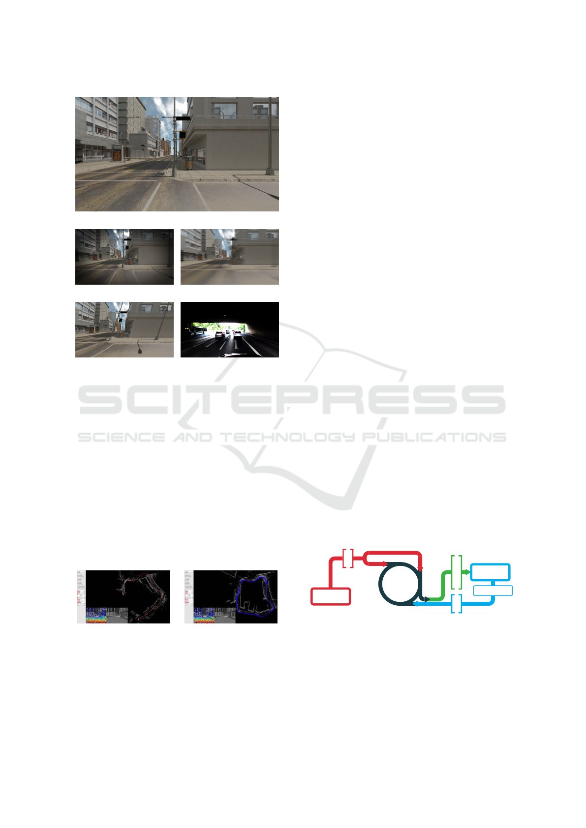
(a) Original (ideal) image
(b) Lens vignetting (c) Motion blur
(d) Rolling shutter (e) Contre-jour shot
Figure 2: Some of the challenges for Visual SLAM algo-
rithms.
The trajectories reconstructed via DSO were usu-
ally reasonably good and have been passed on to the
processing stage where fusion with GPS was perfor-
med. However, we noticed that camera rotations may
cause a strong drift. This happened in our experi-
ments more likely in open areas (i.e. wide streets in
Scenario 3) as opposed to narrow passageways (such
as the camera path through Venice in Scenario 2). Per-
forming two tests where the camera was both rotating
and moving on the one hand (compare Figure 3(a))
and only moving while keeping rotation locked on the
other hand (compare Figure 3(b)) can clearly show the
difference. Figure 3 summarizes the virtual scene and
their reconstructions in the DSO.
(a) DSO result: Dama-
ged Downtown (rotating
camera)
(b) DSO result: Damaged
Downtown (no rotating ca-
mera)
Figure 3: Virtual environment of a damaged downtown do-
wnloaded from the website Open3DModel.
4 FUSION
The diversity of available sensors used by robots to
sense their environments render multisensor data fu-
sion a challenging task, especially when the measu-
rements of those sensors need to be integrated into
a final navigation solution (Mueller and Massaron,
2018).
Multiple sensor readings could be combined in
different ways (Khaleghi et al., 2013). Generally, the
right approach needs to consider issues like imper-
fection, modality, dimensionality and correlation of
data.
A very elegant and popular way from the class
of stochastic fusion methods, that is applicable un-
der Gaussian assumptions, is to use a Kalman filter
(Marchthaler and Dingler, 2017).
This chapter provides an overview of the main
sensor data fusion concept in this work. Complex in-
tegration architectures such as loose, tight and ultra-
tight coupling are often employed when sensors are
fused. Thus, full access to these sensor sources is re-
quired to route back the prediction from a filter step
to initialize new calculations. The result is a highly
customized system that only works for one type of
sensor configuration. In the course of this work, we
chose to show capabilities of the proposed framework
by evaluating the fusion of DSO and GPS. It is pos-
sible, however, to exchange Visual SLAM algorithms
freely, as this work examines an uncoupled approach
where Visual SLAM and GPS settings can be modi-
fied individually in order to investigate their effects.
4.1 Overview
This research is based on the following concept il-
lustrated in Figure 4 which should give the reader an
overview of the main components of this work:
Linear
Kalman
Filter
Update (GPS)
GPS
x
y
z
Init (GPS)
Predict
Update (DSO)
GPS
DSO
Dierentiation
DSO
vx
vy
vz
Filtered
x
y
z
vx
vy
vz
Figure 4: Main filter cycle.
A Kalman filter basically consists of a prediction
and an update step. The prediction step takes the cur-
rent state of the system and projects the next state
ahead by using the underlying motion model. Ad-
ditionally, it determines the state covariance matrix
and adds uncertainty. The update step will use an
VISAPP 2019 - 14th International Conference on Computer Vision Theory and Applications
818

available measurement to correct the prediction ba-
sed on the sensor model. However, since this rese-
arch fuses two sensor sources, namely GPS and Vi-
sual SLAM, the update step is executed either once
or twice, depending on what sensor measurement is
available. The Kalman filter algorithm continues re-
cursively by repeating those steps over and over again
until all frames are processed or the program ends.
Figure 4 depicts this cycle graphically
2
. Firstly, the
Kalman filter needs to be initialized. This is done by
taking the 3D position provided by the GPS sensor
to reduce the delay until the Kalman filter converges
to an optimal solution. The Visual SLAM algorithm
provides position measurements as well. However,
due to unknown transformations of the involved coor-
dinate systems, the use of position updates will lead
to wrong results. Therefore, the velocity is calculated
via differentiation from the position measurements,
which is then used for the update step in the Kalman
filter implementation.
At every executed cycle, the Kalman filter provi-
des an estimate of the current state vector, which can
then be used to integrate with the sensors through a
feedback route using a coupled architecture.
The fusion of GPS measurements with Visual
SLAM is prepared using three steps. Firstly, synthe-
tic environments where a virtual camera was moved
are generated. This is considered the ground truth re-
ference. Secondly, in order to simulate noisy GPS
readings, synthetic noise is added to the ground truth
using a Gaussian distribution. Thirdly, the image se-
quence used in the DSO is generated by means of
rendering the viewpoint of the moving camera in-
cluding any sensor errors (Ehlenbr
¨
oker et al., 2016)
which is then processed by the Visual SLAM algo-
rithm. Finally, the fusion of both Visual SLAM and
GPS measurements is performed using a Kalman fil-
ter. The remainder of this chapter is dedicated on defi-
ning the fusion concept evaluated using our proposed
simulation-based framework.
4.2 Coordinate Systems
In order to export properly oriented camera poses
from Blender to the DSO algorithm and vice versa,
it was necessary to align their coordinate systems.
While both are right-handed, they use different up
vectors for the orientation of the camera. Blender uses
2
Please note, that the colors should not mislead the re-
ader in the sense that the prediction and update steps may
be disconnected from the main loop. The reason for co-
loring the components of the cycle like this is to keep the
same style throughout this document, especially later in the
evaluation plots.
the positive y-axis and DSO uses a negative y-axis as
the up vector. However, the urban scenarios in Blen-
der were created in the x-y plane, thus this rotation
needs to be taken into account as well.
4.3 Linear Kalman Filter
The Kalman filter is a state estimator. Therefore, the
physical representation of the camera pose needs to
be modeled by first defining a state. The state vector
used in this work consists of the position in x, y, z and
the respective velocities in v
x
, v
y
, v
z
x
Blender
=
x v
x
y v
y
z v
z
T
. (1)
The a-priori state
ˆ
x
−
k
for timestep k is calculated
using a constant velocity motion model (Zhai et al.,
2014) and the process noise covariance matrix Q
k−1
can be determined by solving the underlying differen-
tial equations of the physically based constant velo-
city motion model (Particke et al., 2017) for the two-
dimensional case. For this work a three dimensional
extension of the proposed matrix is needed as the state
vector supports vertical movements as well and the
camera trajectory does not necessarily only consist of
planar motion. Based on the proposed power spectral
density for velocity σ
v
of the physical motion we de-
fine the following temporary values
d1
t
= σ
v
∆t, (2)
d2
t
= σ
v
∆t
2
2
, (3)
and
d3
t
= σ
v
∆t
3
3
+ d1
t
, (4)
to compose the process noise as
Q
k−1
=
d3
t
d2
t
0 0 0 0
d2
t
d1
t
0 0 0 0
0 0 d3
t
d2
t
0 0
0 0 d2
t
d1
t
0 0
0 0 0 0 d3
t
d2
t
0 0 0 0 d2
t
d1
t
k−1
. (5)
The error model for the simulated GPS in Blen-
der can be trivially provided, since this is a setting
that can be comfortably set during the creation of the
simulation data. It is much more difficult to deter-
mine the error of the DSO and real sensors. However,
this work proposes a simulation environment with a
user friendly and quick way to investigate specific fu-
sion approaches and how they react on different error
models as it offers a full pipeline from importing test
data to generating the final plots visualizing positions,
velocities and errors of the sensor data fusion with just
a few mouse clicks.
B-SLAM-SIM: A Novel Approach to Evaluate the Fusion of Visual SLAM and GPS by Example of Direct Sparse Odometry and Blender
819

5 RESULTS
In order to gain more insight about specific limitati-
ons of the investigated fusion algorithm and to show
capabilities of the proposed simulation-based frame-
work, the following test cases on each scenario from
Figure 1 have been explored:
1. Only position updates from GPS
2. Fusion of position from GPS and DSO
3. Fusion of position from GPS and DSO, where
DSO was aligned with ground truth in Blender
4. Fusion of position from GPS and velocity from
DSO
5. Variation of GPS frequency from one per frame
(T = 1/25s) to one per two seconds (T =
50/25s = 2 s), assuming the video frame rate is
set to 25 frames per second.
By default, the initial position in the Kalman filter
is set to the zero vector
0m 0 m 0 m
T
. The stan-
dard deviations in the measurement noise covariance
matrices for GPS and DSO are set to σ
GPS
= 1.0m
and σ
DSO
= 5.0m, respectively. The frequency of
GPS updates is f
GPS
= 25 Hz. The standard devia-
tions of position and velocity used in the state error
covariance matrix are σ
x0
= 0.02 m and σ
v0
= 0.4 m,
respectively. Finally, the power spectral density used
in the process noise covariance matrix is set to σ
v
=
0.2m
2
/s
2
. The noisy GPS was simulated with a stan-
dard deviation of σ
x
= σ
y
= 1.0m.
5.1 Scenario 1: SceneCity Constant
Linear Velocity
Figure 5: Scenario 1: Only GPS position updates, every
50th frame
Top: 2D trajectory visualizing x and y coordinates
Bottom: RMSE position error of prediction in x, y and z.
A basic test case where merely GPS position me-
asurement updates are available every 50th frame is
illustrated in Figure 5 showing the standard visuali-
zation plots provided by our simulation framework.
DSO position measurements, that have been manually
aligned with the ground truth in Blender beforehand,
are ignored in this case. At every frame a predicted
state is calculated using the constant velocity motion
model. Therefore, the filtered result contains discon-
tinuities in the position estimate. However, as GPS
only updates x and y coordinates, there is no change
in z noticeable.
Figure 6: Scenario 1: GPS and DSO position updates, every
50th frame, initialized
Top: 2D trajectory visualizing x and y coordinates
Bottom: RMSE position error of prediction in x, y and z.
The fusion of raw GPS and DSO position mea-
surements with an initialization of the Kalman filter
using the ground truth is depicted in Figure 6. Due to
the more frequent DSO updates the prediction moves
very quickly towards the DSO measurements increa-
sing the error in the estimate over time. Our simu-
lation framework helps to identify the presence of a
non-zero-mean Gaussian offset in the generated figu-
res of this fusion approach. Hence, raw position mea-
surements are not well suited in this case and thus it is
necessary to investigate an alternative fusion method.
Consequently, the fusion of raw GPS position and
raw DSO velocity measurement updates is depicted
in Figure 7. GPS measurements are taken every 50th
frame causing the prediction to converge slower to-
wards the ground truth. However, DSO velocity up-
dates still have an influence on the prediction slowing
it down along the y axis. Therefore, even the effects
of drift or scale variation can be discovered using our
simulation framework.
To summarize, this scenario of a linear camera
movement is well suited for the used sensor data fu-
sion approach. Note however, since the DSO is sca-
led down when compared to the ground truth, velocity
VISAPP 2019 - 14th International Conference on Computer Vision Theory and Applications
820

Figure 7: Scenario 1: GPS position and DSO velocity up-
dates, every 50th frame
Top: 2D trajectory visualizing x and y coordinates
Bottom: RMSE position error of prediction in x, y and z.
updates may slow down the prediction. Consequently,
if the DSO has a bigger scale, the prediction may es-
timate a location ahead of the current one.
5.2 Scenario 2: Venice Loop
Figure 8: Scenario 2: GPS position and DSO velocity up-
dates, every 50th frame
Top: 2D trajectory visualizing x and y coordinates
Bottom: RMSE position error of prediction in x, y and z.
The fusion of raw GPS and raw DSO velocity
measurement updates for scenario 2 is presented in
Figure 8. GPS readings are provided at every 50th
frame. No initialization is provided to the Kalman fil-
ter. Although this solution tends to converge for x and
y, the frequency of GPS measurement updates is too
slow for this scenario causing errors in the estimate
most notably when the camera turns.
To summarize, in this scenario consisting of a
loop the linear Kalman filter will likely overshoot in
parts where the camera turns. This particular scena-
rio consists of very narrow curves and long distances
with a mostly linear and straight camera movement.
Although the camera did not move very fast around
the corners, it can be seen that the introduced non-
linearities had a large influence on the final result.
5.3 Scenario 3: Damaged Downtown
Loop
Figure 9: Scenario 3: GPS and DSO (aligned) position up-
dates, every 50th frame, initialized
Top: 2D trajectory visualizing x and y coordinates
Bottom: RMSE position error of prediction in x, y and z.
The fusion of raw GPS and aligned DSO position
measurement updates for scenario 3 is illustrated in
Figure 9. Unfortunately, a proper manual alignment
of the DSO trajectory with the ground truth was im-
possible. At every main corner where the camera is
turning, the drift in the DSO trajectory increased dra-
matically causing it to not close the loop anymore.
Consequently, not using any GPS measurements in
this situation would never close the loop again. There-
fore, GPS readings are provided at every 50th frame.
As it is impossible to align the DSO trajectory cor-
rectly with the ground truth, this test case will not pre-
dict the correct values at all but rather cause them to
drift away from the ground truth as was already noti-
ced in Figure 6.
The fusion of raw GPS position and DSO velocity
measurement updates is presented in Figure 10. GPS
readings are provided at every 50th frame. The slow
update rate of GPS causes the prediction to cut cor-
ners in this particular scenario which is not desirable
for urban environments.
To summarize, this scenario lead to the problem in
the DSO, that it did not correctly close the loop. Com-
pared to the GPS measurements, the effects of drift
were significant. The evaluations show that a fusion
with GPS is capable of solving this issue and thus clo-
sing the loop, even when the Visual SLAM algorithm
does not support it.
B-SLAM-SIM: A Novel Approach to Evaluate the Fusion of Visual SLAM and GPS by Example of Direct Sparse Odometry and Blender
821
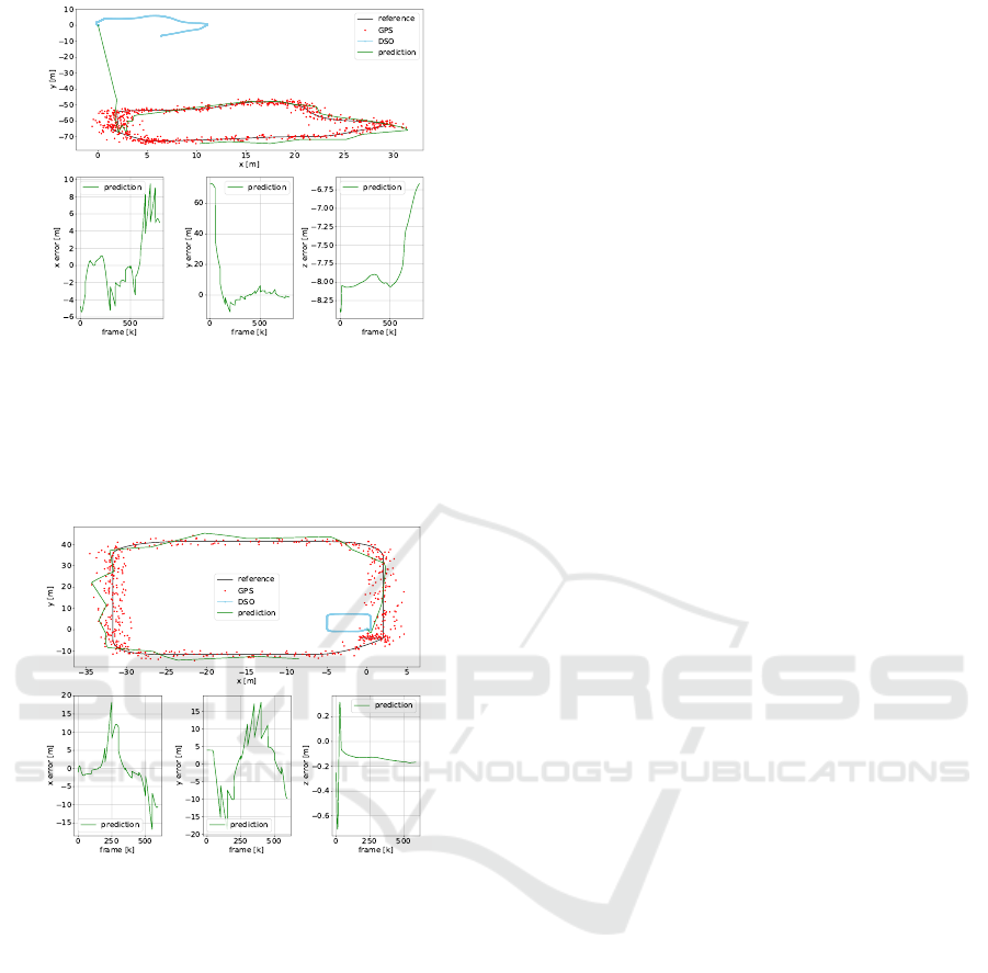
Figure 10: Scenario 3: GPS position and DSO velocity up-
dates, every 50th frame
Top: 2D trajectory visualizing x and y coordinates
Bottom: RMSE position error of prediction in x, y and z.
5.4 Scenario 4: SceneCity Loop
Figure 11: Scenario 4: GPS position and DSO velocity up-
dates, every 50th frame
Top: 2D trajectory visualizing x and y coordinates
Bottom: RMSE position error of prediction in x, y and z.
The fusion of raw GPS position and DSO velo-
city measurement updates for scenario 4 is depicted
in Figure 11. GPS readings are provided at every 50th
frame. Due to the slow refresh rate of GPS, the pre-
dicted trajectory is smoothed, causing it to approxi-
mate an ellipse and thus vigorously cut corners. This
is not desirable in urban environments.
To summarize, this urban scenario consisting of a
loop may cause the linear Kalman filter to overshoot
in parts where the camera turns, similar to the Venice
dataset. Most notably, each curve did cause the pre-
diction to deviate away a bit more from the true track.
Although the corner radius can be considered having
a usual size, their non-linear characteristic did still de-
teriorate the prediction.
6 CONCLUSION
Our approach to simulate sensor data and execute the
fusion in Blender provides an attractive way to in-
vestigate both the way DSO operates on a diverse
set of input images and how this influences sensor
data fusion. It was shown that an uncoupled fusion
of DSO and GPS offers a promising way to com-
bine these sensors although the current realization is
still very basic. There are a few improvements to
the system we would like to address in future work.
As most realistic problems in robotics involve non-
linear functions (Kostas Alexis, University of Nevada,
Reno, 2018), the linear Kalman filter is not applica-
ble for these types of motions. An Extended Kalman
Filter (EKF) could solve this by using local lineariza-
tion (Thrun et al., 2005). An alternative may be the
use of an Unscented Kalman Filter (UKF) (Wan and
Van Der Merwe, 2000) or a Particle Filter (PF) (Rui
and Chen, 2001) which could enable a direct compa-
rison of common fusion strategies. Furthermore, the
simulation environment could be extended to real ci-
ties by generating a virtual city model from imagery
of the internet using Structure-from-Motion (SfM) al-
gorithms and GPS trajectories from open map databa-
ses enabling researchers to compare the performance
of fusion with real and synthetic data at the same time.
A detailed evaluation on the effects of sensor errors in
Visual SLAM is another interesting topic where sub-
sequent research may continue.
REFERENCES
Agisoft LLC (2014). Agisoft photoscan. Accessed: 2018-
07-04.
Amirloo Abolfathi, E. (2015). Integrating Vision Deri-
ved Bearing Measurements with Differential GPS for
Vehicle-to-Vehicle Relative Navigation. PhD thesis,
University of Calgary.
Andersson Technologies LLC (2018). Syntheyes. Acces-
sed: 2018-07-04.
Aumayer, B. (2016). Ultra-tightly coupled vision/gnss for
automotive applications.
Blender Contributors (2018). Blender foundation: Libmv.
Accessed: 2018-07-04.
Blender Foundation (2018). blender.org - home of the
blender project - free and open 3d creation software.
Accessed: 2018-07-04.
Capturing Reality (2018). Reality capture. Accessed: 2018-
07-04.
Changchang Wu (2018). Visualsfm : A visual structure
from motion system. Accessed: 2018-07-04.
Choy, C. B., Xu, D., Gwak, J., Chen, K., and Savarese,
S. (2016). 3d-r2n2: A unified approach for single
VISAPP 2019 - 14th International Conference on Computer Vision Theory and Applications
822

and multi-view 3d object reconstruction. In Procee-
dings of the European Conference on Computer Vision
(ECCV).
Czech Technical University (CTU) et. al. (2018). Alice vi-
sion: Photogrammetric computer vision framework.
Accessed: 2018-07-04.
Ehlenbr
¨
oker, J.-F., M
¨
onks, U., and Lohweg, V. (2016). Sen-
sor defect detection in multisensor information fusion.
Journal of Sensors and Sensor Systems, 5(2):337–353.
Engel, J., Koltun, V., and Cremers, D. (2017). Direct sparse
odometry. IEEE transactions on pattern analysis and
machine intelligence, 4.
Engel, J., Sch
¨
ops, T., and Cremers, D. (2014). Lsd-slam:
Large-scale direct monocular slam. In European Con-
ference on Computer Vision, pages 834–849. Springer.
Eslami, S. A., Rezende, D. J., Besse, F., Viola, F., Morcos,
A. S., Garnelo, M., Ruderman, A., Rusu, A. A., Da-
nihelka, I., Gregor, K., et al. (2018). Neural scene re-
presentation and rendering. Science, 360(6394):1204–
1210.
Forster, C., Pizzoli, M., and Scaramuzza, D. (2014). Svo:
Fast semi-direct monocular visual odometry. In Robo-
tics and Automation (ICRA), 2014 IEEE International
Conference on, pages 15–22. IEEE.
Jancosek, Michal and Pajdla, Tomas (2012). Cmp sfm web
service. Accessed: 2018-07-04.
Khaleghi, B., Khamis, A., Karray, F., and Razavi, S. (2013).
Multisensor data fusion: A review of the state-of-the-
art. 14.
Kostas Alexis, University of Nevada, Reno (2018). Lecture
slides - dr. kostas alexis. Accessed: 2018-07-08.
Krombach, N., Droeschel, D., and Behnke, S. (2016). Com-
bining feature-based and direct methods for semi-
dense real-time stereo visual odometry. In Internati-
onal Conference on Intelligent Autonomous Systems,
pages 855–868. Springer.
Marchthaler, R. and Dingler, S. (2017). Kalman-Filter:
Einf
¨
uhrung in die Zustandssch
¨
atzung und ihre Anwen-
dung f
¨
ur eingebettete Systeme. SpringerLink : B
¨
ucher.
Springer Fachmedien Wiesbaden.
Mohanty, V., Agrawal, S., Datta, S., Ghosh, A., Sharma,
V. D., and Chakravarty, D. (2016). Deepvo: A
deep learning approach for monocular visual odome-
try. CoRR, abs/1611.06069.
Mourikis, A. I. and Roumeliotis, S. I. (2007). A multi-state
constraint kalman filter for vision-aided inertial navi-
gation. In in Proc. IEEE Int. Conf. on Robotics and
Automation, pages 10–14.
Mueller, J. and Massaron, L. (2018). Artificial Intelligence
For Dummies. Wiley.
Mur-Artal, R. and Tard
´
os, J. D. (2017). Orb-slam2:
An open-source slam system for monocular, stereo,
and rgb-d cameras. IEEE Transactions on Robotics,
33(5):1255–1262.
Particke, Hiller, Patino-Studencki, Sippl, Feist, and Thie-
lecke (2017). Multiple intention tracking by a genera-
lized potential field approach.
Rui, Y. and Chen, Y. (2001). Better proposal distributi-
ons: Object tracking using unscented particle filter.
In Computer Vision and Pattern Recognition, 2001.
CVPR 2001. Proceedings of the 2001 IEEE Computer
Society Conference on, volume 2, pages II–II. IEEE.
Sch
¨
onberger, J. L. and Frahm, J.-M. (2016). Structure-
from-motion revisited. In Conference on Computer
Vision and Pattern Recognition (CVPR).
Sebastian Thrun, Udacity, Inc. (2018). Artificial intelli-
gence for robotics. Accessed: 2018-07-04.
Thrun, S., Burgard, W., and Fox, D. (2005). Probabi-
listic Robotics (Intelligent Robotics and Autonomous
Agents). The MIT Press.
Usenko, V., Engel, J., St
¨
uckler, J., and Cremers, D. (2016).
Direct visual-inertial odometry with stereo cameras.
In Robotics and Automation (ICRA), 2016 IEEE In-
ternational Conference on, pages 1885–1892. IEEE.
Vijayanarasimhan, S., Ricco, S., Schmid, C., Sukthan-
kar, R., and Fragkiadaki, K. (2017). Sfm-net: Le-
arning of structure and motion from video. CoRR,
abs/1704.07804.
Wan, E. and Van Der Merwe, R. (2000). The unscented
kalman filter for nonlinear estimation. pages 153–158.
Zhai, G., Meng, H., and Wang, X. (2014). A constant speed
changing rate and constant turn rate model for maneu-
vering target tracking. Sensors, 14(3):5239–5253.
B-SLAM-SIM: A Novel Approach to Evaluate the Fusion of Visual SLAM and GPS by Example of Direct Sparse Odometry and Blender
823
