
Efficient Data-Flow Analysis of UML/SysML Diagrams for Optimized
Model Compilation of Hardware-software Systems
Andrea Enrici
1
, Ludovic Apvrille
2
and Renaud Pacalet
2
1
Nokia Bell Labs, Route de Villejust, 91620 Nozay, France
2
LTCI, Télécom ParisTech, Université Paris-Saclay, 75013 Paris, France
Keywords:
Model-Driven Engineering, Static Data-Flow Analysis, UML, SysML, Optimizing Model Compilation.
Abstract:
Growing needs in terms of latency, throughput and flexibility are driving the architectures of tomorrow’s Ra-
dio Access Networks towards more centralized configurations that rely on cloud-computing paradigms. In
these new architectures, digital signals are processed on a large variety of hardware units (e.g., CPUs, Field
Programmable Gate Arrays, Graphical Processing Units). Optimizing model compilers that target these archi-
tectures must rely on efficient analysis techniques to optimally generate software for signal-processing appli-
cations. In this paper, we present a blocking combination of the iterative and worklist algorithms to perform
static data-flow analysis on functional views denoted with UML Activity and SysML Block diagrams. We
demonstrate the effectiveness of the blocking mechanism with reaching definition analysis of UML/SysML
models for a 5G channel decoder (receiver side) and a Software Defined Radio system. We show that sig-
nificant reductions in the number of unnecessary visits of the models’ control-flow graphs are achieved, with
respect to a non-blocking combination of the iterative and worklist algorithms.
1 INTRODUCTION
The evolution of current networks towards their fifth
generation (5G) is dominated by considerable in-
creases in network traffic (10x higher data rates are
expected) and in the flexibility required to answer
to variations in network services and performance.
These two aspects are expected to significantly impact
the architecture of Radio Access Networks (RANs).
A promising evolution of RAN architectures is the
so-called Cloud-RAN (Checko et al., 2015) that con-
sists in moving some signal processings from a set
of geographically distributed base stations to the core
network. From a programmer’s perspective, this im-
plies that signals will be processed by a greater va-
riety of platforms: from Application-Specific Inte-
grated Circuits (ASICs), in base stations, to cloud sys-
tems equipped with both programmable and config-
urable components (CPUs, Digital Signal Processors
- DSPs, Field Programmable Gate Arrays - FPGAs),
in the core network.
The high complexity of these platforms raises
the need for novel programming paradigms, such
as those based on Model-Driven Engineering
(MDE) (Schmidt, 2006; ?). As of today, the process
of generating optimized implementations (i.e., hard-
ware, software or both) from models is still an open
issue. Because of the abstraction level at which they
operate, modeling languages, such as UML/SysML,
can express more complex control-flow interactions
(e.g., hierarchical composition, dispatch/reception
of signals) than traditional programming languages
(e.g., functions in C). In the context of optimizing
model compilers, this raises the need for novel static
analysis techniques. In this paper, we present an
algorithm that reduces the number of unnecessary
visits due to the propagation of partial information to
Control-Flow Graphs (CFGs) of functional views ex-
pressed with UML Activity diagrams, SysML Block
Definition and SysML Internal Block diagrams.
We demonstrate the efficiency of our algorithm for
the reaching definition analysis of models denoted
in DIPLODOCUS (TTool/DIPLODOCUS, 2006),
a UML/SysML profile for the hardware/software
co-design of embedded systems.
In Section 2 we position our contribution with
respect to related work. Section 3 outlines our ap-
proach for model compilation. Section 4 illustrates
our contribution. Section 5 describes the analysis of
UML/SysML functional views for two telecommuni-
cation systems. Section 6 concludes this paper.
84
Enrici, A., Apvrille, L. and Pacalet, R.
Efficient Data-Flow Analysis of UML/SysML Diagrams for Optimized Model Compilation of Hardware-software Systems.
DOI: 10.5220/0007377900840095
In Proceedings of the 7th International Conference on Model-Driven Engineering and Software Development (MODELSWARD 2019), pages 84-95
ISBN: 978-989-758-358-2
Copyright
c
2019 by SCITEPRESS – Science and Technology Publications, Lda. All rights reserved

2 RELATED WORK
Static data-flow model analysis is inspired by pro-
gram analysis techniques (Nielson et al., 2010) and
encompasses solutions for reasoning about the value
and relations (e.g., definitions, use) of data (e.g., Vari-
ables, Objects) that influence the execution of mod-
els, without actually running them. In the context of
UML, only behavioral diagrams (State Machines, Ac-
tivity and Sequence diagrams) are eligible for static
analysis. To the best of our knowledge, we appear
to be the first to propose the use of static data-flow
analysis on UML Activity diagrams and their combi-
nation with SysML Internal Block and Block Defini-
tion diagrams. Similarly, we found no related work
that applies this type of analysis to optimizing model
compilers.
The relevance of data-flow analysis on models is
evident from the amount of work presented at in-
ternational conferences (e.g., MODELS, MODEL-
SWARD). It can be assumed that work such as (Saad
and Bauer, 2013; Schwarzl, C. and Peischl, B., 2010;
Yu et al., 2008; Kienberger et al., 2014; Lai and Car-
penter, 2013) could profit from the algorithm in this
paper to efficiently propagate the results of data-flow
equations in their respective domains.
Most related work are based on the analysis of
Statecharts for software testing (Kim et al., 1999;
Briand et al., 2005; VERIMAG, 2018). The authors
in (Kim et al., 1999) discuss the generation of test
cases, given a set of criteria to be tested, from UML
State Machines. This generation is driven by data-
flow analysis that identifies the pairs of definitions
and uses of variables. The analysis is conducted on
a control-flow graph that is retrieved by transform-
ing the diagrams into Extended Finite State Machines
where hierarchical and concurrent states are flattened.
With respect to our work, communications between
Classes are not considered and broadcast communi-
cations are eliminated when transforming Statecharts
in Extended Finite State Machines. In (Briand et al.,
2005), the main contribution is a technique that guides
the coverage of UML Statecharts for test data selec-
tion in the context of fault detection. The proposed
technique allows to select the best cost-effective data
structure (a transition tree) based on definition-use
pairs of variables. While our control-flow graph is en-
tirely derived by UML/SysML diagrams, the authors
in (Briand et al., 2005) use a special Event Action
Flow Graph that represents events and actions only,
where operation contracts and guard conditions are
expressed in the Object Constraint Language.
The IF toolset (VERIMAG, 2018) is an environ-
ment for the modeling and validation of heteroge-
neous real-time systems that is built upon an interme-
diate representation formalism, called IF. The toolset
includes a translator for input UML Statecharts and
Class diagrams and a static analyzer. The latter oper-
ates on IF representations and supports live variable
analysis, dead code elimination and variable abstrac-
tion. In IF, the main difference with respect to our
contribution is that the functionality captured by in-
put models is executed by software implementations:
mixed hardware/software or purely hardware imple-
mentations are not considered.
The work in (Yu, 2014) describes a static anal-
ysis technique to analyze UML Class diagrams that
include operations specified using the Object Con-
straint Language (OCL) (OMG, 2014). The structure
of a software project is captured with UML Class di-
agrams that are investigated against a set of scenar-
ios representing some desired or undesired behaviors.
This work addresses the needs of verification engi-
neers rather than software developers.
Following the standardization of the Foundational
Subset for Executable UML, fUML, (Seidewitz,
2014; fUML, 2018), many work analyze fUML spec-
ifications of software implementations. In (Malm
et al., 2018) static program analysis is applied to its
textual action language Alf (OMG, 2018). The au-
thors introduce a round-trip transformation chain that
applies flow analysis to Alf specifications and back-
propagates the results of this analysis to Alf programs
for further investigation. The objective of their anal-
ysis is to retrieve information about loop bounds and
infeasible paths in a model to estimate a worst-case
execution time. In (Malm et al., 2018) a model’s ex-
ecution semantics influences both the construction of
the Control-Flow Graph and the algorithm that visits
it. On the contrary, in our work, the visit algorithm
only depends on the graph’s topology.
The authors in (Waheed et al., 2008) propose an ap-
proach to build a data structure that identifies all the
associations between definitions and use (DU) of vari-
ables within states of an input UML State Machine.
Statecharts are specified with the abstract syntax of
the UML Action Specification Language (Mellor and
Balcer, 2002). An input Statechart is parsed, its con-
trol flow graph is extracted and stored in an adjacency
matrix that is traversed to identify all the DU pairs.
The authors also propose mapping rules that allow
their approach to be reused with virtually any con-
crete syntax of the UML Action Specification Lan-
guage. However, no effective analysis is proposed nor
applied on the DU pairs (e.g., dead "code" elimina-
tion).
The work in (Aldrich, 2002) performs coverage
analysis on MATLAB state diagrams in order to es-
Efficient Data-Flow Analysis of UML/SysML Diagrams for Optimized Model Compilation of Hardware-software Systems
85

tablish completeness and consistency with respect to
design requirements. It forms the core of the Model
Coverage Tool that is commercially available in the
Simulink Performance Tools developed by the Math-
works Inc. For each state diagram’s block, the au-
thor retrieves the control flow of behaviorally equiva-
lent implementation code. When modeling constructs
do not have a unique code implementation, the author
suggests to choose a coverage requirement that guar-
antees full coverage in all of the likely implementa-
tions. A fundamental difference between our work
and (Aldrich, 2002) is that the latter considers anal-
ysis and coverage techniques after models have been
translated in code, not as part of the code generation
process itself. This can lead to discrepancies between
the model’s behavior and its implementation code due
to optimizations performed by the code generation en-
gine (e.g., inlining, dead code elimination).
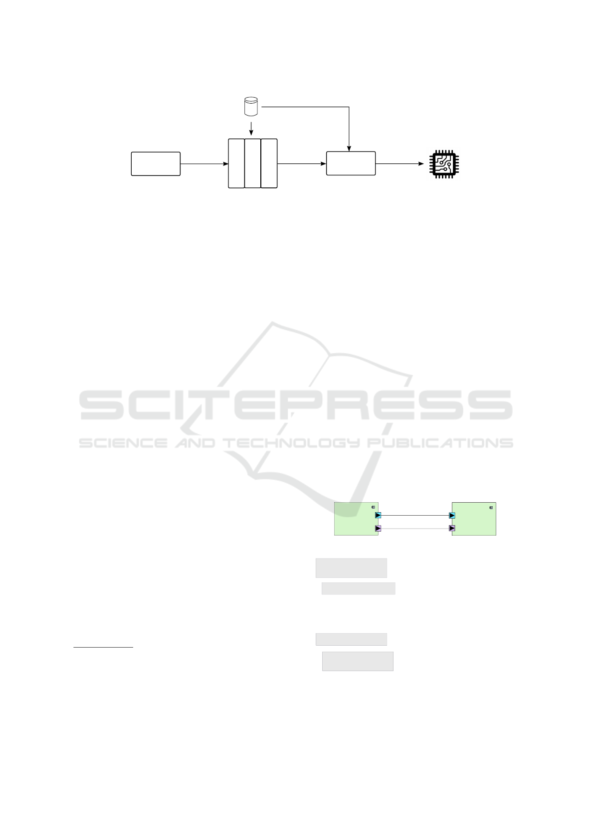
3 MODEL COMPILATION
The methodology that we follow to generate op-
timized software from executable models at Elec-
tronic System Level of abstraction (Gerstlauer et al.,
2009) is shown in Fig. 1. In the context of our re-
search, we develop control software that executes as
an application in the user-space of a Real-Time Op-
erating System. This software governs the execu-
tion of data processing and transfer operations that
can be implemented as both hardware and/or soft-
ware modules. For this reason, we model a system
with a combination of UML/SysML diagrams, rather
than UML only. With respect to the C program-
ming language
1
, UML/SysML diagrams express par-
allelism explicitly. They offer richer constructs than
concurrent languages (e.g., Synchronous Data Flow
(SDF) (Lee and Parks, 1995) and Kahn Process Net-
works (KPN) (Kahn, 1974)) that do not capture the in-
ternal behavior of computations and communications.
In Fig. 1, input specifications are created in
DIPLODOCUS (TTool/DIPLODOCUS, 2006), step
(1). Here, a system is captured in terms of its func-
tionality (i.e., behavior), the architecture of its target
platform (i.e., the services and topology of available
resources) and the communication protocols (e.g.,
DMA transfers). In this phase, models are used as
the primary artifact for software development. They
are created, edited and debugged (e.g., formal ver-
ification, simulation, profiling) until legal specifica-
tions are obtained that respect some desired con-
1
As C is the most widely used programming language
for the development of signal-processing applications, we
consider it the reference to which we compare our research.
straints (e.g., throughput, latency, power consump-
tion). This is similar to the way code is created,
edited and debugged in Integrated Development Envi-
ronments (IDE) such as Eclipse CDT (Eclipse CDT,
2018). Subsequently, model-based specifications are
compiled into C code, step (2) in Fig. 1, by an op-
timizing compiler. The structure of the latter is in-
spired by those for programming languages (Torczon
and Cooper, 2007) and includes a front-end for pars-
ing and analysis, a middle-end for optimization and a
back-end for code generation. To target Cloud-RAN
systems, our model compiler is designed for multi-
processor architectures with heterogeneous compu-
tation, communication and storage units that can be
both shared or distributed. At the output of the model
compiler in Fig. 1, code becomes the primary artifact
for software development as in classical software en-
gineering. We specify to the reader that the control
software generated by the compiler does not include
the algorithmic part of computations and communi-
cations. For this part, we rely on external platform-
specific libraries (e.g., I/O specific code, platform-
specific code for OS or middleware).
The desired implementation is produced by means
of a final translation, step (3) in Fig. 1. This imple-
mentation can be realized entirely in software (e.g.,
an application running on top of an Operating Sys-
tem) or in hardware (e.g., a hardware IP-based de-
sign) or both (e.g., some functionalities are executed
by a general-purpose control processor and some are
accelerated in hardware). Different translators must
be used accordingly: Computer Aided Design (CAD)
toolsuites (e.g., Xilinx Vivado High Level Synthesis)
or traditional programming-language compilers (e.g.,
GNU/gcc/g++, Clang).
4 STATIC MODEL ANALYSIS
In this section, we propose a framework for solving a
large class of data-flow analysis problems (e.g., reach-
ing definitions, available expressions, live variables)
for functional views expressed with UML Activity
(AD) and SysML Block diagrams (i.e., SysML Block
Definition and Internal Block diagrams - shortened to
BDs). This framework is implemented in the optimiz-
ing model compiler’s frontend of Fig. 1.
From the viewpoint of program analysis tech-
niques, references to UML Activities via Invocation-
Actions resemble the way procedures interact in the
C language. Thus, existing techniques for program
interprocedural analysis (Reps et al., 1995; Jhala and
Majumdar, 2007) can be reused to examine both syn-
chronous and asynchronous invocations of Activities.
MODELSWARD 2019 - 7th International Conference on Model-Driven Engineering and Software Development
86
Library of
platform-specific
functions
(3) Program
translation
Executable
implementation
Model-based
specifications
(2) Optimizing
model compiler
Code-based
specifications
Front-end
Middle-end
Back-end
(1) Model
based
development
Figure 1: The software development flow of executable implementations from system-level models.
However, the execution semantics of an Activity cor-
responds to that of a whole C program rather than
a single procedure. Novel techniques are needed
to efficiently analyze the effects of modeling con-
structs for the exchange of data among Activities
such as SendObjectActions and ReceiveObjectAc-
tions. These Actions result in numerous interactions
among CFGs that increase the amount of information
to be propagated when analyzing models. This is es-
pecially the case when data is exchanged through the
Ports of SysML BDs. As the rules to exchange data
through Ports can be specified by dedicated Protocol-
StateMachines, a sound and precise analysis frame-
work must include the CFGs corresponding to these
protocols.
4.1 The Control-Flow Graph Creation
The CFG that results
2
from the composition of UML
ADs and SysML BDs is a directed graph G
∗
=<
N
∗
, E
∗
>. G
∗
is a supergraph that consists of a set of
control flowgraphs N
∗
= {G
1
, G
2
, ..., G
n
}. In each
graph G
i
=< N
i
, E
i
>, nodes N
i
are the modeling con-
structs of an Activity and edges E
i
are the Activity’s
ControlFlowEdges. One of these flowgraphs, G
source
,
represents the source Activity that injects samples
and is the functional view’s entry point
3
. At least
one sink node is also present, G
sink
that collects the
samples that have been processed. E
∗
is the set of
superedges that correspond to Relationships among
SysML Blocks (the control flowgraphs in N
∗
).
Each Activity’s CFG G
i
has a unique start node
(i.e., UML InitialNode) and can have multiple exit
nodes (i.e., UML ActivityFinalNode and FlowFi-
nalNodes). Remaining nodes represent the modeling
2
We do not describe how to create a CFG from the graph
of a UML AD. Thanks to the separation between Tokens
and Edges of different types, a CFG can be obtained by vis-
iting the AD’s graphical representation and filtering out un-
desired nodes and edges.
3
This is similar to the CFG for the main() procedure in
the C programming language.
statements (e.g., Actions) and predicates of an Activ-
ity (e.g., ControlNodes). In addition to the ordinary
intra-graph edges that connect the nodes within such
a CFG, special inter-graph edges are created for each
pair SendObjectAction-ReceiveObjectAction. Here,
we distinguish two cases according to the presence
or absence of a ProtocolStateMachine. In case data
is not exchanged through a Port or is exchanged
through a Port that lacks protocol specifications, an
asynchronous call edge is added, in the CFG, from
the SendObjectAction’s node to its matching Re-
ceiveObjectAction’s node. In case of the presence
of a ProtocolStateMachine, instead, we add the pro-
tocol’s CFG to G
∗
and connect it to the caller Ac-
tivity’s CFG by means of a pair of synchronous call
and return edges. A return node is also added to
the caller Activity’s CFG as the immediate succes-
sor of the calling node, in order to retrieve the ex-
changed data. The resulting CFG is similar to the
one of a C program with synchronous procedure calls
and allows to reuse techniques from interprocedural
program analysis. By way of example, the upper
producer_DMATransfer( _numSamples, _data[], _srcAddress, _dstAddress )
{
array[] <- _data[];
counter = _numSamples;
j = 0;
for( i = counter; i > 0; i-- ){
DMA.transfer( array[ j ] );
j++;
}
return;
}
consumer_readFromDMA( _numSamples )
{
i = 0;
counter = _numSamples;
while( counter > 0 ) {
array[ i ] = DMA.read();
i++;
counter--;
}
return array[];
}
B2
B1
B3
B4
Producer
Activity
Consumer
Activity
Figure 2: The SysML BD for a pair of Activities (upper
part) and the pseudo-code of the Ports’ ProtocolStateMa-
chines for a DMA transfer (lower part).
Efficient Data-Flow Analysis of UML/SysML Diagrams for Optimized Model Compilation of Hardware-software Systems
87

processing
processing
for(...)
return
B1
B2
SendAsyncObject(var1)
CallToPortProtocol()
return from call node
processing
processing
ReceiveAsyncObject(var1)
CallToPortProtocol()
return from call node
while()
return
B3
B4
producer_DMATransfer(...)
consumer_readFromDMA(...)
Producer
Consumer
Figure 3: The CFGs for the Activities and ProtocolStateMa-
chines in Fig. 2. Nodes B1-B4 correspond to the code snip-
pets highlighted in gray in Fig. 2.
part of Fig. 2 shows the SysML BD for a functional
view where a pair of producer-consumer Activities
(inside the Blocks) exchange data through Ports. The
blue Ports in Fig. 2 exchange data via a DMA trans-
fer and make use of ProtocolStateMachines whose
pseudo-code is shown below the diagram. The ex-
change of data on purple Ports in Fig. 2, instead, uses
no ProtocolStateMachine. Fig. 3 shows the CFGs
for the Activities (rectangular nodes) and the Proto-
colStateMachines (circular nodes). In Fig. 3, dotted
edges represent inter-Activity dependencies, whether
synchronous or asynchronous. The dotted edge be-
tween SendAsyncObject and ReceiveAsyncObject
corresponds to the Relationship between the purple
protocol-less Ports in Fig. 2. Dotted lines are also
used to represent the synchronous call and return
edges between and Activity’s CFG and the Proto-
colStateMachine’s CFG of its associated Port. For
the sake of simplicity, in Fig. 3 we abstracted mod-
eling statements that do not reference Activities or
exchange data between Activities with cloud-shaped
nodes.
4.2 The Control-flow Graph Analysis
Static analysis is computed by propagating data-flow
information (facts) along the CFG’s edges according
to the edges’ transformation functions that account for
the semantics of nodes. Visitation algorithms stem
from two common approaches: the iterative search
and the worklist algorithms. In the iterative search
(Algorithm 1), each node is visited once. If any
changes occur in the output information to be propa-
gated, then dependent nodes are visited iteratively un-
til there are no further changes. In the worklist visit
(Algorithm 2), all the edges are stored in a list. An
edge is popped out and information propagated to its
destination node: if any changes occur then its succes-
sors
4
are pushed into the list. This exploration repeats
until the worklist is empty.
The worklist algorithm immediately propagates
changes to neighboring nodes by pushing their edges
into the list and examining them in the next itera-
tion. However, a complete visitation of all nodes
may require multiple visits of the same node before
new nodes are considered. On the contrary, the itera-
tive search always visits nodes once but it waits until
the next visitation of the entire CFG to propagate a
change.
Algorithm 1: The iterative search algorithm.
1 changed = true;
2 while changed do
3 changed = f alse;
4 for ∀node n do
5 old = out[n];
6 process(n);
7 if old 6= out[n] then
8 changed = true;
9 end
10 end
11 end
Algorithm 2: The worklist algorithm.
1 worklist ← {start edge};
2 while worklist 6= /0 do
3 worklist ← worklist \ e;
4 old = out[e];
5 process(e);
6 if old 6= out[e] then
7 for p ∈ succ[e] do
8 worklist ← worklist ∪ p;
9 end
10 end
11 end
However, the eagerness of the worklist algorithm may
yield poor performance in case of inter-Activity anal-
ysis. In case of context unsensitive analysis, the nodes
of an Activity’s CFG are shared among different Ac-
4
We always imply forward analysis. Predecessors must
be considered in the case of backward analysis.
MODELSWARD 2019 - 7th International Conference on Model-Driven Engineering and Software Development
88

tivity’s references and among inter-Activity depen-
dencies. This results into the nodes of an Activity be-
ing visited multiple times and partial information be-
ing propagated. Ultimately, this leads to an increase in
the analysis running time and processing resources. A
similar issue is described in (Atkinson and Griswold,
2001) for program analysis.
To overcome this issue, Algorithms 1-2 can be com-
bined as in (Atkinson and Griswold, 2001). The iter-
ative search has a more global nature in that, at each
iteration, it computes data flows for all CFG’s nodes.
This makes it a suitable candidate to direct visitations
of the entire supergraph G
∗
. The worklist algorithm,
instead, has a more local nature as it propagates data
flows locally to a node’s successors only (predeces-
sors in case of backward analysis). This makes it an
ideal candidate to visit single Activities’ CFGs.
Nonetheless, because of data flows from inter-
Activity dependencies, this combination does not per-
form well enough for the analysis of UML ADs and
SysML BDs. The iterative algorithm must not prop-
agate local changes from a previous iteration to all
nodes in G
∗
. Similarly, at each visitation, the work-
list algorithm should explore a node’s successors or
predecessors only when information from all its in-
coming edges is available (i.e., information on both
inter- and intra-Activity edges).
As a solution, in Algorithms 3-4 we propose a Com-
bined Iterative Blocking Worklist (CIBW) search. In
Algorithm 3, a first blocking worklist exploration of
all graphs in G
∗
starts, lines 8-10. Subsequently, lines
12-30, blocked Activities are iteratively visited until
no changes occur when data-flow information is prop-
agated. Lines 12-30 in Algorithm 3, describe the it-
erative search on (super)nodes of G
∗
at the level of
abstraction of the whole supergraph. Here, each node
in G
∗
is processed only if the data-flow information
of any of its successors (predecessors in the case of
backward analysis) has changed as indicated by a set
of pending graphs P. Each node is visited exactly
once on each iteration (lines 9 and 16) in order to
retain the fairness of the original iterative approach.
Therefore, an Activity is not visited again before an-
other pending Activity is visited.
An Activity’s CFG is visited by a blocking version of
the worklist search, in Algorithm 4. Here, a worklist
of edges is created, line 2, from the set of unvisited
intra-Activity and inter-Activity nodes. An edge is
denoted as e( n,m ), where n and m are the producer
and consumer nodes, respectively. At lines 4-14, ex-
ploration proceeds like in the classical worklist search
(Algorithm 2). It is suspended at lines 16-19, hence
the name blocking, in case the source node of an inter-
Activity edge has not been visited yet. The Activity
being analyzed is added to the pending list P. Upon
completing the analysis, the Activity is removed from
the pending list P, line 22. Nodes that belong to the
predecessors of this Activity are marked as unvisited,
line 23, if they have already propagated information
to all their successors.
To avoid deadlocks due do cycles in the supergraph
G
∗
, the blocking mechanism (line 16 in Algorithm 4)
does not activate on unvisited dependencies that origi-
nate from Activities whose distance from G
∗
’s source
is greater than the one of the currently visited Activ-
ity. This distance is computed at line 3 in Algorithm 3
by measuring the shortest path.
Algorithm 3: The CIBW algorithm.
Input : G
∗
=< N
∗
,E
∗
>
Global parameters: visited[], analysis[], P
Output : analysis[ ]
1 foreach n ∈ N
∗
do
2 analysis[ n ] = ⊥;
3 compute_distance( n );
4 foreach node ∈ n do
5 visited[ node ] = f alse;
6 end
7 end
8 foreach n ∈ N
∗
do
9 blocking_worklist( n );
10 end
11 changed = true;
12 while changed do
13 changed = f alse;
14 foreach p ∈ P do
15 old = analysis[ p ];
16 blocked = blocking_worklist( p );
17 if blocked then
18 changed = true;
19 end
20 else
21 if old 6= analysis[ p ] then
22 changed = true;
23 foreach s ∈ succ( p ) do
24 P ← P ∪ s;
25 mark_nodes_as_unvisited( s );
26 end
27 end
28 end
29 end
30 end
4.2.1 Performance Gain
In the CFGs that we consider, data exchanges that
are associated to ProtocolStateMachines are equiv-
alent to procedures in traditional program analy-
sis. Thus, we evaluate the gain of the CIBW al-
gorithm when Ports are not associated to Protocol-
StateMachines (e.g., edge SendAsyncObject(var1)
Efficient Data-Flow Analysis of UML/SysML Diagrams for Optimized Model Compilation of Hardware-software Systems
89

Algorithm 4: The blocking worklist algorithm.
1 Function
blocking_worklist( Activity CFG b = <
N
b
, E
b
>):
2 worklist = create_worklist();
3 while !empty( worklist ) do
4 e( n, m ) ← worklist.pop();
5 if n ∈ N
b
, m ∈ N
b
then
6 if tr ans
n
( analysis[ n ] ) 6v
analysis[ m ] then
7 analysis[ m ] ← analysis[ m ] t
trans
n
( analysis[ n ] );
8 visited[ n ] = true;
9 visited[ m ] = true;
10 foreach p ∈ N
b
, p ∈ succ{ m }
do
11 worklist.push( e( m, p ) );
12 end
13 end
14 end
15 else
16 if n ∈ N
b
0
, m ∈ N
b
, b
0
6=
b, distance(N
b
0
) ≤
distance(N
b
), visited[ n ] ==
f alse then
17 P ← P ∪ b;
18 return true;
19 end
20 end
21 end
22 P ← P \ b;
23 mark_predecessors_as_unvisited( b );
24 return false;
25 End function
- ReceiveAsyncObject(var1) in Fig. 3). In Eq. 1,
this is given by the ratio between the number of visits
of the CFG’s nodes N .
g = 1 −
N
blocking worklist
N
non−blocking worklist
= 1 −
N
bw
N
nbw
(1)
This gain can be expressed analytically only for
graphs with a fixed topology (see Section 5). Nev-
ertheless, a generic gain can be expressed, Eq. 2, in
terms of the unnecessary number of visits N
u
that
are performed by the non-blocking worklist for each
node n that receives an inter-Activity edge. Unnec-
essary visits are those that propagate partial informa-
tion without considering updates from inter-Activity
edges. N
u
is zero in two cases. If n has no succes-
sors or if no path exist, from the the Activity’s Ini-
tialNode to n, whose nodes operate on the same data
set (Variables and/or Objects) as n, D
n
. In all other
cases, N
u
is different from zero and depends on two
factors: (i) the number of n’s successors that operate
on D
n
and (ii) the type of paths (acyclic or cyclic) that
these successors belong to.
g =
N
u
N
bw
+ N
u
where N
nbw
= N
u
+ N
bw
(2)
The value of N
u
is given by Eq. 3, for the succes-
sors (predecessors) of a node n that receives an inter-
Activity edge. These successors (predecessors) are
visited either once, if they belong to a linear path, or
k
p
times, one per each iteration, if they belong to a
cyclic path. The coefficient k
p
is defined by the num-
ber of iterations that are necessary to reach the analy-
sis’ fixed point (e.g., fixed point in a lattice).
N
u
=
∑
∀ path p ∈ CFG, i ∈ p
v
p
i
v
p
i
=
(
1 D
i
= f (D
n
), i /∈ cycle
k
p
D
i
= f (D
n
), i ∈ cycle
(3)
In Eq. 3, i indexes nodes n’s successors (predeces-
sors), D
i
denotes the data set on which the i-th node
operates and D
n
the data set onto which n operates. A
path p is defined as a succession of nodes that starts
either at the Activity’s InitialNode or at node n. A
path p can terminate at an ActivityFinalNode or at
a FlowFinalNode or at n itself or at any other node
m that receives a different inter-Activity edge. From
this definition and from Eq. 3, it follows that the num-
ber of unnecessary visits on a given path p, N
u
p
, is
comprised between L
p
, in case p is a linear path, and
k
p
×L
p
, in case p is cyclic, where L
p
is the number of
nodes in p that operate on the data set D
n
. The total
number of unnecessary visits is given by the sum on
all paths p, recursively if nested paths are present in
the Activity’s CFG.
4.2.2 Discussion
The CIBW algorithm and the supergraph G
∗
consti-
tute a framework that produces sound and precise re-
sults for the class of locally-separable problems (also
called "bit-vector" or "gen/kill" problems) such as
reaching definitions, available expressions and live
variables. It can be used for the analysis of a com-
position of UML ADs, regardless of the presence of
a SysML BD. It can be reused in other similar lan-
guages provided some conditions are met: (i) the
absence of global variables and (ii) a pass-by-value
mechanism for the exchange of Objects and Param-
eters among Activities. If these conditions are met,
our framework also extends to profiles that allow syn-
chronous invocations of Activities. In this case, valid
MODELSWARD 2019 - 7th International Conference on Model-Driven Engineering and Software Development
90

paths in G
∗
that result from matching invocation-
return pairs can be analyzed by standard meet over
all valid paths (MVP) techniques from program anal-
ysis.
In case the above conditions do not hold, an engi-
neer wishing to reuse our framework must (i) sepa-
rate the analysis of global data from data that is lo-
cal to Activities and (ii) handle the unbounded set of
pending asynchronous calls. Techniques such as the
one in (Jhala and Majumdar, 2007) can be leveraged
to this purpose.
From an implementation viewpoint, the blocking
worklist algorithm reduces processing time but limits
the deallocation or reuse of the memory that stores the
analysis results for a given node (i.e., data sets recla-
mation). This is the memory that is required to store
entries in analysis[ ] in Algorithm 4. This limitation
is balanced by the fact that data sets for CFGs issued
from models are much smaller than those for CFGs
issued from programs and thus require less memory.
The reason for this is the higher abstraction level of
constructs in modeling languages that may require
multiple basic blocks in programming language in or-
der to capture equivalent behaviors.
5 CASE STUDY
In this section, we demonstrate the effectiveness of
the CIBW algorithm on reaching definition analysis
(i.e., the analysis of the variables’ values). For the
sake of clarity, we first consider the level of abstrac-
tion of single-Activities’ CFGs and ignore the system
supergraph’s topology. We analyze two functional
views of a 5G channel decoder (receiver side, up-
link SC-FDMA, single antenna case, Physical Uplink
Shared channel - xPUSCH). Subsequently, we ana-
lyze the composition of the two decoders in a more
complex system and present performance results that
consider the system supergraph’s topology.
In the DIPLODOCUS (TTool/DIPLODOCUS,
2006) functional views, the semantics of communi-
cations between Activities in given by blocking read
and write Actions. The latter operate on logical First-
In First-Out (FIFO) buffers of finite size. A read op-
eration is blocked until the required items are in the
FIFO. A write operation on a full buffer suspends un-
til items are consumed. The results of the reaching
definition analysis allow to quantify the amount of
data-samples that are produced and consumed by each
signal-processing operation. These values are used by
the compiler’s middle-end to compute a Memory Ex-
clusion Graph (MEG) (Desnos et al., 2014). The lat-
ter is an intermediate representation that captures the
exclusion relations among logical FIFO buffers. It is
used by the compiler’s back-end to allocate physical
memory in the output code.
5.1 Analysis of Individual Diagrams
The algorithm of the 5G decoder is shown in Fig. 4.
We considered two functional views that are represen-
tative of most existing implementations. Both views
have a Controller Activity (not shown here) that gov-
erns the execution of processing operations. In the
first view, that we call sparsely controlled (Fig. 7
and Fig. 5), each operation executes independently
and only receives updates from the Controller con-
cerning the number of samples to process accord-
ing to environmental conditions (Update_EvtIn and
Update_EvtIn2 in Fig. 7 and Fig. 5). This view
targets platforms where control is distributed among
processing elements. In the second view, that we call
centrally controlled (Fig. 8 and Fig. 6), each execu-
tion of an operation is tightly governed by the Con-
troller that, for each schedule, dispatches the amount
of samples to process. This view targets systems
where control functions are centralized to a general-
purpose processor.
We denoted each decoder’s view with a SysML BD
containing 11 SysML Composite Block Components:
1 for each operation in Fig. 4 as well as one Source
and one Sink that respectively emit and collect sam-
ples. For each operation, we created separate Activ-
ities for the processing of control information from
the Controller and the processing of input/output data
samples. This strategy allows to target platforms
where the two Activities can be mapped to different
execution units. Thus, each Composite Block Com-
ponent contains 2 SysML Primitive Block Compo-
nents each containing a UML AD such as the dia-
grams in Fig. 5-8.
Table 1 lists statistics for both views. These num-
bers do not include dependency relations from the
whole decoder’s supergraph and only consider the
analysis of individual diagrams. The numbers of vis-
its in Table 1 are expressed as a function of n
v
that
indicates the number of different values for the con-
trol variables that are dispatched by the Controller to
ADs. In Eq.3, n
v
correspond to k
p
.
In the case of the centrally controlled view, apply-
ing Eq. 1 to the entries in Table 1 results in no gain
for the blocking worklist. For F_ Activities (Fig. 8),
both CIBW and CINBW result in no unnecessary vis-
its because all variables are uninitialized and no in-
formation is propagated to the successors of the first
ReceiveObjectAction. X_ Activities (Fig. 8) are vis-
ited an equal number of times by both CIBW and
Efficient Data-Flow Analysis of UML/SysML Diagrams for Optimized Model Compilation of Hardware-software Systems
91

Descrambling
64QAM
Demodulation
Sub-carrier
demapping
N-point
DFT
LDPC
decoder
M-point
IDFT
Remove
Cyclic
Prefix (CP)
Code
Block
Concatenation
Check and
remove
CRC
RX transport
block
41 code blocks
14 OFDM symbols
from
RF/ADC
QAMDemod
X_QAMDemod
F_QAMDemod
(b)(a)
Figure 4: The block diagram of the 5G channel decoder (a). Each operation is modeled with the DIPLODOCUS SysML
Blocks in (b), with data dependencies (blue Ports) and control dependencies (brown and purple Ports).
size = defaultValue
req
Req_Out(size)
for(;stop == 0;)
inside loop
exit loop
evt
Update_EvtIn(size, stop)
evt
Update_EvtOut(size, stop)
Figure 5: The UML AD for the control part of a generic
operation for the sparsely controlled view.
req
QAMDemod_Req(samplesPerSymbol)
evt
QAMDemod_EvtOut(out_size)
evt
QAMDemod_EvtIn(in_size, out_size, samplesPerSymbol)
Figure 6: The UML AD for the control part of an operation
(F_QAMDemod) for the centrally controlled view.
getReqArg (size)
chl
Samples_ChIn(size)
size
chl
Samples_ChOut2(size)
for(;stop == 0;)
inside loop
exit loop
evt
Update_EvtIn2(size, stop)
chl
Samples_ChIn(size)
size
chl
Samples_ChOut2(size)
Figure 7: The UML AD for the data-processing part of a
generic operation for the sparsely controlled view.
CINBW as no inter-Activity dependency that modi-
fies the value of control Variables is present.
Conversely, in the case of the sparsely controlled
getReqArg (samplesPerSymbol)
chl
QAMDemod_ChOut(samplesPerSymbol*numBitsPerSymbol)
chl
QAMDemod_ChIn(samplesPerSymbol)
for(i=0;i<num_symbols;i = i+1)
inside loop
exit loop
chl
QAMDemod_ChOut(504)
504
samplesPerSymbol*numBitsPerSymbol
Figure 8: The UML AD for the data-processing part of an
operation (X_QAMDemod) for the centrally controlled view.
view, Fig. 7 and Fig. 5, the Controller dispatches two
different values for Variables size and stop which
results in n
v
= 2. The number of visits of the CIBW
algorithm for both X_ and F_ Activities is given by
the sum of the visits for the nodes (excluding nodes
for control statements) outside the loop and those in-
side the loop: 4 + 4n
v
and 2 + 2n
v
respectively. The
number of unnecessary visits for the CINBW algo-
rithm is equal to 3 as node Update_EvtIn2(size,
stop) can propagate the value of size to three suc-
cessors, for a X_ Activity (Fig. 7). It is equal to 1
for a F_ Activity as updates on the value of size
can only be propagated to Update_EvtOut(size,
stop) (Fig. 5). For both types of Activities, the num-
ber of unnecessary visits does not depend on n
v
be-
cause of the absence of further ReceiveObjectActions
in the diagrams’ loops, other than Update_EvtIn(),
Update_EvtIn2().
Without considering the topology of the 5G de-
coder’s supergraph, the CIBW algorithm yields a gain
equal to 1 −
6
7
= 14.3% for each individual F_ Activ-
ity and 1 −
12
15
= 20% for each individual X_ Activ-
ity. As it is evident from Table 1, the small number
of nodes that is typical of CFGs issued from models
MODELSWARD 2019 - 7th International Conference on Model-Driven Engineering and Software Development
92

with respect to those issued from programs justifies
the limited reclamation of data sets that is possible
with the CIBW algorithm.
5.1.1 Generalization
Based on our experience, the topology of the CFGs in
Fig. 5-8 is representative for models of telecommuni-
cation systems. For these topologies, Eq. 4 analyti-
cally expresses a generic gain, derived from Eq. 1, for
the analysis of individual diagrams that do not con-
sider the system supergraph’s topology.
g = 1 −
n
pred
+ n
loop
× n
it
n
pred
+ n
loop
× n
it
+ n
succ
(4)
Here, n
pred
is the number of predecessors of the Re-
ceiveObjectAction, n
succ
the number of its successors,
n
loop
denotes the number of nodes in the loop and n
it
the number of iterations. The behavior of the gain g
can be studied by means of the limits in Eq. 5 and
Eq. 6.
lim
n
it
→0
1 −
n
pred
+
:
0
n
loop
× n
it
n
pred
+
:
0
n
loop
× n
it
+ n
succ
=
n
succ
n
pred
+ n
succ
(5)
lim
n
it
→+∞
1 −
*
0
n
pred
+ n
loop
× n
it
*
0
n
pred
+ n
loop
× n
it
+
:
0
n
succ
= 0
(6)
From Eq. 6, it evinces that when the number of it-
erations is large, the performance of the CIBW de-
generate to that of the CINBW. This is the case when
the Controller dispatches to ReceiveObjectActions a
large number of values for the control variables. Con-
versely, in Eq. 5, the gain is determined by the number
of successor nodes n
succ
that operate on the same data
sets as those received by the ReceiveObjectAction.
Because of the presence of a single ReceiveObjectAc-
tion in the loop body, in Eq. 4-6, we could express the
gain by means of two sets of terms: {n
pred
, n
succ
} that
account for the number of visits at the first iteration of
the CIBW algorithm, while n
loop
×n
it
denotes the vis-
its at successive iterations. We can conclude that the
CIBW effectively reduces the number of visits at the
first iteration only. At successive iterations, the block-
ing mechanism of the CIBW algorithm does not bring
any advantage over the CINBW.
However, if we consider the presence of multiple
ReceiveObjectActions in the loop body, the blocking
worklist reduces the number of visits at all iterations.
The gain can be expressed as in Eq. 7, where n
succ
(r)
is the number of successors of a ReceiveObjectAc-
tion r that operate on the same data set, D
r
. The term
∑
r
n
succ
(r) is the sum of the successors of a given Re-
ceiveObjectAction r, over all ReceiveObjectActions.
n
pred
r
1
is the number of predecessors of the first Re-
ceiveObjectAction r
1
and n
succ
r
1
is the number of r
1
’s
successors.
g = 1 −
n
pred
r
1
+ n
it
× n
loop
n
pred
r
1
+ n
succ
r
1
+ n
it
× ( n
loop
+
∑
r
n
succ
(r) )
(7)
In this case, for a large number of iterations, the gain
does not degenerate to zero, Eq. 8, as opposed to
Eq. 6.
lim
n
it
→+∞
g() = 1 −
n
loop
n
loop
+
∑
r
n
succ
(r)
=
∑
r
n
succ
n
loop
+
∑
r
n
succ
(8)
In Eq. 8, the value of the term
∑
r
n
succ
(r) in the de-
nominator depends on the relative position of Re-
ceiveObjectActions. Its lowest bound is 1 and cor-
responds to a diagram where the loop’s body has only
2 ReceiveObjectActions that are located, one after the
other, at the very end of the loop’s body.
5.2 Analysis of the Control Supergraph
Given the supergraph G
∗
of a system under analysis,
the total gain is computed as the ratio of the num-
ber of visits for all Activities. This gain depends
on the supergraph’s topology. When analyzing the
supergraph of the 5G decoder in Fig. 4, the CIBW
never blocks on incoming ReceiveObjectActions
(e.g., Update_EvtIn in Fig. 6, QAMDemod_EvtIn in
Fig. 5). Because of the linear dependencies among
Activities, Fig. 4, when visiting Activity A
i
, data-flow
facts from Activity A
i−1
are always available and the
test at line 10 in Algorithm 4 always succeeds.
Fig. 9 shows the block diagram of a Software De-
fined Radio system that we designed to sense the fre-
quency spectrum and opportunistically receive infor-
mation on unused frequency bands. This Opportunis-
tic Radio Sensing (ORS) system is composed of a
Controller and the following algorithms:
• An energy detection algorithm called Welch Pe-
riodogram Detector (WPD) that senses the spec-
trum and detects when a given frequency band can
be opportunistically used. It is modeled as a linear
chaining of 6 SysML Composite Blocks that each
contain 2 SysML Primitive Blocks interconnected
as in Fig. 4b. Overall, 5 data dependencies and 10
control dependencies are present.
• Two instances of the 5G decoder in Fig. 4, mod-
eled as described at the beginning of this section.
Efficient Data-Flow Analysis of UML/SysML Diagrams for Optimized Model Compilation of Hardware-software Systems
93

Table 1: Statistics for reaching definition analysis on the two views of the 5G decoder.
Sparsely controlled Centrally controlled
Type of Activity
Diagram
Nb. of CFG
nodes
Nb. of visits
CIBW
Nb. of visits
CINBW
Nb. of CFG
nodes
Nb. of visits
CIBW
Nb. of visits
CINBW
Data processing 9 4 +4n
v
4 +4n
v
+ 3 5 5n
v
13n
v
Control processing 6 2 + 2n
v
2 +2n
v
+ 1 3 3n
v
3n
v
• An algorithm (High Order Cumulants, HOC) that
searches for competing receivers with a higher
priority. It is modeled as a linear sequence of 7
SysML Composite Components that each contain
2 SysML Primitive Components interconnected
as in Fig. 4b. Overall, 9 data dependencies and
16 control dependencies are present.
High Order
Cumulants
(HOC)
5G RX
decoder
5G RX
decoder
Central
Controller
Welch
Periodogram
Detector (WPD)
size, stop
stop
size, stop
size, stop
size, stop
stop
Figure 9: The block diagram of the ORS system. Edges are
labeled with the Variables that they exchange.
In the control-flow supergraph of the diagram in
Fig. 9, the Controller is the source node and each al-
gorithm (5GRX, HOW, WPD) has its own sink node.
Table 2 reports on the results of reaching definition
analysis for the ORS system (the Controller is not in-
cluded). Here, n
v
refers to the number of values of
Variable size that expresses the amount of samples
to process.
Table 2: Statistics for reaching definition analysis on the
specifications of the ORS system.
Signal
processing
algorithm
Nb. of CFG
nodes
Nb. of
visits
CIBW
Nb. of
visits
CINBW
WPD 75 75n
v
75n
v
HOC 105 105n
v
105n
v
5G Decoders 270 270n
v
270n
v
×2
In this system, the Controller first propagates Vari-
able stop with a false value to the 5G decoders (to
start execution). When reception cannot proceed op-
portunistically, the HOC and WPD algorithms com-
municate to the Controller to stop executing the 5G
decoders. Analysis with the non-blocking worklist
CINBW visits the 5G decoders twice: once to propa-
gate stop = false and the second to propagate stop
= true. On the other hand, the CIBW algorithm sus-
pends analysis of the Controller on the incoming de-
pendencies from HOC and WPD. Thus, it propagates
to the 5G decoders both true and false values in a
single visitation. The resulting total gain is given by
g = 1 −
450n
v
720n
v
= 37.5%.
6 CONCLUSIONS
In this paper we presented a framework to perform
static data-flow model analysis on functional views
denoted by UML Activity and SysML Block di-
agrams. These are transformed into control-flow
graphs that also include the behavior of Protocol-
StateMachines for the exchange of data through Ports.
We proposed a visiting algorithm that combines both
iterative and worklist searches as well as a blocking
mechanism that reduces the number of unnecessary
visits that result from the propagation of partial infor-
mation among diagrams.
In future work, we will testbench a richer set of
applications that includes platform-dependent com-
munication protocols with a more complex semantics
(e.g., the DMA transfers in Fig. 3).
REFERENCES
Aldrich, W. (2002). Using Model Coverage Analysis to
Improve the Controls Development Process. In AIAA
Modeling and Simulation Technologies Conference.
Atkinson, D. C. and Griswold, W. G. (2001). Implementa-
tion techniques for efficient data-flow analysis of large
programs. In ICSM, pages 52–61.
Briand, L. C., Labiche, Y., and Lin, Q. (2005). Improving
statechart testing criteria using data flow information.
In ISSRE, pages 104–114.
Checko, A., Christiansen, H. L., Yan, Y., Scolari, L., Kar-
daras, G., Berger, M. S., and Dittmann, L. (2015).
Cloud RAN for Mobile Networks - A Technology
Overview. IEEE Communications Surveys Tutorials,
17(1):405–426.
Desnos, K., Pelcat, M., Nezan, J., and Aridhi, S.
(2014). Memory Analysis and Optimized Allocation
of Dataflow Applications on Shared-Memory MP-
SoCs. Journal of VLSI Sig. Proc. Syst. for Signal, Im-
age, and Video Tech., pages 1–19.
MODELSWARD 2019 - 7th International Conference on Model-Driven Engineering and Software Development
94

Eclipse CDT (Visited on October 2018).
http://www.eclipse.org/cdt/.
fUML (Visited on October 2018).
http://www.omg.org/spec/FUML/1.2.1/.
Gerstlauer, A., Haubelt, C., Pimentel, A. D., Stefanov,
T. P., Gajski, D. D., and Teich, J. (2009). Electronic
System-Level Synthesis Methodologies. IEEE TCAD,
28(10):1517–1530.
Jhala, R. and Majumdar, R. (2007). Interprocedural Analy-
sis of Asynchronous Programs. In POPL, pages 339–
350.
Kahn, G. (1974). The Semantics of a Simple Language for
Parallel Programming. In IFIP Congress, pages 471–
475.
Kienberger, J., Minnerup, P., Kuntz, S., and Bauer, B.
(2014). Analysis and Validation of AUTOSAR Mod-
els. In MODELSWARD, pages 274–281.
Kim, Y. G., Hong, H. S., Bae, D. H., and Cha, S. D. (1999).
Test cases generation from UML state diagrams. IEE
Proceedings - Software, 146(4):187–192.
Lai, Q. and Carpenter, A. (2013). Static Analysis and Test-
ing of Executable DSL Specification. In MODEL-
SWARD, pages 157–162.
Lee, E. A. and Parks, T. M. (1995). Dataflow process net-
work. Proceedings of the IEEE, 83(5):1235–1245.
Malm, J., Ciccozzi, F., Gustafsson, J., Lisper, B., and
Skoog, J. (2018). Static Flow Analysis of the Action
Language for Foundational UML. In ETFA.
Mellor, S. J. and Balcer, M. (2002). Executable UML: A
Foundation for Model-Driven Architectures. Addison-
Wesley Longman Publishing Co., Inc., Boston, MA,
USA.
Nielson, F., Nielson, H. R., and Hankin, C. (2010). Princi-
ples of Program Analysis. Springer.
OMG (2014). The Object Constraint Language Specifica-
tion Version 2.4. https://www.omg.org/spec/OCL/.
OMG (Visited on October 2018). Action
Language for Foundational UML (ALF).
http://www.omg.org/spec/ALF/.
Reps, T., Horwitz, S., and Sagiv, M. (1995). Precise Inter-
procedural Dataflow Analysis via Graph Reachability.
In POPL, pages 49–61.
Saad, C. and Bauer, B. (2013). Data-Flow Based Model
Analysis and Its Applications. In MODELS, pages
707–723.
Schmidt, D. C. (2006). Model-Driven Engineering. IEEE
Computer, 39(2):25–31.
Schwarzl, C. and Peischl, B. (2010). Static- and Dynamic
Consistency Analysis of UML State Chart Models. In
MODELS, pages 151–165.
Seidewitz, E. (2014). UML with Meaning: Executable
Modeling in Foundational UML and the Alf Action
Language. In HILT, pages 61–68.
Selic, B. (2003). The Pragmatics of Model-Driven Devel-
opment. IEEE Software, 20(5):19–25.
Torczon, L. and Cooper, K. (2007). Engineering a Com-
piler. Morgan Kaufmann Publishers Inc., San Fran-
cisco, CA, USA, 2nd edition.
TTool/DIPLODOCUS (2006). http://ttool.telecom-
paristech.fr/diplodocus.html.
VERIMAG (2018). IF: Intermediate Format
and Verification Tool set. http://www-
verimag.imag.fr/article58.html?lang=en.
Waheed, T., Iqbal, M. Z., and Malik, Z. I. (2008). Data Flow
Analysis of UML Action Semantics for Executable
Models. In ECMDA-FA, pages 79–93.
Yu, L. (2014). A Scenario-based Technique to Analyze UML
Design Class Models. PhD thesis, Colorado State
University, Department of Computer Science.
Yu, L., France, R. B., and Ray, I. (2008). Scenario-Based
Static Analysis of UML Class Models. In MODELS,
pages 234–248.
Efficient Data-Flow Analysis of UML/SysML Diagrams for Optimized Model Compilation of Hardware-software Systems
95
