
Empirical Study of Helical Bend Loss in Optical Fibers
Ashitosh Velamuri
1
, Ishan Sharma
2
, Shakti Gupta
2
and Pradeep Kumar Krishnamurthy
1
1
Centre for Lasers and Photonics, Indian Institute Technology Kanpur, Kalyanpur, Kanpur, India
2
Department of Mechanical Engineering, Indian Institute Technology Kanpur, Kanpur, India
Keywords:
Helical Bend Loss, In-plane Bend Loss, Empirical Formula, Analytical Loss Formula.
Abstract:
We propose a method to estimate helical bend loss in optical fibers and extend the method to predict the loss
in a different fiber. In our approach, we consider the in-plane bend loss as the reference and approximate the
loss curve as an exponential function decaying with bend diameter. For in-plane bends, we compute loss over
the bend diameter range of 9.5− 19.5 mm at 1550 nm wavelength. For helical bends, we perform experiments
for the same range of bend diameters and pitch values of 2, 4,5,7 and 10 mm. We extend the exponential
function approximation to the experimental measurements of helically wound fibers and obtain an empirical
formula to estimate the helical bend loss. We find that for a given bend diameter, the bend loss increases
initially with the pitch, attains a maximum value and then decreases below the corresponding in-plane bend
loss. We extend the empirical formula developed for a single fiber with a specific refractive index to evaluate
the helical bend loss in another fiber. We conduct the in-plane bend loss experiments for the new fiber and
repeat the exponential fit and obtain fit coefficients. We calculate the fit coefficients for different pitch values
using empirical formula and predict the helical bend loss. We compare the predicted loss with corresponding
experimental measurements, which are in good agreement.
1 INTRODUCTION
Bending in optical fibers causes the transmitting light
to radiate away from the core, resulting in the power
loss. It is a widespread problem in FTTH applica-
tions, where the fibers are bent at the tight corners
of the wall. In addition to this, the effect of bend-
ing on the field properties such as polarisation and
its intensity is utilized to advantage in few applica-
tions. The circular birefringence exhibited by a he-
lically curved fiber is widely used in fiber optic sen-
sors (Soh et al., 2003). Fibers with helically twisted
cores are designed to achieve single-mode operation
of large mode area fiber lasers (Huang et al., 2016).
Evaluation of helical bend loss in fiber is a topic of
interest for these applications.
The analysis of the fields and computation of the
power loss in helically wound fibers, specified by
bend diameter d and pitch p, involves complex co-
ordinate transformations and tedious numerical cal-
culations. In (Marcuse, 1976b), the author suggest
the replacement of bend radius R in the in-plane bend
loss formula (Marcuse, 1976a), by R/sin
2
θ where θ
is the helix angle given by tan
1
(2πR/p) to obtain he-
lical bend loss. In section 2, we show that the formula
predicts the higher loss for all pitch values and bend
diameters.
In (Frikha et al., 2013), authors performed a me-
chanical modelling of the translational invariant he-
lical structures and theoretically calculated the strain
tensors corresponding to the axial load applied on sin-
gle wire and seven wire strand bent in the form of he-
lix. In (Treyss
`
ede et al., 2013), authors have extended
the analysis of (Frikha et al., 2013) to theoretically
study the wave propagation in a helical waveguides.
A full vectorial modelling of helical core fibers with
the helicoidal coordinates were transformed to carte-
sian coordinates was performed in (Napiorkowski and
Urbanczyk, 2014). A similar transformation was used
in (Wilson et al., 2009), where authors chose numer-
ical path using finite difference time domain (FDTD)
method to solve for the fields in the bent fiber and
studied the propagation characteristics of modes in a
helically curved fiber. A principal disadvantage of
these methods is that they are responsive for simple
step index profiles and become more complicated for
general refractive index profiles. Further, the numer-
ical methods have convergence issues, especially for
large pitch and diameters.
In this paper, we suggest an empirical formula to
evaluate helical bend loss in optical fibers, with arbi-
trary refractive index profiles. In section 2, we de-
Velamuri, A., Sharma, I., Gupta, S. and Krishnamurthy, P.
Empirical Study of Helical Bend Loss in Optical Fibers.
DOI: 10.5220/0007407402290234
In Proceedings of the 7th International Conference on Photonics, Optics and Laser Technology (PHOTOPTICS 2019), pages 229-234
ISBN: 978-989-758-364-3
Copyright
c
2019 by SCITEPRESS – Science and Technology Publications, Lda. All rights reserved
229

scribe the experimental set-up used to measure the in-
plane and helical bend loss. We approximate the bend
loss curve with the diameter as an exponentially de-
clining curve. In section 3, we derive an approximate
analytical formula to compute helical bend loss and
compare the results with the experiments. In section
4 we analyze the experimental measurements of he-
lical bend loss, extend the concept of the exponential
fit to the loss curves of different pitch values and ob-
tain an empirical formula. In section 5, we extend the
empirical method to predict the helical bend loss of a
different fiber. We compare the empirical results with
experiments and validate our approach to be applica-
ble to different fiber types with arbitrary refractive in-
dex profiles.
2 EXPERIMENTAL SETUP
Figure 1: Schematic of the experimental set up used to mea-
sure the bend loss induced in helically wound fibers. PC-
Polarisation Controller, FUT- Fiber Under Test.
Fig. 1(a), shows the schematic of the experimental
set-up used to measure the loss induced in the in-
plane bend, specified by bend diameter d and heli-
cally wound optical fibers, defined by bend diameter
d and pitch p. The light from the laser source, Ag-
ilent N7714A, tuned at 1550 nm wavelength is cou-
pled into the fiber under test (FUT). In experiments,
we used single-mode G652.D fiber spool of 50 Km
length to measure the bend loss induced. In the first
step, we noted the output power reading after FUT us-
ing power meter without applying any external forces
on the fiber. In the second step, we bent the fiber on
mandrels and recorded the output reading. We sub-
tracted the results of the two steps and obtained the
loss induced due to bending alone. First, we per-
formed the experiments for the in-plane bending of
fiber for a diameter range of 9.5 − 19.5 mm. We mea-
sured the bend loss for single turn at each bend diam-
eter thrice and averaged the results.
In Fig. 2 we plotted the in-plane bend loss mea-
sured. The loss obtained through experiments for in-
plane bend is fit to an exponential function of bend
diameter d:
2α[dB/turn] = ae
−b(d−d
0
)
. (1)
10 12 14 16 18
Diameter of bend (mm)
0
2
4
6
8
10
12
Loss (dB/turn)
Experiment
Exponential Fit
Figure 2: Results of loss due to in-plane bending of the
fiber. Also shown is exponential fit of the experimentally
measured losses.
In (1), a and b are the fitting coefficients found by
least-squares fit to the experimental data and d
0
= 9.5
is the offset. For the data in Fig. 2, we found a and
b to be 11.52 and 0.3577 respectively. As expected,
the in-plane bend loss decreases exponentially with
increasing bend diameter (Marcuse, 1976a).
After the completion of bend loss measurement
for in-plane bend, we followed the same procedure
and measured the loss induced in helically wound op-
tical fibers. For helical bends, we considered the same
range of diameters as the in-plane case for the pitch
values 2,4,5,7 and 10 mm. For each bend diameter
and pitch, we bent the fiber for 1 and 3 turns and aver-
aged the bend loss per turn of both the results. Similar
to the in-plane bend experiments, helical bend loss re-
ported here is an average of three readings. In Fig. 3
we plotted the helical bend loss recorded in the ex-
periments, for the pitch values of 2 and 7 mm, along
with the loss computed using the formula given by
Marcuse in (Marcuse, 1976b). From the plots, we can
unequivocally state that the expression in (Marcuse,
1976b) overestimates the loss at all bend diameters
and for all pitch values.
3 ANALYTICAL FORMULA
A general formula to compute loss in a bent fiber is
given by (Schermer and Cole, 2007)
2α =
R
∞
−∞
F(U
x=0
)
H
(2)
ν
(γR)
2
dβ
y
π
2
k
clad
R
(2)
where F(U
x=0
) is the Fourier transform of normalized
mode field distribution of the bent fiber at x = 0, H
(2)
ν
PHOTOPTICS 2019 - 7th International Conference on Photonics, Optics and Laser Technology
230

10 12 14 16 18
Diameter of bend (mm)
10
-2
10
-1
10
0
10
1
10
2
Loss (dB/turn)
Empirical
Experiment
Loss Formula
Marcuse Formula
Schermer Formula
10 12 14 16 18
Diameter of bend (mm)
10
-2
10
-1
10
0
10
1
10
2
Loss (dB/turn)
Empirical
Experiment
Loss Formula
Marcuse Formula
Schemer Formula
Figure 3: Comparison of helical bend loss results, for pitch
value of (a) 2 mm, (b) 7 mm.
is the Hankel function of order ν and second kind,
R is the bend radius and γ is the field decay rate in
cladding. Comparing the modes propagating in a bent
waveguide with a straight waveguide we obtain a re-
lation (Marcuse, 1972):
νφ = β
z
z, (3)
where β
z
is the propagation constant in a bent fiber,
φ is the azimuthal angle, ν is the angular propagation
constant and z is the arc length along the central axis
of bent waveguide. Here, we take z as the arc length
along the helix axis, denoted as SA in Fig. 4, instead
of the axis along planar bend as considered in (Mar-
cuse, 1972), which is given by
z =
Rφ
sinθ
, (4)
where θ helix angle given by:
θ = tan
−1
2πR
p
. (5)
From (4) the angular propagation constant in a he-
lically bent fiber is given by
ν =
β
z
R
sinθ
, (6)
Figure 4: Schematic of the fiber bent in the form of helix.
In (Marcuse, 1976a), Marcuse has expressed the ra-
diation field outside the core of a bent fiber as the
superposition of cylindrical waves and approximated
them with Hankel functions. He expanded the Han-
kel function arguments at the origin, i.e., at x = 0, and
employed the propagation constant and γ at the same
point to calculate the radiation outside the core. In our
work, we make the same approximation but derive a
modified expression of Hankel function for helically
bent fibers with the use of (6). In this derivation, we
use the following approximation for Hankel function
(Marcuse, 1972)
H
(2)
ν
= +i
e
ν(α−tanhα)
p
π
2
νtanh α
, (7)
where,
coshα =
ν
n
2
k
0
R
. (8)
For hyperbolic trigonometric functions, we have the
relation
u = tanhα =
p
cosh
2
α − 1
coshα
. (9)
Substituting (8) in (9) we get
νtanh α ≈
γR
sinθ
. (10)
To evaluate the argument of the exponential function
in (7), we use the relation
α = tanh
−1
u = u +
1
3
u
3
+
1
5
u
5
+ ......., (11)
where u is given by (9). Using (9), we can rewrite
(11) as
α − tanh α =
1
3
u
3
+
1
5
u
5
+ ....... (12)
Substitution of the modified expression for angular
propagation constant (6) and (9) in to (12) gives
α − tanh α = tanh
−1
γ
β
z
sinθ
−
γ
β
z
sinθ
Empirical Study of Helical Bend Loss in Optical Fibers
231

+
1
2
cos
2
θ
γ
β
z
sinθ
β
2
z
β
2
z
− γ
2
sin
2
θ
−
n
clad
k
0
sinθ
β
z
2
γ
β
z
sinθ
x
R
β
2
z
β
2
z
− γ
2
sin
2
θ
(13)
We expand (13) and neglect the higher order terms to
obtain the expresssion
ν(α − tanhα) =
γ
3
R
β
2
z
sinθ
+
1
2
γ
2
cos
2
θ
β
2
z
− γ
2
sin
2
θ
(14)
Substituting (10), (14) into (7), we obtain the
modified expression of Hankel function for helically
bent fibers, which is given by
H
(2)
ν
(γR) = +i
s
2sin θ
πγR
exp
γ
3
R
β
2
z
sinθ
+
1
2
γ
2
cos
2
θ
β
2
z
− γ
2
sin
2
θ
!
. (15)
The analytical loss formula obtained with the
modified Hankel function expression (15) is given by
2α =
sin
1/2
θπ
1/2
κ
2
exp
−
2γ
3
R
stress
β
2
z
sinθ
−
γ
2
cos
2
θ
β
2
z
−γ
2
sin
2
θ
2R
1/2
stress
γ
3/2
V
2
K
m−1
(γr
core
)K
m+1
(γr
core
)
,
(16)
where V is the V -number of the fiber, K
m
is the mod-
ified Bessel function of order m, κ is the field decay
rate in the core region, m is the azimuthal mode num-
ber (m = 0 for LP
01
mode, r), R
stress
≈ 1.28R is the
elasto-optic factor to account for the stresses experi-
enced by the bent fiber.
In Fig. 3 we compared the loss computed from
the analytical formula with the experimentally mea-
sured loss. We observed that the analytical formula
(16) predicts the loss closer to the experiments, com-
pared to the expression given by Marcuse in (Mar-
cuse, 1976b). But the formula still overpredicts the
loss by a finite proportion. We can speculate the er-
ror in Hankel function approximation and the mode
field deformations as the reasons for the differences
still present. In Fig. 3 we also plotted the loss com-
puted with the bend loss formula given in (Scher-
mer and Cole, 2007). In (Schermer and Cole, 2007),
authors expanded the Hankel function arguments at
core-cladding boundary, i.e., at x = a, instead of ori-
gin and derived a corrected loss formula. The recom-
mended formula in (Schermer and Cole, 2007) tends
to underestimate the loss.
4 EMPIRICAL FORMULA
In experiments, we observed the helical bend loss be-
have non-monotonically with the pitch. The loss ini-
tially increases with the pitch, reaches a maximum
value and then starts to decrease. Neither the ana-
lytical loss formula (16) nor the expression given in
(Marcuse, 1976b) show the non-monotonic behaviour
of helical bend loss with the pitch. In this section,
based on the experimental results, we develop an em-
pirical formula to compute loss in helically wound
fibers for given pitch and diameter.
We extended the exponential fit approach, ex-
plained in 2, to the experimentally measured helical
bend loss, where we now treat a and b as functions
of helix pitch p. For each p, we obtain a and b by
fitting experimental loss data as described in the pre-
vious section. Fig. 5 shows the result of this proce-
dure where we plotted a and b as a function of pitch.
We note that a initially increases and then decreases
to p, and b initially decreases and then increases to p.
We obtained an empirical relation between a, b with
p by fitting the data in Fig. 5 by a function of the form
given by
a(p) =
(
m
1
p + a(0), 0 ≤ p ≤ p
peak
m
2
(p − p
peak
) + a(p
peak
), p > p
peak
(17a)
where, m
1
is the increasing slope, m
2
is the decreas-
ing slope, p
peak
is the value of pitch where the slope
changes from m
1
to m
2
.
b(p) =
(
m
3
p + b(0), 0 ≤ p ≤ p
min
m
4
(p − p
min
) + b(p
min
), p > p
min
(17b)
where, m
3
is the decreasing slope, m
4
is the increas-
ing slope, p
min
is the value of pitch where the slope
changes from m
3
to m
4
. We showed the values of
these empirical fit parameters in Table 1.
The result of the fits are shown as solid lines in Fig.
5. With a and b obtained from (17), we calculate the
helical bend loss according to
2α(p, d) = a(p) exp(−b(p)(d − d
0
)). (18)
In Fig. 3, we compared the loss computed using
the empirical formula with the experimental measure-
ments, for pitch values of 2 and 7 mm. We observed
that the empirical loss, predicted using (18), agrees
well with the experiments when compared to the loss
calculated by the analytical formula (16).
PHOTOPTICS 2019 - 7th International Conference on Photonics, Optics and Laser Technology
232
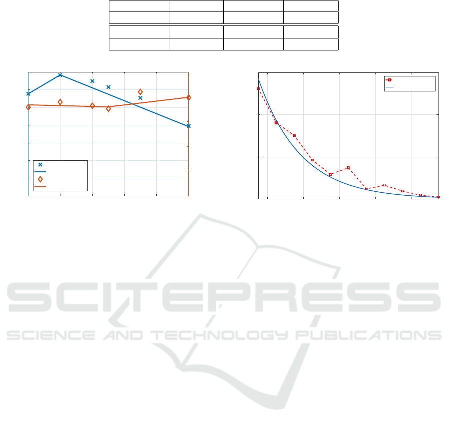
Table 1: Values of empirical parameters used in (17).
m
1
[dB/mm] a(0)[dB] m
2
[dB/mm] p
peak
[mm]
1.07 11.52 −0.73 2
m
3
[/mm
2
] b(0)[/mm] m
4
[/mm
2
] p
min
[mm]
−0.0016 0.37 0.0077 5
0 2 4 6 8 10
Pitch (mm)
0
2
4
6
8
10
12
14
Parameter 'a' (dB)
0
0.1
0.2
0.3
0.4
0.5
Parameter 'b' (1/mm)
a (Experiment)
a (Fit)
b (Experiment)
b (Fit)
Figure 5: Variation of fitting parameters a and b with pitch
p. The solid line is the fitting function given in (17).
5 VALIDATION OF EMPIRICAL
APPROACH
The empirical formula developed here is for single
mode fiber considered in this paper, we can easily ex-
tend our approach to other fiber types. The idea of
the empirical formula is to reduce the computational
complexity involved in the helical bend analysis and
provide a simple method to predict the helical bend
loss induced in an optical fiber from either the numer-
ically calculated or experimentally measured in-plane
bend loss. The in-plane bend loss of optical fibers has
been studied very extensively in literature with sev-
eral closed-form analytical formulae developed (Peng
et al., 2017), (Zheng et al., 2016) and a few numerical
methods using BPM simulations proposed (Schermer
and Cole, 2007). To summarize the discussion, we
can use the empirical parameters given in Table. 1 to
compute helical bend loss in any fiber if we know ei-
ther the experimentally measured or numerically cal-
culated in-plane bend loss.
In this section, we extended our empirical ap-
proach to the different type of fiber to validate our
method being independent of the type of fiber used.
Here, in the second phase of our experiments, we
again used a single-mode G652.D fiber, but from a
different manufacturer with different refractive index
profile. We first performed in-plane bend loss mea-
surements on the new fiber sample and plotted the re-
sults in Fig. 6. Next, we followed the exponential fit
10 12 14 16 18
Diameter of bend (mm)
0
5
10
15
Loss (dB/turn)
Experiment
Exponential Fit
Figure 6: Results of loss due to in-plane bending of the new
fiber sample along with its exponential fit.
procedure, explained in section 2, on the new results
and obtained the fit parameters a and b as 14.28 and
0.42 respectively.
Further, we used the newly obtained values for
a(0) and b(0), the empirical parameters given in Ta-
ble. 1 and calculated the a and b parameters at differ-
ent pitch values. We substituted these values in (18)
and computed the helical bend loss for different pitch
values. To authenticate the obtained loss values, we
performed helical bend loss experiments on the new
fiber sample at 2 and 7 mm pitch and compared the re-
sults in Fig. 7. The close agreement of the empirical
and experimental results validates our empirical ap-
proach to compute helical bend loss of any fiber with
arbitrary refractive index profiles.
6 CONCLUSIONS
In this paper, we have proposed an empirical approach
to predict the helical bend loss in fibers, and extended
the approach to compute bend loss in a different fiber.
We considered the experimentally measured in-plane
bend loss as the reference and approximated the loss
curve with bend diameter as an exponentially decreas-
ing curve ae
−b(d−d
0
)
. We extended the exponential fit
approach to the experimentally measured helical bend
loss, with a and b now considered as the functions
of the pitch and obtained the empirical formula. We
observed that the helical bend loss does not straight
away decrease with the pitch. Instead, it initially in-
Empirical Study of Helical Bend Loss in Optical Fibers
233

10 11 12 13 14 15 16 17 18 19
Diameter of bend (mm)
10
-1
10
0
10
1
10
2
Loss (dB/turn)
Empirical
Experiment
10 11 12 13 14 15 16 17 18 19
Diameter of bend (mm)
10
-1
10
0
10
1
10
2
Loss (dB/turn)
Empirical
Experiment
Figure 7: Comparison of empirical and experimental results
of new fiber sample for pitch values of (a) 2 mm and (b) 7
mm.
creases with pitch reaches a maximum value and then
starts to decline below the corresponding in-plane
bend loss. We developed the formula for a single-
mode fiber with a specific refractive index and then
extended the method to evaluate the bend loss in a
different fiber. We used the obtained empirical pa-
rameters of one fiber and predicted the helical bend
loss in other based on its measured in-plane bend loss.
The empirically computed loss in both the fiber sam-
ples is in close agreement with the experiments. We
have also calculated helical bend loss with an analyti-
cal loss formula, which predicts loss closer to the ex-
periments when compared with the expression given
by Marcuse in (Marcuse, 1976b). Finally, we point
out that the empirical approach proposed in this paper
eliminates the complex coordinate transformations in-
volved in helical bend analyses and gives an uncom-
plicated approach to estimate loss closer to the exper-
iments based on the in-plane bend loss data.
REFERENCES
Frikha, A., Cartraud, P., and Treyssede, F. (2013). Me-
chanical modeling of helical structures accounting
for translational invariance. part 1: Static behav-
ior. International Journal of Solids and Structures,
50(9):1373–1382.
Huang, L., Kong, L., Leng, J., Zhou, P., Guo, S., et al.
(2016). Impact of high-order-mode loss on high-
power fiber amplifiers. JOSA B, 33(6):1030–1037.
Marcuse, D. (1972). Light transmission optics. pages 406–
414.
Marcuse, D. (1976a). Curvature loss formula for optical
fibers. JOSA, 66(3):216–220.
Marcuse, D. (1976b). Radiation loss of a helically deformed
optical fiber. JOSA, 66(10):1025–1031.
Napiorkowski, M. and Urbanczyk, W. (2014). Rigor-
ous simulations of a helical core fiber by the use
of transformation optics formalism. Optics express,
22(19):23108–23120.
Peng, X., Cha, Y., Zhang, H., Li, Y., and Ye, J. (2017).
Theoretical and experimental study of macrobending
losses in coated single-mode fibers. Optical Engineer-
ing, 56(6):066102.
Schermer, R. T. and Cole, J. H. (2007). Improved bend
loss formula verified for optical fiber by simulation
and experiment. IEEE Journal of Quantum Electron-
ics, 43(10):899–909.
Soh, D., Nilsson, J., Sahu, J., and Cooper, L. (2003). Ge-
ometrical factor modification of helical-core fiber ra-
diation loss formula. Optics communications, 222(1-
6):235–242.
Treyss
`
ede, F., Frikha, A., and Cartraud, P. (2013). Me-
chanical modeling of helical structures accounting for
translational invariance. part 2: Guided wave propaga-
tion under axial loads. International Journal of Solids
and Structures, 50(9):1383–1393.
Wilson, J. L., Wang, C., Fathy, A. E., and Kang, Y. W.
(2009). Analysis of rapidly twisted hollow waveg-
uides. IEEE Transactions on Microwave Theory and
Techniques, 57(1):130–139.
Zheng, X., Ren, G., Huang, L., Li, H., Zhu, B., Zheng, H.,
and Cao, M. (2016). Bending losses of trench-assisted
few-mode optical fibers. Applied optics, 55(10):2639–
2648.
PHOTOPTICS 2019 - 7th International Conference on Photonics, Optics and Laser Technology
234
