
Automatic Perception Enhancement for Simulated Retinal Implants
Johannes Steffen, Georg Hille and Klaus T
¨
onnies
Department of Simulation and Graphics, Otto-von-Guericke University, Magdeburg, Germany
Keywords:
Bionic Vision, Retinal Implants, Vision Restauration.
Abstract:
This work addresses the automatic enhancement of visual percepts of virtual patients with retinal implants.
Specifically, we render the task as an image transformation problem within an artificial neural network. The
neurophysiological model of (Nanduri et al., 2012) was implemented as a tensor network to simulate a virtual
patient’s visual percept and used together with an image transformation network in order to perform end-to-end
learning on an image reconstruction and a classification task. The image reconstruction task was evaluated
using the MNIST data set and yielded plausible results w.r.t. the learned transformations while halving the
dissimilarity (mean-squared-error) of an input image to its simulated visual percept. Furthermore, the classifi-
cation task was evaluated on the cifar-10 data set. Experiments show, that classification accuracy increases by
approximately 12.9% when a suitable input image transformation is learned.
1 INTRODUCTION
Due to a severe degeneration of photoreceptors and
other cells within the retina throughout the course of
retinitis pigmentosa (RP), transduction of light into
electrochemical signals and further neural processing
will become significantly limited or even impossible
leading to complete blindness of patients.
For healthy subjects, light is transducted by pho-
toreceptors and subsequently processed within the
retina. Hereby, the signal is forwarded and pro-
cessed throughout the inner nuclear layer consisting
of bipolar-, amacrine-, and horizontal cells and the
ganglion cell layer consisting of multiple types of
ganglion cells with their axons forming the optical
nerve (please see Figure 2 for a schematic overview).
For patients suffering from RP this process is severely
deficient, since photoreceptors and other cells within
the retina degenerate and prevent further process-
Figure 1: Top row: Original images from the cifar-10 data
set. Bottom row: Examples of corresponding simulated
visual percepts by simulating a retinal implant with Alpha
IMS alike parameters.
ing.In later stages of RP, this will lead to complete
blindness.
1.1 Vision Restoration
Recently, new types of medical licensed retinal im-
plants became available that are capable of restoring
the loss of vision caused by RP. Today, the most pop-
ular types of retinal implants are: 1) Epiretinal im-
plants that are placed on top of the retina housing
an array of electrodes stimulating ganglion cells and,
therefore, signals are only indirectly fed into the in-
ner circuitry of the retina (Humayun et al., 2012) and
2) Subretinal implants that are placed below the retina
inside the area of degenerated photoreceptors housing
an array of electrode / photodiode pairs (Stingl et al.,
2013; Stingl et al., 2015) (see Figure 2 for the place-
ment of subretinal implants).
Common to both is a severe loss of visual qual-
ity w.r.t. healthy vision (see Figure 1 for a simu-
lated percept using a retinal implant). The reasons are
manifold: Acuity is significantly lower compared to
healthy vision due to reduced spatial sampling using
only a small amount of photodiodes and transmitting
electrodes (∼ 60 electrodes for epiretinal to ∼ 1600
electrodes/photodiodes for subretinal implants), vi-
sion is limited to grey-scale illumination with lower
contrast, poor spatial sampling due to physical bound-
aries such as an electrode’s size, signal distortions
due to axonal streaks (epiretinal), as well as unwanted
stimulation of nearby cells in an elcectrode’s vicinity.
908
Steffen, J., Hille, G. and Tönnies, K.
Automatic Perception Enhancement for Simulated Retinal Implants.
DOI: 10.5220/0007695409080914
In Proceedings of the 8th International Conference on Pattern Recognition Applications and Methods (ICPRAM 2019), pages 908-914
ISBN: 978-989-758-351-3
Copyright
c
2019 by SCITEPRESS – Science and Technology Publications, Lda. All rights reserved
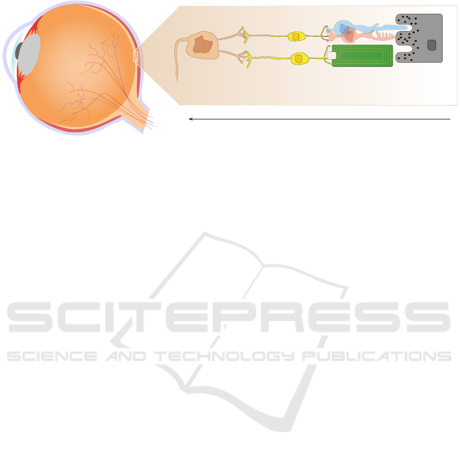
Bipolar cellsGanglion cells
with axons as optical fiber
Epithelium
Signal processing direction
Degenerated photoreceptors
and subretinal implant
Figure 2: Simplified illustration of a human eye ball and a subretinal implant with one electrode/photodiode. Incoming
light is captured using the implant’s photodiode and a cathodic monophasic pulse with a duration of 1 ms is emitted by the
corresponding electrode with a working frequency of 5 Hz to 20 Hz.
1.2 Subretinal Implants
For the purpose of perception enhancement, subreti-
nal implants have two major advantages compared to
their epiretinal counterparts. First, the spatial res-
olution is higher (1600 versus 60 electrodes within
an area of ∼ 13mm
2
) yielding potentially higher vi-
sual acuity and, second, due to their subretinal place-
ment the likelihood to stimulate nearby axons travers-
ing epiretinally, thus, causing axonal streaks, is re-
duced (cf. (Steffen et al., 2018; Beyeler et al., 2017)).
Therefore, we focussed on the automatic perception
enhancements without modelling axonal streaks and
with a number and sizes of electrodes that are used in
subretinal implants.
1.3 Modelling Visual Perception - A
Virtual Patient
For the quantitative and qualitative analysis of visual
percepts from patients with (sub-)retinal implants, ef-
forts were made to model the cascade of process-
ing steps found in neurophysiological experiments.
Beyeler et al. (Beyeler et al., 2017) introduced their
framework pulse2percept for simulating visual per-
cepts with great flexibility w.r.t. a vast amount of
model parameters, e.g., implant type and its specifi-
cations, implant’s position, spatial and temporal sam-
pling, and the underlying neurophysiological model.
We follow the lines of Beyeler et al. by using the
phrase virtual patient and virtual patient’s percept to
refer to a simulated patient and its corresponding vi-
sual perception based on a neurophysiological model.
An example of such subretinal implant simulation can
be seen in Figure 1.
Limitations and Focus of this Work. It has to be
stressed, that the work of (Beyeler et al., 2017) and
(Nanduri et al., 2012) in simulating and modelling vi-
sual percepts is only a coarse approximation of the
neurophysiological processes present in the retinal
circuity. However, the most prominent aspects of
the spatiotemporal information reduction using reti-
nal implants (e.g., a blurred stimulation by spatial
cross-activations) are still captured using the under-
lying simplifications. Thus, methods for the enhance-
ment of visual percepts w.r.t. certain visual tasks need
to deal with these kinds of information reduction and
it is likely, that solutions that adequately tackle those
will still provide good grounds if the underlying neu-
rophysiological model is updated.
Moreover, the exact neural processing within the
retinal circuity is still subject to research, but retinal
implants are present and used today. Therefore, we do
believe that it is necessary and possible to address the
question, whether it is possible to enhance the visual
perception using computer vision methods given an
interchangeable neurophysiological model.
1.4 Outline
As can be seen in Figure 1, the visual perception of
virtual patients with retinal implants is significantly
limited compared to normal vision. Due to spatially
overlapping activations of ganglion cells in the neigh-
bourhood of an electrode and the low spatial reso-
lution, visual acuity is significantly deteriorated and
the percept appears severely blurred. We are inter-
ested to investigate whether it is possible to enhance
the virtual patient’s visual perception, given the phys-
ical bounds and limitations of current retinal implants.
Specifically, we seek a suitable transformation of an
original input stimulus, such that its perceived version
by a virtual patient using a retinal implant looks more
Automatic Perception Enhancement for Simulated Retinal Implants
909
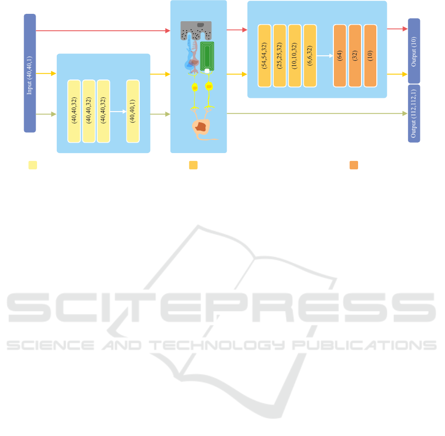
Transformation Network
Neurophysiological
Network
Classification Network
ZeroPadding / Conv2D (3 × 3) / ReLU / BatchNorm FullyConnected / ReLUConv2D (5 × 5) / MaxPooling (2,2) / ReLU / BatchNorm
Figure 3: Overview of the proposed networks. An input image is fed to the transformation network to obtain a suitable
transformation before passing it to the neurophysiological network and finally either to the classification network (yellow
path) or it is compared using a mean-squared-error with a properly resized version of the original input (green path). The
red path indicates the processing flow for the baseline classification of a unaltered visual percept, thus, no transformation is
learned. Please note, that for the output of the classification network a softmax activation is used to obtain class memberships.
similar to its original or provides better grounds for
visual tasks, e.g., object classification.
Following (Steffen et al., 2018), we model the im-
age transformation process as an artificial neural net-
work. However, instead of using a coarse approxi-
mation of the underlying neurophysiological model
of (Nanduri et al., 2012) by a spatial point-spread-
function, we explicitly implement it as a neural ten-
sor network used to simulate the output of electrodes’
stimulations in space and time using a cascade of
convolutions. Modelling the task of perception en-
hancement as a differentiable artificial neural network
allows us to automatically learn image transforma-
tions given arbitrary objective functions in an end-
to-end fashion using gradient descent based back-
propagation.
2 METHODS
We propose to model the neurophysiological signal
processing model of (Nanduri et al., 2012) as a ten-
sor network making it suitable to be plugged into an
artificial neural network enabling end-to-end learning
of various differentiable objective functions. After-
wards, we embed this neurophysiological tensor net-
work inside two artificial neural network architectures
to show its applicability w.r.t. two different tasks: Im-
age reconstruction and image classification.
2.1 Neurophysiological Network
The neural processing of an electrode’s stimulation
yields spatial as well as temporal effects. Since we
are interested in the perceptual enhancement of still
images, an actual input image is fed into the model as
a spatiotemporal signal. We convert the original in-
put images having just one step in time to sequences
with multiple time steps. Specifically, we model an
input image as a spatiotemporal sequence comprising
200ms. This sequence is subsequently transformed
into a pulse train, spatially attenuated as a function
of distance to an activated electrode, and temporally
convolved with multiple gamma functions acting as
low-pass filters throughout time as proposed by Nan-
duri et al. (please refer to (Nanduri et al., 2012; Hor-
sager et al., 2009) for a detailed description).
2.2 Network Architectures
To demonstrate the applicability of the proposed
method, we evaluated two distinct tasks subject to
an image transformation network described below for
perceptual enhancements: First, we seek a transfor-
mation of the original input image, such that its trans-
formed perceptual output is most similar to the orig-
inal input (i.e., trying to reconstruct the original im-
age after the severe information loss introduced by
the retinal implant) and, second, we perform an ob-
ject classification task with 10 classes.
In all of the experiments, we chose the simula-
tion parameters such that they approximately match
the medical licensed Alpha IMS subretinal implant
ICPRAM 2019 - 8th International Conference on Pattern Recognition Applications and Methods
910

(Stingl et al., 2013). Therefore, our simulated reti-
nal implant consists of 40 × 40 electrode/photodiode
pairs, where each electrode has a circular shape with a
radius of 50µm. Electrodes were evenly arranged on a
squared grid with a distance of 70µm w.r.t. their cen-
ters. Pulse trains were generated for a stimuli duration
of 200 ms with monophasic cathodic pulses of 1 ms.
The temporal sampling steps where set to 0.0004 ms.
Thus, one still input image was represented as a pulse
train of shape (40, 40,500), i.e., spatial resolution of
the input at 40 × 40 with 500 simulated time steps.
Pulses occurred at a working frequency of 5Hz. Re-
garding the output of the network, we compromised
between computational complexity and accuracy of
the model by sampling every 25 µm on the retinal sur-
face yielding a spatial output resolution of 112 × 112
px. To obtain a single time step output after the
neurophysiological network we followed the work of
(Beyeler et al., 2017) by extracting the response at the
time step of highest output response. Please note, that
this network has no trainable parameters but has fixed
convolutional kernels as described in (Nanduri et al.,
2012).
2.2.1 Image Transformation Network
The original input image is processed within the im-
age transformation network (see Figure 3 for more de-
tails). Since we are interested in generally suitable
transformations based on a rather small local neigh-
bourhood (and want to avoid transformations based
on image semantics) it consists of only 4 convolu-
tional blocks with kernels of size 3 × 3. The first
three convolutional layers consist of 32 trainable ker-
nels and the last one of 1 to re-obtain the input shape
of the original image.
2.2.2 Image Reconstruction Task
For the task of image reconstruction, the input im-
age is fed into our proposed image transformation net-
work and its output is subsequently transformed to a
simulated percept using the implemented neurophys-
iological tensor network (Figure 3, green path) with
parameters as described in Section 2.2. Since the
output resolution of the transformed visual percept
does not match with the shape of the original input
image (40 × 40 electrodes input, 112 × 112 sampled
positions on the retina as output) the original image
is bi-linearly interpolated to match the output shape
of the neurophysiological network. The dissimilar-
ity between the two is then assessed using the mean-
squared-error.
2.2.3 Classification Task
We choose a simple image classification task with
10 object classes for evaluating the general plausibil-
ity of our system. For the task of object classifica-
tion, we seek for a suitable transformation of the in-
put images, such that their corresponding visual per-
cepts, generated by the neurophysiological network,
will lead to an increased classification accuracy com-
pared to their unaltered counterparts. Therefore, af-
ter feeding the input image to the transformation net-
work and the spatiotemporal network, the output of
the latter is fed to a standard classification convolu-
tional neuronal network consisting of convolutional
blocks and a multilayer-perceptron thereafter (please
refer to Figure 3 for an overview). Here, categorical
cross-entropy is used as the objective function.
3 EVALUATION
3.1 Image Reconstruction
The proposed image reconstruction task was tested
on the popular MNIST data set (Y. LeCun, 1998)
comprising binary images of handwritten digits. This
data set is of particular interest, since due to its clear
figure/ground separation the qualitative assessment
of learned transformations is assumed to be easy to
grasp. Furthermore, the enhancement of visual per-
cepts of digits (and even more letters) is an everyday
visual task that potentially is of great importance for
patients suffering from RP and treated with a retinal
implant. Mean-squared-error was used as the objec-
tive function assessing the dissimilarity of the input
image and its virtually perceived version.
For the training of the network, the training set
comprised 50000 images belonging to 10 classes
of digits (0 − 9). Training was performed batch-
wise (n = 128) for 500 epochs and a validation set
of 10000 different images was evaluated after each
epoch. Standard stochastic gradient descent was used
for optimization with a fixed learning rate of 0.01.
Figure 4a) shows the mean-squared-error (mse)
over time using a logarithmic scale for better visibil-
ity. As it can be seen, training and validation loss
decrease significantly until the validation loss suppos-
edly saturates after around 300 epochs. As a quantita-
tive reference, the baseline mse (without image trans-
formation) throughout the validation set is at 0.067,
whereas it drops to 0.035 after 500 epochs.
For a qualitative visual comparison, the last two
rows of Figure 5 show exemplary results given an in-
put image from the validation set (first column), its
Automatic Perception Enhancement for Simulated Retinal Implants
911
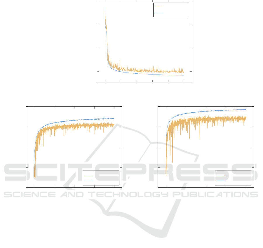
(a)
0 100 200 300 400 500
10
−1.45
10
−1.4
10
−1.35
10
−1.3
epochs
log loss − mse
training
validation
(b)
0 200 400 600 800
0
0.2
0.4
0.6
0.8
epochs
accuracy
training
validation
(c)
0 200 400 600 800
0
0.2
0.4
0.6
0.8
epochs
accuracy
training
validation
Figure 4: a) Loss for image reconstruction task. b) Classification accuracy of the classification task without learning a suitable
transformation. c) Classification accuracy with learned transformation.
learned transformation (second column), the simu-
lated percept of the original image (third column), and
the simulated percept of the transformed image (forth
column). Roughly speaking, the transformation net-
work thins out the original strokes of the digits and
emphasizes visually interesting locations, e.g., cor-
ners, start and end points. This transformation seems
to be adequate, as this will result in visual percepts
looking less blurred and with (subjectively) higher
acuity.
3.2 Classification
Classification as described in Section 2.2.3 was per-
formed using the cifar-10 data set (Krizhevsky et al.,
2009). The data set consists of 60000 training and
10000 validation samples of natural images belong-
ing to 10 different classes. Images were converted to
grey-scale before further processing. This data set is
particularly challenging for the task of perception en-
hancement, since images are often cluttered and often
contain noisy information.
For assessing the quality gain by using a transfor-
mation network, a second model without any image
transformation was trained on the simulated percepts
of the original input images for comparison (Figure 3,
red path).
Training was performed batch-wise (n = 128) for
800 epochs using standard stochastic gradient descent
with a fixed learning rate of 0.01. Validation accuracy
was evaluated after each epoch.
Figure 4b) shows the classification accuracy of the
network without a learned transformation. Validation
accuracy starts to saturate at around 400 epochs and a
final validation accuracy of 62% is obtained. Sim-
ilarly, Figure 4c) shows the classification accuracy
with the learned transformation. Although having the
same characteristics, a slightly higher validation ac-
ICPRAM 2019 - 8th International Conference on Pattern Recognition Applications and Methods
912
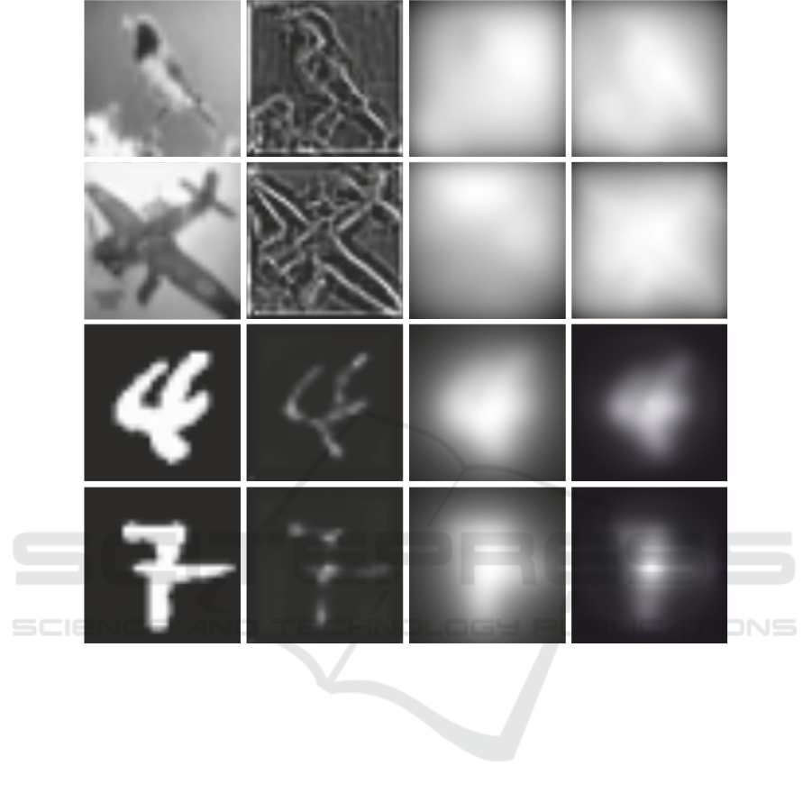
Figure 5: Exemplary results of the classification (first two rows) and the image reconstruction task (last two rows). From left
to right: Original image, learned transformation, simulated percept of the original image, simulated percept of the transformed
image.
curacy of 70% is obtained. For a visual comparison,
the top two rows of Figure 5 show the original input
images (first column), their learned transformations
(second column), the simulated percepts of the origi-
nal images (third column), and the simulated percepts
of the transformed images (forth column). Again, the
learned transformations seem to be adequate, as edges
and contours are emphasized, whereas homogeneous
regions are suppressed.
3.3 Discussion
Although the transformed images do look plausible
(see Figure 5) and significant quality improvements
could be achieved, it remains questionable, whether
the altered images and their corresponding visual per-
cepts will be useful for real patients.
As can be seen in Figure 5, the applied transfor-
mations of the original images seem to enhance the
visual percepts of digits (bottom rows, MNIST) yield-
ing better figure-ground separation, a quality gain re-
garding real and more complex objects on slightly
cluttered background (top rows, cifar-10) is barley no-
table and highly subjective. For further assessment of
bounds, limitations and applicable domains of such
transformations, behavioural experiments need to be
carried out.
Moreover, the model used in our experiments to
describe the retinal signal processing is far from opti-
mal, since it only coarsely approximates the complex
processing of numerous cells within the retina. There-
fore, it is likely that the obtained measurable qual-
ity w.r.t. the classification error and mean-squared-
error is dependent on the underlying neurophysiolog-
ical model. However, due to the fact that the most
prominent aspects of the spatiotemporal information
reduction are captured by the used model of (Nan-
duri et al., 2012), the authors do believe, that the pre-
Automatic Perception Enhancement for Simulated Retinal Implants
913

sented results are indicative for the applicability of
automatically learned transformations for perception
enhancement irrespective of the used neurophysiolog-
ical model.
4 CONCLUSION
By modelling the processing pipeline from an input
image to a percept using artificial neural networks it
is possible to learn input image transformations in an
end-to-end fashion. Therefore, we extend the work
of (Steffen et al., 2018) by implementing the neuro-
physiological spatiotemporal model of Nanduri et al.
(Nanduri et al., 2012) as a tensor network. This al-
lows us to embed the simulation of visual percepts
from retinal implants inside arbitrary artificial neural
networks.
Regarding our goal of perception enhancement,
we proposed an image transformation network that
learns a suitable transformation of input images given
an image reconstruction and classification task. Re-
sults are promising. For both evaluated tasks, a sig-
nificant enhancement was achieved by using our ap-
proach.
However, results have to be seen with caution,
since experiments with real patients or behavioural
experiments have to be conducted to verify its appli-
cability in practical terms. Moreover, within this work
we focussed solely on spatial image transformations,
however, pulse trains may also be altered temporally
providing grounds for extensive further experiments.
Furthermore, using our implementation of the
neurophysiological model of (Nanduri et al., 2012),
our processing pipeline is capable of performing real-
time transformations for upto 30 frames per second.
This will potentially allow to conduct behavioural ex-
periments with healthy subjects using virtual reality
glasses to understand the validity of the assumptions
underlying the image enhancements irrespective of
the validity of the neurophysiological model.
REFERENCES
Beyeler, M., Boynton, G., Fine, I., and Rokem, A. (2017).
pulse2percept: A Python-based simulation framework
for bionic vision. In Proceedings of the 16th Python
in Science Conference, pages 81–88. SciPy.
Horsager, A., Greenwald, S. H., Weiland, J. D., Humayun,
M. S., Greenberg, R. J., et al. (2009). Predicting visual
sensitivity in retinal prosthesis patients. Investigative
Ophthalmology and Visual Science, 50(4):1483–1491.
Humayun, M. S., Dorn, J. D., da Cruz, L., Dagnelie, G.,
Sahel, J.-A., et al. (2012). Interim results from the
international trial of Second Sight’s visual prosthesis.
Ophthalmology, 119(4):779–88.
Krizhevsky, A., Nair, V., and Hinton, G. (2009). CIFAR-10
and CIFAR-100 datasets.
Nanduri, D., Fine, I., Horsager, A., Boynton, G. M., Hu-
mayun, M. S., et al. (2012). Frequency and Ampli-
tude Modulation Have Different Effects on the Per-
cepts Elicited by Retinal Stimulation. Investigative
Ophthamology & Visual Science, 53(1):205–214.
Steffen, J., Napp, J., Pollmann, S., and T
¨
onnies, K. (2018).
Perception Enhancement for Bionic Vision - Prelim-
inary Study on Object Classification with Subretinal
Implants. In International Conference on Pattern
Recognition Applications and Methods, volume 7,
pages 169–177.
Stingl, K., Bartz-Schmidt, K. U., Besch, D., Braun,
A., Bruckmann, A., et al. (2013). Artificial
vision with wirelessly powered subretinal elec-
tronic implant alpha-IMS. Biological sciences,
280(1757):20130077.
Stingl, K., Bartz-Schmidt, K. U., Besch, D., Chee, C. K.,
Cottriall, C. L., et al. (2015). Subretinal Visual Im-
plant Alpha IMS – Clinical trial interim report. Vision
Research, 111:149–160.
Y. LeCun (1998). The MNIST database of handwritten dig-
its. http://yann.lecun.com/exdb/mnist/.
ICPRAM 2019 - 8th International Conference on Pattern Recognition Applications and Methods
914
