
Sitting Assistance that Considers User Posture Tolerance
Daisuke Chugo
1,2
, Masayu Koyama
2
, Masahiro Yokota
1
, Shohei Kawazoe
1
, Satoshi Muramatsu
3
,
Sho Yokota
4
, Hiroshi Hashimoto
5
, Takahiro Katayama
6
, Yasuhide Mizuta
6
and Atsushi Koujina
6
1
Graduate School of Science and Technology, Kwansei Gakuin University, Sanda, Hyogo, Japan
2
School of Science and Technology, Kwansei Gakuin University, Sanda, Hyogo, Japan
3
School of Science and Information and Telecommunication Engineering, Tokai University, Hiratsuka, Kanagawa, Japan
4
Faculty of Science and Engineering, Toyo University, Kawagoe, Saitama, Japan
5
Master Program of Innovation for Design and Engineering, Advanced Institute of Industrial Technology, Tokyo, Japan
6
Service Robot Division, Rt. Works Co., Ltd, Higashinari, Osaka, Japan
hashimoto@aiit.ac.jp, contact@rtworks.co.jp
Keywords: Sitting Assistance, Posture Tolerance, Robotic Walker.
Abstract: This paper proposes a novel sitting assistance robot, which considers the posture tolerance of its user. The
standing and sitting motion are different essentially because the standing is lifting motion against gravitational
force and sitting is posture coordination to sitting position according to the gravity. Therefore, the robot should
lead the patient’s posture within a stable range during sitting and the required performance is different from
standing assistance. However, in previous studies, conventional assistive robots used the sitting motion which
is “reverse” motion of standing. Furthermore, these robots helped patients by using a fixed motion reference
pathway in spite of their original intention, and as the results, these robots failed to assist by confliction
between their intended motion and reference path. Therefore, we propose a novel sitting assistance robot,
which allows its user to move their body within a prescribed degree of posture tolerance during the process
of moving from a standing to a sitting position. Our key findings cover two fundamental research topics. One
is the investigation into posture tolerance during a sitting motion. The other topic is a novel assistance control
algorithm that considers the investigated posture tolerance by combining position control and force control.
A prototype assistive robot, based on the proposed idea was fabricated to help patients sitting down safely
according to their original intention.
1 INTRODUCTION
Activities such as standing, walking, and sitting may
be the most serious and important activities in the
day-to-day lives of elderly people as they lack
physical strength (Alexander et al., 1999; Hughes et
al., 1996). In a typically bad case, an elderly person
who does not have enough physical strength will not
be able to stand up and sit down, and as the result,
they may then be restricted to life in a wheelchair life
or become bedridden (Cabinet Office, Government of
Japan, 2016). Furthermore, once an elderly person
falls into such lifestyle, the decrease in their physical
strength becomes more pronounced due to the lack of
exercise (Hirvensalo et al., 2000). For increasing their
QOL (Quality of Life), they need a personal assistive
robot which enables them to perform daily activities
alone easily even if their physical strength reduces by
aging.
In previous works, many researchers have been
developed assistance devices for a standing motion
(Nagai et al., 2003; Funakubo et al., 2001).
However, these devices are specialized in only a
“standing assistance” and they do not discuss on a
sitting motion. Some previous researchers say a
sitting motion is only “reverse” motion of standing
(Ehara et al., 1996). However, standing and sitting
motion are different essentially because standing is
lifting motion against gravitational force and sitting
is posture coordination to sitting position according
to the gravity. In general, a sitting motion has high
risk for falling down compared with a standing
motion for elderly people (Yoneda, 1998) and it is
difficult to realize a sitting assistance using only
“reverse” motion of standing. Furthermore, a sitting
assistance requires the posture coordination within
stable range, not a force assistance as a standing
assistance because sitting motion follows a gravity
direction. Therefore, the robot should assist the
Chugo, D., Koyama, M., Yokota, M., Kawazoe, S., Muramatsu, S., Yokota, S., Hashimoto, H., Katayama, T., Mizuta, Y. and Koujina, A.
Sitting Assistance that Considers User Posture Tolerance.
DOI: 10.5220/0007956104890496
In Proceedings of the 16th International Conference on Informatics in Control, Automation and Robotics (ICINCO 2019), pages 489-496
ISBN: 978-989-758-380-3
Copyright
c
2019 by SCITEPRESS – Science and Technology Publications, Lda. All rights reserved
489
patients according to their intended sitting motion,
and should help only when their posture are
unsuitable and have high risk for falling down.
In this paper, we propose a novel sitting
assistance robot, which considers the variation in the
range of movements of a patient's body when sitting
from a standing position. To achieve this objective,
we initially investigated the posture tolerance during
the process of sitting down. In this range, patients
can sit down, stably and safely, using their own
physical strength. Secondly, we extend a published
assistance algorithm, (Chugo et al., 2014) which
combines position control and force control, to adapt
to the parameters of the prior investigation into
posture tolerance. Using the proposed algorithm, our
robotic device only assists them to sit down when
necessary.
2 SYSTEM CONFIGURATION
2.1 System Overview
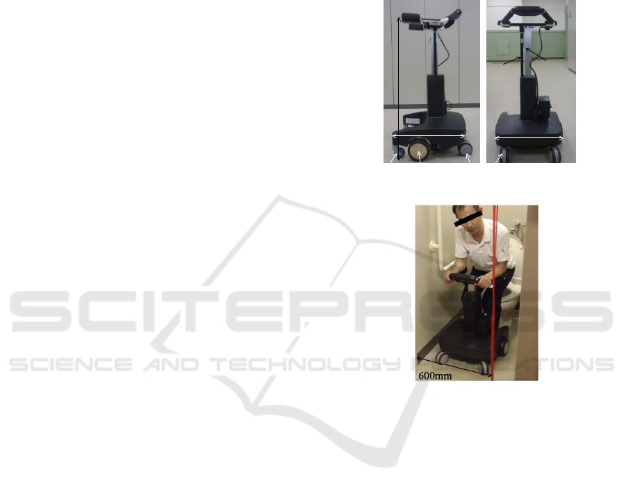
Previously, we have developed robotic walkers which
have a standing/sitting assistance function, (Chugo et
al., 2014; Chugo et al., 2017) and Fig. 1 shows our
recent latest prototype (Chugo et al., 2017). The
design of our proposed assistive device is based on a
powered walker. It has a standing/sitting support
manipulator, which moves the user in an
upward/downward direction. Fig. 1(a)-(b) shows the
default position of the walker’s manipulator at a
standing and walking heights. Its width is 54 cm and
can pass through a typical toilet door with a standard
width of 60 cm (JIS - Japan Industrial Standard –
1526:1997) as Fig. 1(c). Its height is 71.0–96.5 cm
and fits users whose heights are in the range of 145–
160 cm.
To lift down a user, our proposed walker uses a
linear motion DC motor and a gas spring. This motor
can generate a force in the up/downward direction,
whereas the gas spring helps this force in the
up/downward direction. In total, our system can lift a
weight of 40 kg, which is enough to assist someone
in standing or sitting. Using the gas spring, our system
can use a smaller actuator, which means that its
design can be fairly inexpensive. Furthermore, the gas
spring prevents the device from moving suddenly
when the power is down.
The wheels on each side of the walker have an
actuator and an electric parking brake as Fig. 1(a).
The actuated wheels are located in the almost same
position as that of a user and four caster wheels help
in maintaining its balance so that the user can turn
around on the spot when they walk using the device.
The actuator has enough power to control its own
position references, but when a user wants to fix its
position over a long time, they should make use of
the parking brake, because it is a mechanical brake
and its energy efficacy is better than that of the
control scheme containing the actuators.
(a) Side view (b) Front view
(c) Typical situation in the bathroom
Figure 1: Our assistive walker.
2.2 User Interface
A handle, armrest, and controller are provided on the
top of the walker, as shown in Fig. 2(a). There are
force sensors inside the armrests and touch sensors on
the handles. When a user wants to move, they have to
put their arm on the arm-rest and grip the handles.
Using the two sensors, our device judges whether the
user is ready to movement. A gripping switch is
provided on each handle, as shown in Fig. 2(b). This
switch has two input steps that can be changed by the
strength used for the grip. Usually, in emergency
situations, elderly people tend to release the control
switch or push it strongly because of the fear of falling
(Maki et al., 1991). Therefore, we use the two-step
switch in such conditions, as shown in Fig. 2(b), and
our device provides assistance for standing/sitting
only in the case of the first step, whereas in the case
540mm
Gas Spring
Linear
Actuator
965mm
500mm
Actuated Wheel
Front Caster
Rear Caster
ICINCO 2019 - 16th International Conference on Informatics in Control, Automation and Robotics
490
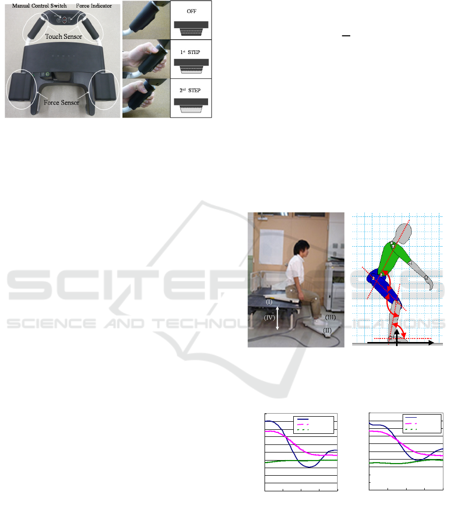
of the second step, our device regards the user as
being in an emergency situation.
(c) Typical situation in the bathroom
Figure 2: Our assistive walker.
3 SITTING MOTION
TORERANCE
3.1 Difference between Sitting Motion
and Standing Motion
From previous works, a sitting motion is same to
“reverse” motion of standing (Ehara et al., 1996). In
our preliminary experiment, we assist a sitting
operation with this reverse motion using our
prototype. Subjects are 6 young people and 2 elderly
people. As the result, all subjects feel fear of falling
and a reverse motion seems to be unsuitable for a
sitting assistance. Thus, in this paragraph, we
analyze a standing motion and a sitting motion
which the nursing specialist recommends.
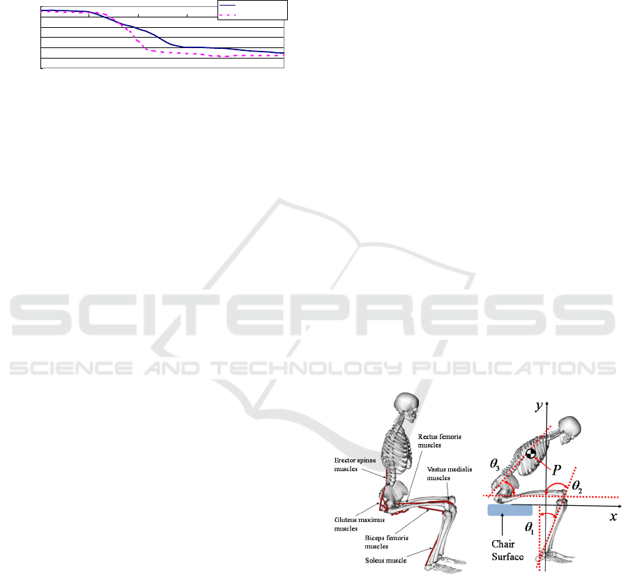
For analysis, we assume a standing and a sitting
motions are symmetrical and we discuss the motion
as movement of the linkages model on 2D plane
(Nuzik et al., 1986). We measure the angular values
among the linkages, which reflects the relationship
of body segments using a motion capture system.
The angular value is derived using the body
landmark as shown in Fig. 3(a). Furthermore, we
measure the position of the center of pressure (COP)
using a force plate system (MG-100, ANIMA Corp.,
Japan) as the index of body stability. The
coordination is shown in Fig. 3(b). Subjects are 6
young healthy people and they operate both motions
based on the recommended motion by the nursing
specialist.
Fig. 4 shows the angular value of each joint and
Fig. 5 shows the position of COP during a sitting
motion. In Fig. 3(b), the Y-axis shows the angular
values of the pelvis and trunk, knee and ankle,
whereas the X-axis shows the movement pattern
(Chugo et al., 2014), which is the ratio of the
standing motion, as shown by (1). Fig. 4(a) is sitting
and Fig. 4(b) is reverse tracks of standing for easy to
analysis.
ˆ
s
t
s
t
=
(1)
In equation 1,
s
t
is the time required for completion
of the sitting down operation and
t
is the present time.
From Fig. 4(a), in a sitting motion, the subject
lowers his trunk at one motion (10-60[%] movement
pattern). On the other hand, in Fig. 4(b), the subject
keeps his trunk around 10-25[%] movement pattern.
In a sitting motion, the subject inclines his trunk and
lowers it earlier than in case of a standing motion.
Furthermore, in a sitting motion, the subject inclines
his trunk larger than in case of a standing motion.
These features are same to previous reports (Dubost
et al., 2005).
(a) Side view (b) Its coordination
Figure 3: Experimental Setup. (I), (II) and (III) are force
plates. We change the height of chair (IV), according to the
subjects.
(a) Sitting motion (b) Its coordination
Figure 4: Angular values of each joint during a motion
recommended by nursing specialists.
From Fig. 5, the tracks of COP in both motions
are different. In a sitting motion, the position of COP
moves slowly than in case of a standing motion. From
θ
1
θ
2
θ
3
X
y
θ
1
θ
2
θ
3
θ
1
θ
2
θ
3
X
y
0
20
40
60
80
100
120
140
160
180
200
0 25 50 75 100
Movement Pattern (%)
Angle (deg
)
P elvis/ Trunk
Knee
Ankle
0
20
40
60
80
100
120
140
160
180
200
0 25 50 75 100
Movement Pattern (%)
Angle (deg
)
Pe lvis /Trunk
Knee
Ankle
Sitting Assistance that Considers User Posture Tolerance
491
tracks of the knee angle in Fig. 4(a), around 60[%]
movement pattern, we can verify that the subject sits
down the target chair. In Fig. 5, the position of COP
moves slowly, especially, around 60[%] movement
pattern. This means the subject puts his hip on the
target chair and moves his weight from his foot to his
hip.
Figure 5: Position of COG during a motion.
In general, a sitting motion does not require the
physical strength as a standing motion, because
sitting is lifting down body movement to from
standing to sitting position according to the gravity.
From these results, we can assume the subject may
lower his trunk with rough path plan and coordinate
his body balance by inclination of his body according
to the process of a sitting motion. Therefore, the
required conditions for sitting assistance are follows.
The robot should allow the patients sitting by
their intended motion in the safety range.
The robot should help the patient if the
patient’s posture are the outside of safety range
and have high risk for falling down.
3.2 Sitting Posture Conditions
In our previous works, we investigate the posture
condition from the viewpoint of body dynamics
during standing (Yokota et al., 2019). However,
sitting and standing are completely different motion
and required conditions for sitting assistance are also
different as the previous paragraph. Considering
above, the sitting posture should be fulfilled by three
conditions from the viewpoint of body dynamics.
Stability condition: The patient should be able
to keep their body balanced in this posture. This
study defines the condition as follows: the
position of the center of gravity (COG) should
be located within the range of the patients
footprint, while keeping the body balanced
during sitting down.
Muscle condition: The patient should be able to
control their body motion in this posture. In
general, the output force generated by muscles,
changes according to the human posture
because the positional relationship between the
muscles and bones changes with the adopted
posture (Chugo et al., 2014). This means an
unsuitable posture cannot generate a sufficient
upper direction output force for proceeding
through with the sitting motion. This study
defines this condition as follows: the output
force of the muscles listed in Fig. 6 should not
exceed the muscle's maximum output during
sitting.
Landing condition: The patient should be able
to control the sitting posture at landing the
seating surface. When landing, the patient
should reduce lowering velocity enough
because strong impact between buttocks and
the seating surface has high risk of injuring
(Yamamoto et al., 2015). This study defines
this condition as follows: the output force of the
muscles should not exceed the muscle's
maximum output when stopping the sitting
motion just before landing the seating surface.
This paper investigates the tolerance level, which
fulfills these three conditions through computer
simulation studies using OpenSim, a human motion
dynamics simulator package. In this simulation, we
used a 3DGait-Model2392 (Opensim documentation,
2018) as human model and modified its body
parameters to fit a typical Japanese elderly person
(Okada et al., 1996). The sitting motion was based on
the references recommended by nursing specialists
(Kamiya, 2005) as shown in Fig. 4(a).
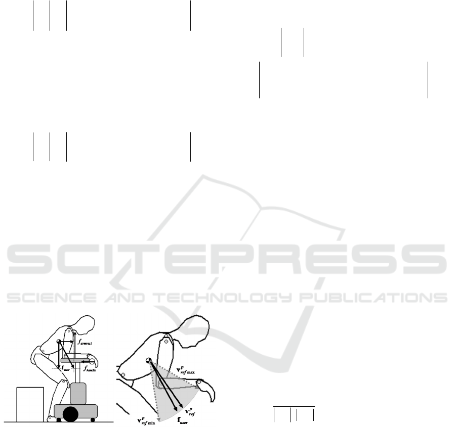
(a) muscles (b) coordination
Figure 6: Human Model.
Generally, the sitting motion consists of three
phases, as shown in Fig. 7(a). Thus, we set a variation
of
±
30[deg] range on the reference posture at the
end of each phase (Postures (A)-(C) in Fig. 7(b)) in
the computer simulation. Note posture (D) is the final
posture and therefore we did not set a variation on this
phase.
-0.5
-0.4
-0.3
-0.2
-0.1
0
0.1
0 20406080100
Movement Pattern (%)
Position of COP (m)
Sitting
Reverse of Standing
ICINCO 2019 - 16th International Conference on Informatics in Control, Automation and Robotics
492
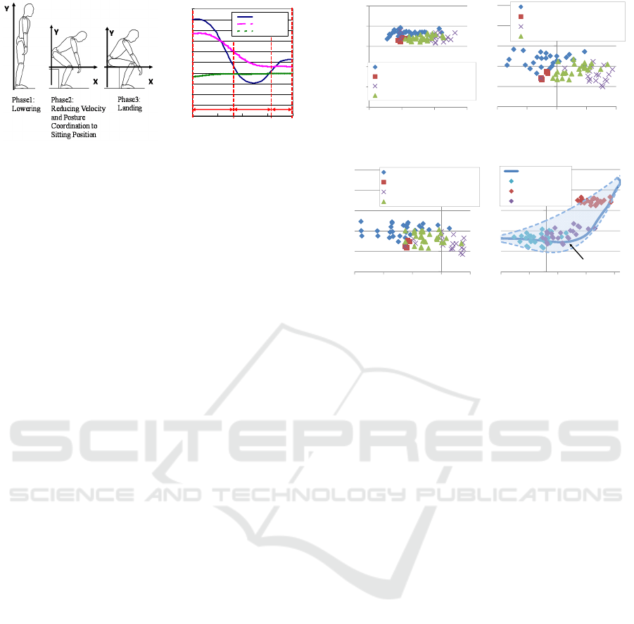
(a) sitting phase (b) references
Figure 7: Simulation Setup.
3.3 Sitting Posture Conditions
Fig. 8 shows the acceptable position of point P,
identified in Fig. 6(b), derived from the computer
simulation. Figs. 8(a), 8(b) and 8(c) show the
acceptable tolerance at 30[%], 50[%] and 70[%]
movement during the pattern of the sitting motion.
Acceptable tolerance fulfills three required
conditions, stability condition, muscle condition and
landing condition.
The sitting motion will be realized within the
tolerance shown in Fig. 8(d) and in this range of
motion, the patient can physically achieve final sitting
posture. The reference tracks are the sitting motion by
Fig. 4(a) and dashed lines shows the tolerance. In
general, a sitting motion has high risk for falling
down to forward direction for elderly people (Maki et
al., 1991) and inclining to forward direction should be
avoided during sitting motion. In Fig. 8(d), there are
the tolerance in backward direction and this result fits
the knowledge of previous study (Dubost et al., 2005).
From this result, it is important to consider the
patient's capable muscle output force in the sitting
posture.
4 ASSISTANCE CONTROL
ALGORITHM
To allow patients to move their intended motion
during sitting down, our controller uses a
combination of damping control and position control.
Damping control can change the strength of assistive
power, thus, it can allow for an offset from the
reference pathway of motion, allowing the patient to
move freely during the sitting down process.
(a) 30% (b) 50%
(c) 70% (d) Investigated tolerance
Figure 8: Simulation Results.
Considering these characteristics, damping
control should be used in the tolerance discussed in
previous section. By contrast, position control is
useful for maintaining body posture, however, its
pathway is fixed. Thus, it is useful when the patient's
posture exceeds the acceptable range.
In our previous work (Chugo et al., 2017), we
proposed an assistance control algorithm based on
the voluntary movement of the patient. We know
from previous research (Yokota et al., 2019) that the
motion of the human body consists of voluntary
movements, which generate the total body motion,
and a posture adjustment action, which keeps the
body stable during motion. This means the robot
should only provide a force that assists the physical
activity in response to the voluntary movement of
the patient, and our proposed algorithm only assisted
the patient when physical strength was required for
doing a voluntary movement. However, the
previously reported algorithm did not consider the
variation in the range of movements during human
motion, so this paper extends this control algorithm
as follows:
First, we defined the body movement vector
P
as (2). This shows the velocity direction of
point P (Fig. 4(a)), which is the COG of the
upper body. The position of P
()
,
ref ref
pp
xy
is a
motion reference point based on the sitting
motion recommended by nursing specialists.
Details regarding the generation of this
0
20
40
60
80
100
120
140
160
180
200
0 255075100
Movement Pattern (%)
Angle (deg
)
Pelvis/Trunk
Knee
Ankle
Phase1 Phase2 Phase3
(A)
(B)
(C)
(D)
0.5
0.6
0.7
0.8
0.9
1
0 0.05 0.1 0.15
Y Position [m]
X Position
[
m
]
Stability Condition is not fulfilled
Muscle Condition is not fulfilled
Landing Condition is not fulfilled
All conditions are fulfilled
0.5
0.6
0.7
0.8
0.9
1
-0.1 -0.05 0 0.05 0.1
Y Position [m]
X Position [m]
Stability Condition is not fulfilled
Muscle Condition is not fulfilled
Landing Condition is not fulfilled
All conditions are fulfilled
0.5
0.6
0.7
0.8
0.9
1
-0.15-0.1-0.05 0 0.05
Y Position [m]
X Position [m]
Stability Condition is not fulfilled
Muscle Condition is not fulfilled
Landing Condition is not fulfilled
All conditions are fulfilled
0.5
0.6
0.7
0.8
0.9
1
-0.08 -0.03 0.02 0.07 0.12
Y Position [m]
X Position [m]
Reference Tracks
Tolerance at 70%
Tolerance at 30%
Tolerance at 50%
Tolerance Range
Sitting Assistance that Considers User Posture Tolerance
493
reference point are given in our previous paper
(Chugo et al., 2014).
()
() () ()
() () ()
ˆ
,
ˆ
0, , , , 1
ˆ
0, , , , 1
ref
p
TT
ref ref ref ref
pp p p
ref
p
ref ref ref ref
pp p p
s
xxsx
yysy
=
==
Pv
x
v
y
(2)
Furthermore, our robot has control references for
each actuator as detailed in (3), which realize the
designed sitting motion (2).
ref
p
x
is the motion
reference for a powered walker and
ref
p
y
is for an
assistance manipulator.
() () ()
() () ()
ˆ
0, , , , 1
ˆ
0, , , , 1
T
T
ref ref ref
ref
rbt rbt rbt
ref
rbt
rbt
ref ref ref
ref
rbt rbt rbt
rbt
xxsx
yysy
==
x
v
y
(3)
Second, we assumed the subject applies all
forces
user
f
at position P because the armrest
and the handle of our assistive robot are
connected rigidly. We can calculate
user
f
from
the force applied to the armrest
armrest
f
and the
handle
handle
f
using force sensors in the robot's
body (Fig. 9(a)) as (4).
()
user armrest handle
=− +fff
(4)
(a) Applied force and body
movement vector
(b) Body motion and its
range
Figure 9: Voluntary movement during sitting.
Third, we assumed the patient also applies a
force for doing a voluntary movement of their
own intention, therefore
user
f
shows a
voluntary component. At the same time, our
controller calculates a motion reference
ref
p
v
at
this posture (Fig. 9(a)) and refers its
investigated tolerance (gray area at Fig. 9(b)).
Our controller evaluates if
user
f
is within the
tolerance at this posture, the patient's motion
fulfills the both conditions as discussed in
section two.
Finally, our robot controls two actuators by (5).
()
()
()
()
0
0
T
upref
upref
rbt
rbt
upref
rbt
ref ref
rbt handle handle rbt rbt
ref ref
rbt armrest armrest rbt rbt
x
v
y
xBf f Kxx
yBf f Kyy
=
−−−−
=
−−−−
(5)
where
upref
rbt
v
is the updated reference value that our
robot actually uses for delivering sitting assistance.
()
,
rbt rbt
xy
is the actual position of the powered
walker and the assistance manipulator of our robot.
B
and
K in (5) are constants used to coordinate the ratio
between the damping and position controls.
0handle
f
and
0
armrest
f
are the forces the patient applies to the
assistance system before the patient sits.
In order to apply the damping control only when
the patient's motion fulfills both the stability
condition and the muscle condition, the coefficient
B
that validates the damping control mode is calculated
as (6).
B will be larger value if
user
f
locates on
the center of the tolerance and in this situation, it
fits
ref
p
v
. By contrast, the position control is always
useful because it helps the patient maintain a stable
posture during motion. Therefore, we set the
coefficient,
K which validates the position control
mode, to be constant. The values of
b and K were
determined experimentally.
()
()
0
ref
p user
ref
p user
B b if conditions are fuifilled
B if conditions are not fuifilled
⋅
=
⋅
=
vf
vf
(6)
Using these ideas, our controller sets the ratio of
the damping control mode to a larger value if the
patient's trajectory fits the expected reference
pathway. Thus, the patient can move freely as
intended if their posture is not largely different from
the reference posture.
ICINCO 2019 - 16th International Conference on Informatics in Control, Automation and Robotics
494
5 EXPERIMENT
5.1 Validation of Sitting Motion
Simulation
To confirm the accuracy of sitting motion simulation,
we compare actual EMG results with its simulation
results. We measure the surface electromyograms on
several body segments, motion data by motion
capture system and ground reaction force by force
plates during sitting motion. Motion and ground
reaction force data are used to realize the sitting
motion in the simulation. The subject is young man
(22 years old) who do not have physical handicap
(height and weight are 174[cm], 60.5[kg]).
Fig. 10 shows the muscle activities about vastus
medialis, which are acquired as accurate EMG and
calculated by simulation. Muscle activities expressed
in percentage. The simulation results have a strong
correlation with EMG results and these results show
that simulation results are trustworthy.
Figure 10: Muscle activity by EMG and simulation results.
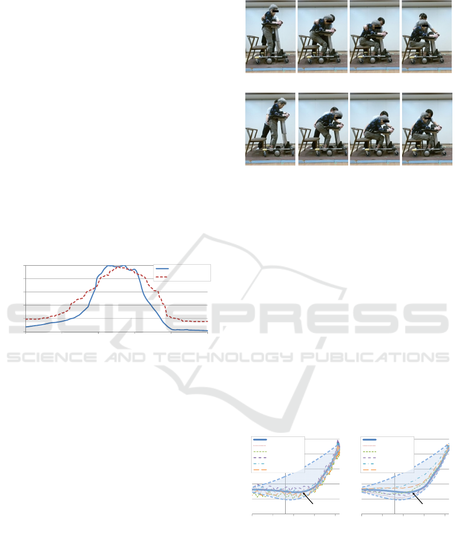
5.2 Experiments with Our Prototype
We implemented our proposed idea to the prototype
(Fig. 1) and conducted a practical experiment with it.
To confirm the efficiency of our sitting assistance, we
tested three cases.
Case1: Using only position control, without our
proposed idea.
Case2: Using our proposed idea.
We used ten subjects and each subject attempted
all three cases, five times each. Subjects were elderly
whose care level are 1 or 2. As seen in Fig. 11, our
prototype succeeds to assist the sitting motion
according to the intended motion of the subject. In
case1, the subject clings our robot during sitting
motion. On the other hand, in case 2, our robot
follows the patient’s movement to backward direction
and the subject can incline her trunk.
(a) Without proposed controller (Case1)
(b) With proposed controller (Case2)
Figure 11: Sitting motion with our assistive walker (Subject
A). The therapist stands near the subject for safety reason
and he does not assist the subject.
Fig. 12 shows the position of position P during
sitting motion. In case 1, the subject's position fits the
reference trajectory and this means our robot does not
allow the patient to move freely as intended. All
subjects has large upset because the robot applies
assistance force for fitting the reference trajectory
accurately.
On the other hand, in case 2, the subject's position
does not fit the reference trajectory but is within the
investigated tolerance range. This mean our robot
evaluates that the patient's motion fulfills both the
stability, muscle and landing conditions, and accepts
the body motion of the patient even though it does not
fit the reference pathway. As the result, the robot does
not apply any unnecessary assistive force and
succeeds in allowing the subject to use intended
sitting motion.
(a) case1
without proposed method
(b) case 2
with proposed method
Figure 12: The position of P (defined as Fig. 6(b)) during
sitting motion. Without our proposed idea (a), the position
of COG does not fit the reference and our robot tries to fit
it. Therefore, there are large upsets. In contrast with case1,
with proposed idea (b), its position moves within the
tolerance range and our robot allows the patient to move
his/her intended motion.
0
20
40
60
80
100
0 20406080100
Muscle Activity ]%]
Movement Patten [%]
EMG
Estimated Value
0.5
0.6
0.7
0.8
0.9
1
-0.08 -0.03 0.02 0.07 0.12
Y Position [m]
X Position [m]
Reference Tracks
Subject A
Subject B
Subject C
Subject D
Subject E
Tolerance Range
0.5
0.6
0.7
0.8
0.9
1
-0.08 -0.03 0.02 0.07 0.12
Y Position [m]
X Position [m]
Reference Tracks
Subject A
Subject B
Subject C
Subject D
Subject E
Tolerance Range
Sitting Assistance that Considers User Posture Tolerance
495

6 CONCLUSIONS
This paper proposes a novel sitting assistance device,
which allows patients to move through intended
movement. To realize this, we investigated the
motion tolerance of the sitting posture, which fulfills
both body balance and muscle force condi-tions.
Furthermore, we proposed a novel assistance control,
which maintains body stability whilst using intended
body motion of its user during sitting.
ACKNOWLEDGEMENTS
This work is supported in part by a Grant-in-Aid for
Scientific Research C (16K01580) from the Japan
Society for the Promotion of Science and the
Matching Planner Program (VP29117940231) from
Japan Science and Technology Agency, JST.
This study received a generous support on the
nursing sitting assistance way from Prof. Tsuyoshi
Uematsu, Mr. Yoichi Kondo (physical therapist) and
staffs on Kunitachi Nursing Station, Tokyo, Japan.
And also we received a kind support on experimental
procedure with our prototype from Mr. Kazuyuki
Hareyama (occupational therapist) and staffs on
Sankei Building Well Care Co., Ltd., Tokyo, Japan.
REFERENCES
N. B. Alexander, A. B. Schultz, and D. N. Warwick, 1991.
Rising From a Chair: Effects of Age and Functional
Ability on Performance Biomechanics, In J. of
Geometry: MEDICAL SCIENCES, vol. 46, no. 3, pp.
M91–98.
M. A. Hughes, M. L. Schenkman, 1996. Chair rise strategy
in the functionally impaired elderly, J. of
Rehabilitation Research and Development, vol. 33, no.
4, pp. 409–412.
Cabinet Office, Government of Japan, 2016. KOUREISHA
HAKUSHO (The whitepaper on the aged society),
ISBN: 4865790519, pp.25, (in Japanese).
M. Hirvensalo, T. Rantanen and E. Heikkinen, 2000.
Mobility difficulties and physical activity as predictors
of morality and loss of independence in the community-
living older population. In J. of the American Geriatric
Society, Vol.48, pp.493-498.
K. Nagai, I. Nakanishi and H. Hanabusa, 2003. Assistance
of self-transfer of patients using a power-assisting
device. In Proc. of the IEEE Int. Conf. on Robotics and
Automation, pp.4008-4015.
A. Funakubo, H. Tanishiro and Y. Fukui, 2001. Power
Assist System for Transfer Aid. In J. of the Society of
Instrument and Control Engineers, Vol.40, No.5,
pp.391-395.
Y. Ehara and S. Yamamoto, 1996. Analysis of Standing up
motion, Ishiyaku Pub. Inc, pp.65-73.
J. Yoneda, 1998. Study of Difficulties in Sitting and
Standing in the Elderly for Fall Prevention, In J. of
Yamaguchi Medical Association, Vol.47, No.3, pp.47-
59, 1998.
D. Chugo, T. Yamada, S. Muramatsu, Y. Sakaida, S.
Yokota and H. Hashimoto, 2014. A Standing
Assistance based on a Load Estimation considering
with a Muscle Arrangements at the Human Leg, In
Proc. of IEEE Int. Conf. on Robotics and Biomimetics,
pp. 1517–1522.
D. Chugo, S. Kawazoe, S. Yokota, H. Hashimoto, T.
Katayama, Y. Mizuta and K. Atsushi, 2017. Pattern
Based Standing Assistance Adapted to Individual
Subjects on a Robotic Walker, In Proc. of 26th IEEE
Int. Symp. on Robot and Human Interactive
Communication, pp.1216-1221.
E. Maki, P. J. Holliday, and A. K. Topper, 1991. Fear of
falling and postural performance in the elderly, In J.
Gerontology, vol. 46, no. 4, pp. 123–131.
S. Nuzik, R. Lamb, A. Vansant, and S. Hirt, 1986. Sit-to-
Stand Movement Pattern, A kinematic Study, In
Physical Therapy, vol. 66, no. 11, pp. 1708–1713.
V. Dubost, O. Beauchet, P. Manckoundia, 2005. Decreased
trunk angular displacement during sitting down: an
early feature of aging, In Physical Therapy, Vol.85,
No.5, pp.404-412.
M. Yokota, S. Kawazoe, D. Chugo, S. Yokota, H.
Hashimoto, T. Katayama, Y. Mizuta and K. Atsushi,
2019. Standing Assistance Control considering with
Posture Tolerance of its User, In Proc. of 2019
IEEE/SICE Int. Symp. on System Integration
, pp.543-
547.
Y. Yamamoto and N. Kado, 2015. Analysis of the sitting-
down movement, In J. Kansai Phys. Ther., Vol.15,
pp.13-16, 2015.
Opensim documentation gait 2392 and 2354 models (2018),
Available at Apr., 2019. In https://simtk-
confluence.stanford.edu/display/OpenSim/Gait+2392
+and+2354+Models
H. Okada, M. Ae, N. Fujii and Y. Morioka, 1996. Body
Segment Inertia Properties of Japanese Elderly, In
Biomechanisms, No.13, pp.125-139.
K. Kamiya, 2005. Development and evaluation of life
support technology in nursing, In Proc. of 7th RACE
Symp., Research into Intelligent Artifacts for the
Generalization of Engineering, The University of
Tokyo, pp.116-121.
ICINCO 2019 - 16th International Conference on Informatics in Control, Automation and Robotics
496
