
Improved ADRC Controller based on Model Information and Special
Filter Parameter Methods
Ze Yang
1, a, *
, Baoqing Yang
1, b
and Jie Ma
1, c
1
Harbin Institute of Technology, School of Aerospace, Control and Simulation Center, China
Keywords: ADRC, model information, Bessel filter, total disturbance, linear extended state observer (LESO).
Abstract: In the LADRC controller, the former proposes a parameter adjustment method based on bandwidth design,
but the effect still has room for improvement. This article will improve the effects of the controller in two
ways. First, the known model information of the controlled object is introduced into the controller design to
reduce the observer's interference observation load. On the other hand, the filtering methods of Bessel,
Butterworth and Chebyshev are used to design the equivalent design of the extended state observer
parameters, thereby increasing the overall performance of the controller by approximately 60%.
1 INTRODUCTION
The ADRC controller consisting of tracking
differentiator (TD), extended state observer (ESO)
and nonlinear state error feedback control law
(NLSEF) (Jingqing Han, 2009). Among them, ESO
is the core of the controller.
ESO is based on the state observer concept,
which expands various known disturbances or
unknown disturbances that can affect the output of
the system into new state variables that are easily
observed. In theory, there is no need to rely on the
exact mathematical model of the controlled object.
Any second-order victim system and its LESO
can be described as (Jingqing Han, 2007) the
Equation (1):
Among them,
12
,
x
x
are internal states,
y
is
output for the system.
12
(, )
f
xx
is acceleration
acting on the open loop system. And think of the
12
(, )
f
xx
as an extended state, recorded as
3
x
(Jingqing Han, 2007). And record
3
x
as
()t
.According to the existing theory, the above formula
is designed as a linear extended state observer.
Through the observer of the above structure, the
controlled object is compensated as
2
00
() /Gs b s
.
The parameters
123
,,zzz
in (3) is the observation of
the system state
123
,,
x
xx
,
1
e
is the error signal of the
observed value
1
z
.
0
b
is the controller gain, the
selection of this parameter is determined by the
equivalent series integration form of the controlled
object (QIN Chang-mao, QI Nai-ming, ZHU Kai,
2010). If the three parameters
01 02 03
,,
are
selected reasonably, LESO can accurately observe
the system state variables.
The parameter adjustment method of ESO is not
perfect, and it is difficult to implement under
nonlinear conditions, including neural network
algorithm (YIN Jin-song, WANG Rong-line, GAO
Qiang, ZHANG wei, 2019), particle swarm
optimization algorithm (Wang Boyu, 2018) and so
on.In the traditional LESO parameter tuning, there is
a more widely used method called pole placement
method (GAO Zhiqiang, 2003). Through laplace
transform on (2), and after constant transformation
the following results can be obtained.
122 120 111120112302103031
,(,),, , (), (), ()
x
xx fxx buy xe z yz z yzz z yz buz yz
(1)
222
2
0010030
12 3
32 32 32
01 02 03 01 02 03 01 02 03
() () ()
,,
ssy bu ssy bu sy bu
zy zsys z
sss sss sss
(2)
Yang, Z., Yang, B. and Ma, J.
Improved ADRC Controller based on Model Information and Special Filter Parameter Methods.
DOI: 10.5220/0008387603170322
In Proceedings of 5th International Conference on Vehicle, Mechanical and Electrical Engineering (ICVMEE 2019), pages 317-322
ISBN: 978-989-758-412-1
Copyright
c
2020 by SCITEPRESS – Science and Technology Publications, Lda. All rights reserved
317
TD
NLSEF
ESO
G(s)
_
_
_
u
y
Figure 1. Second-order ADRC controller structure.
32
303 010203
() / /( )Gs z f s s s
(3)
In the Equation (2),
2
0
f
sy bu
is the total
disturbance. So we can get the transfer function
()Gs
from
f
to
3
z
:
Through the transfer function relationship
between
f
and
3
z
, we can design the ESO's
observation performance of the total disturbance to
be equivalent to a low-pass filter of the form. The
traditional pole placement method or bandwidth
method is to arrange the poles of the characteristic
equations in the same position. The classic method is
as follows,
23
01 02 03
3, 3,
qqq
(GAO
Zhiqiang, 2003). In the equation,
q
is the
bandwidth configuration requirement of the
observer.
2 LESO BASED ON MODEL
INFORMATION AND FILTER
METHOD
The content of this section is mainly based on the
previous text. Because the traditional ESO does not
need to rely on the precise information of the
controlled object in theory, it makes it have certain
performance limitations in the process of use. The
combination of ESO and model information can
further reduce the observation burden and improve
the overall performance of the controller (Yao
Xiaoyan, 2018). As mentioned earlier, the
parametric design of the observer can be equivalent
to a specific form of low-pass filter parameter
design, so we can introduce some better filter
methods with better performance than the traditional
pole placement method.
We can design a similar LESO observer equation
through such a system state equation.
Similarly, the system model compensated by the
above observer is changed from
2
0
/bs
to
2
012
/( )bsasa
.
Obviously, the system model of the improved
compensation is closer to the ordinary second-order
controlled object in our actual modeling. We can
apply more known parameters to the controller, so
that the total disturbance observation can be
reduced. Reduce the burden on the observer and
avoid the problem of saturation of the system.
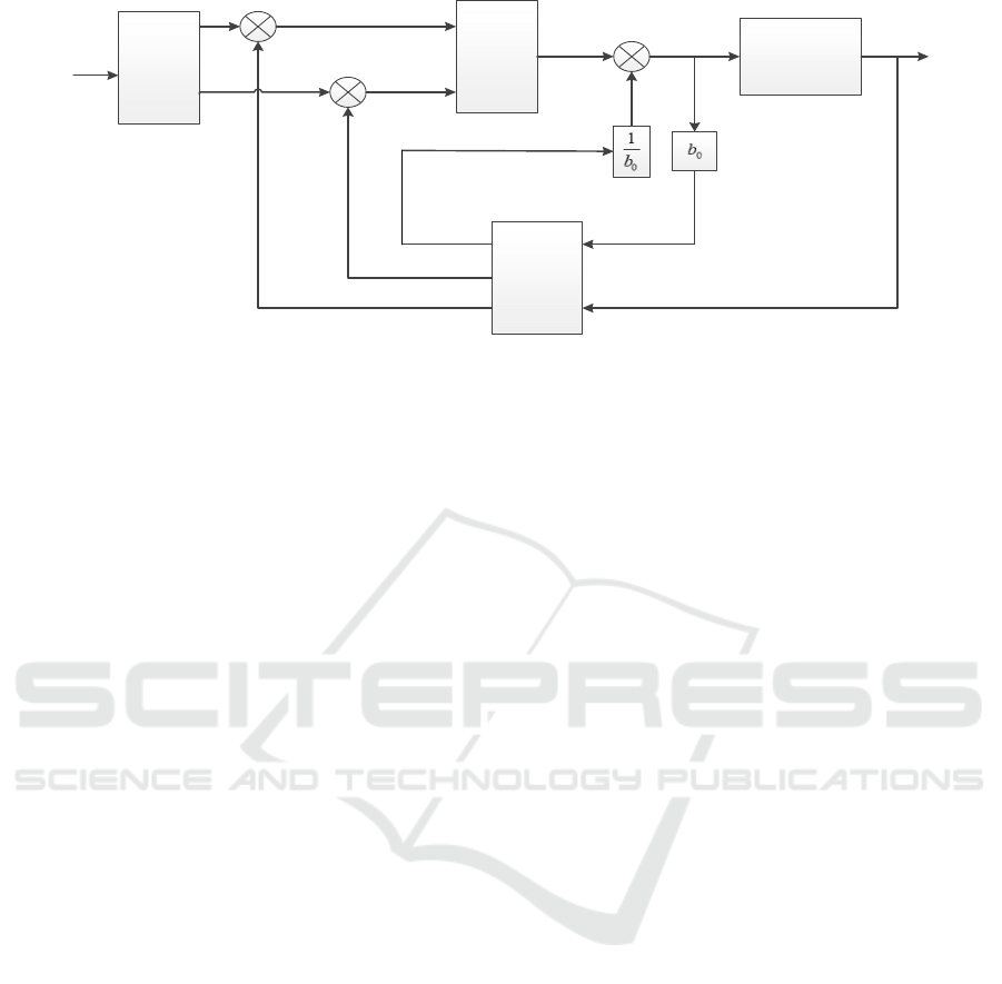
The image is a simple second-order controlled
object to perturb the signal, using two ESOs to
compare the results of the total disturbance signal
observation. From the image, we can clearly see that
the improved ESO disturbance observations are
much smaller than the ESO of the traditional
structure, leaving a lot of room for the performance
improvement of the controller.
ICVMEE 2019 - 5th International Conference on Vehicle, Mechanical and Electrical Engineering
318
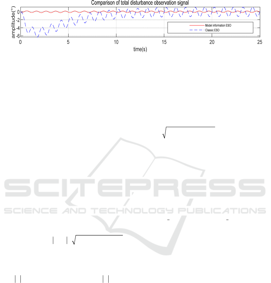
Figure 2. Comparison of disturbance observations between traditional ESO and improved ESO.
11 1 2 01 12 3 02 1 0 12213 03 1
,(), () ,()ezyzz yzz z yz buazazz yz
(4)
2.1 Introducing Four Filter Methods to
Improve LESO Parameter Tuning
Method
The Bessel filter is a linear filter with a maximum
flat linear phase response. The transfer function of
the Bessel filter is
() (0)/ ()
nnn
Ts B Bs
,where
()
n
Bs
is Bessel polynomial, which can be obtained
by a recursion formula,
01
1, 1BBs
, and
n
B
can
be written as
2
12
(2 1)
nnn
BnBsB
.
According to the pole configuration form we
need, we choose the third-order Bessel low-pass
filter. Its transfer function is in the Equation (5):
Therefore, according to the transfer function
structure parameter comparison, the parameter
formula of LESO can be obtained,
01
=6
q
,
2
02
=15
q
,
3
03
=15
q
.
The amplitude-frequency characteristic of the
Chebyshev filter is
22
(=1/(1+ (/))
nq
QT
)
,
q
is the cutoff frequency,
is passband ripple
factor, and n is filter order.
()
n
T
is Chebyshev
polynomial, can be written as
1
cos( cos ( )) n
,
when
1
,and
1
cosh( cosh ( ))n
,when
1
.
Chebyshev polynomial is selected as 6 times.
The specific form is
64 2
6
() 32 -48 18 1T
Take
max
as 1, then bring it into amplitude-
frequency characteristic equation, Solve the filter
transfer function by writing a Matlab program.
So we can get the parameter expression of the
filter in the Equation (6):
Therefore, according to the transfer function
structure parameter comparison, the parameter
formula of LESO can be obtained,
01
0.98834
q
,
2
02
1.2384
q
,
3
03
0.49131
q
.
The amplitude-frequency characteristic
expression of the Butterworth filter is
2
() 1/(1 / )
N
q
Qjj
.
Under ideal conditions, meet the condition
(/ )1
q
in the passband, and so
2
(/ )
N
q
decreasing gradually and gradually approaching 0 as
N increases. Its amplitude squared function can be
decomposed into 2N poles, and uniformly
symmetrically distributed over the circumference of
radius
q
. We use a third-order Butterworth filter,
considering the stability requirements of the system,
so we only select the three poles of the left half
plane. They can be written as
22
33
111
,,
jj
pq p qpq
ses se
So after a simple transformation and comparison
with (6), the relationship between the observer
parameters and the set bandwidth can be obtained,
01
2
q
,
2
02
2
q
,
3
03 q
.
3 SIMULATION VERIFICATION
In this chapter, we model and simulate the above
theory and method to verify the theoretical
feasibility and effect, and combine the turntable
motor to simulate and verify the performance after
applying the new method.
We changed the LESO used in the simulation to
an improved LESO which based on model
information, and compared several of the above
parameter adjustment methods to verify the
performance of the observer under different filter
design methods.
Improved ADRC Controller based on Model Information and Special Filter Parameter Methods
319
32 33 2 2 3
() 15/( 6 15 15) () (15 )/( 6 15 15 )
qqqq
Hs s s s Qs s s s
(5)
33 2 2 3
( ) 0.49131 / ( 0.98834 1.2384 0.49131 )
qqqq
Qs s s s
(6)
Figure 3. Comparison of classical bandwidth and Chebyshev filter ESO observation error.
Among the above simulation images, since these
parameters tuning methods all depend on the given
bandwidth parameters, we set it as 800 to facilitate
the performance comparison of the observer.
123
,,eee
are the observation errors of
12
,
x
x
and
3
x
respectively.
The observation value of
3
e
is the error signal of the
total disturbance, which is an important indicator for
measuring the performance of the observer. It can be
seen that under the method of using the Chebyshev
filter, the observation error value of the total
disturbance signal has reduced compared with the
conventional bandwidth method. And these four
LESO parameters are set in same bandwidth
condition compared with each other. The decrease of
the observation error value, which can help to
improve system performance, and which result will
be verified in subsequent simulations. We can see
from the observation error signal curve that the
LESO with Bessel filter equivalent parameter design
has the highest observation accuracy, and its error
value reduced by about 50%, compared with the
classical bandwidth method and other filter
equivalent parameter design methods.
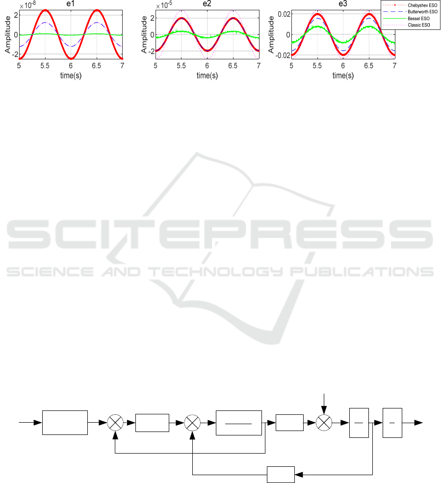
At present, most of the turntable devices use
permanent magnet synchronous motors as the
actuator. Therefore, in order to verify the application
effect of the above theory, we use permanent magnet
synchronous motor as the controlled object. Its
system block diagram is shown in Fig 4.
We take
e
as 0.00391909482,
m
as 0.98095377,
K
as 89.55074799.
In the simulation verification test, the parameters
of the previous turntable are selected as the basic
conditions, and the system is subjected to
disturbance signals and dead zone characteristics.
Dead zone characteristics are -10 N•m to +10 N•m.
Rate perturbation and position perturbation are 50%
of the input signal amplitude and frequency is
1rad/s.
We use the most common types of signals as
inputs to simulate and verify the performance of the
controller, including sinusoidal signals, step signals,
and ramp signals.
v
K
in
V
p
s
K
1
Ls R
T
K
i
e
T
f
T
1
J
s
1
s
e
K
Figure 4. Turntable motor equivalent transfer function block diagram.
The equivalent transfer function can be written as:
ICVMEE 2019 - 5th International Conference on Vehicle, Mechanical and Electrical Engineering
320
2
() ()/ () (1/ )( / )/( / ( ) / 1)
vps e Te ps Te
G s s R s s k k k LJs k k k r Js k k
(7)
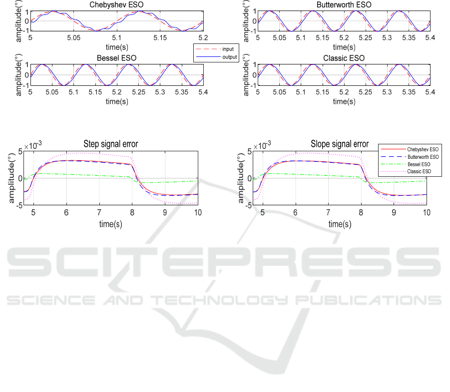
Figure 5. Comparison of 10Hz sinusoidal signal output under four methods.
Figure 6. Comparison of output error under four methods.
We used a 10Hz sinusoidal signal as input to test
the dynamic tracking performance of the system
using different design methods. The standard phase
error should not exceed 10ms, and the amplitude
error should not exceed 10% of the input signal.
Then, we can see the difference between the input
and output amplitudes under the method of using the
Chebyshev filter , its amplitude error is 0.138°, and
its anti-disturbance capability is very bad, and the
output signal has experienced drastic fluctuations,
which cannot meet the indicator requirements. And
the difference between the input and output
amplitudes under the method of using the
Butterworth filter is 0.035° and the phase difference
is 3.491 ms. the difference between the input and
output amplitudes under the method of using the
Bessel filter is 0.033° and the phase difference is
2.405 ms.
Combined with the above results, we can get the
conclusion, the Chebyshev filter method cannot
make the system track the 10Hz sinusoidal signal,
the Bessel filter method is the best, the Butterworth
filter method is second, and the classical bandwidth
method is third.
In the above step response test, we added a
disturbance factor that can simulate the actual
situation of the turntable motor system, such as the
dead zone characteristics in the motor and the low
frequency disturbance at the position output and
speed output. Dead zone characteristics are -10 N•m
to +10 N•m. Rate perturbation and position
perturbation are 50% of the input signal amplitude
and frequency is 1rad/s. It can be clearly seen that
when the Bessel filter method is used, the steady-
state error of the system is the smallest, the
Butterworth filter method is second, the Chebyshev
filter method is third, and the classic bandwidth
method is the largestIf the accuracy of the system is
high, we should use the Bessel filter method for
LESO design. Similarly, we use the ramp signal as
an input to test the system's minimum angular
velocity and detect if the error meets the accuracy
requirements. The ramp signal slope is 0.002°/s.
From the results, the best is still Bessel method, the
second is the Chebyshev, Butterworth. The classic
bandwidth method has the largest steady-state error.
4 CONCLUSION
We propose the Bessel filter method, the
Butterworth filter method, and the Chebyshev filter
method. In the simulation results, we can find that
among the above three design methods, the Bessel
Improved ADRC Controller based on Model Information and Special Filter Parameter Methods
321

filter method shows good controller performance
under various input signals. Among them, the Bessel
filter design method has the best performance. In the
future, in the design of the servo system controller,
we can use the information of the controlled object
model and several filter equivalent parameter design
methods proposed in this paper to meet the
increasing precision requirements. In the servo
control system, if there is a high demand for
accuracy and anti-disturbance capability, the
parameter design method mentioned in this paper
can be applied.
REFERENCES
GAO Zhiqiang. Scaling and bandwidth-parameterization
controller-tuning [C] //Proceedings of the 2003
American Conference. Denver: IEEE, 2003, 6: 4989-
4996.
Guozhang, Gao,Shipeng Zhang,Lan Gao. Research on
excitation control system of marine brushless
generator base on ADRC [J]. SHIP SCIENCE AND
TECHNOLOGY, 2018, 40(21):116-120.
Jingqing Han. Active Disturbance Rejection Control
Technology - Control Technique for Estimating
Compensation Uncertain Factors [M]. National
Defense Industry Press. 2009.
Jingqing Han. Active Disturbance Rejection Control
Technology [J]. Frontier Science, 2007(01):24-31.
QIN Chang-mao, QI Nai-ming, ZHU Kai. Active
disturbance rejection attitude control design for
hypersonic vehicle [J]. Systems Engineering and
Electronics, 2010, 33 (7): 1607-1610.
Wang Boyu. Intelligent Algorithm - Based Optimization
Design and Application of Active Disturbance
Rejection Controller [D]. Northeast Petroleum
University, 2018.
Yao Xiaoyan. Research on design method of active
disturbance rejection controller for electric load
simulator [D]. Harbin Institute of Technology, 2018.
ICVMEE 2019 - 5th International Conference on Vehicle, Mechanical and Electrical Engineering
322
