
Research on Sensorless Fuzzy PID Control of BDCM based on
Improved State Observer
Hanghang Qu
1, a
, Jie Zeng
1, b
, Ran Sheng
1
and Yongwei Guo
1
1
School of Electrical Information, Dalian Jiaotong University, Dalian, Liaoning , People’s Republic of China
Keywords: BLDCM, state observer, line back-EMF, fuzzy PID.
Abstract: Relative to traditional methods of back-EMF zero crossing points (ZCPs) delay detect, a new method to
detect the rotor position of BLDCM is proposed by constructing a state observer to estimate line back-EMF
based on line voltage and line current in this paper.And improve the observer, the linear error function is
added to the original nonlinear error feedback coefficient of the observer. The combination of the two
functions helps accelerate the convergence of the observer and improve the stability of the observer.In order
to make its rotate speed more stable, the fuzzy PID is used to replace the traditional PID for the outer ring of
the rotate speed.Finally, the simulation results show that this method can accurately estimate the position
information of the rotor. With the help of the fuzzy PID control method, the precise control of BLDCM can
be realized in a wide speed range.
1 INTRODUCTION
Compared with DC motor, BLDCM is widely used
in various fields due to its strong anti-interference
ability, high operating efficiency and excellent speed
control performance. The traditional control method
of BLDCM usually uses position sensor to collect
rotor position information to controll
commutation.However, the increase of position
sensor makes the internal circuit connection of the
whole system more complex, the anti-interference
becomes worse and the size of the whole system is
increased. Moreover, in some special working
environments with high temperature and humidity,
the precision and reliability of sensors are required
to be higher, which additionally increases the
difficulty of sensor technology. Therefore,
sensorless control technology of BLDCM has
become an important research direction.
The first problem to be solved by sensorless
control is rotor position detection. A method to
obtain rotor position by back-EMF Integration and
phase compensation is described in (
Shengjin L.et al.,
2008
), but this method needs to obtain the phase
offset angle of the back-EMF detection circuit at
different rotational speeds, which requires high
hardware memory; In (
Umesh Kumar S.et al, 2017),
Umesh Kumar proposed a new position-free sensor
six-switch variable structure input permanent
magnet brushless DC motor back EMF zero
differential detection scheme. This technique is
based on the comparison of the back electromotive
force and the detection of points crossing each other
in the back electromotive force waveform to obtain a
commutation point; In (
Shuai Y.et al., 2016), the back-
EMF is calculated by calculating the back
electromotive force by the sampling line voltage,
which is easy to implement in hardware, and the
software operation is simple, and the control CPU
consumption is low; In (
Tae-Sung K.et al., 2006), a
state observer is used to detect the back-EMF of a
brushless DC motor to estimate the rotor position,
and the control effect is good.
Observer gain is a key factor affecting the fast
convergence and stability of the observer. Inspired
by literature (
Shuai Y.et al., 2016; Tae-Sung K.et al.,
2006; Chang cheng Y, 2017
), based on the relationship
between the line back-EMF and the commutation
point, this paper constructs the line back-EMF state
observer to estimate the rotor position information
online and added a linear error function, accelerates
the convergence of the observer and improves the
stability of the observer. In order to further make the
motor speed more stable, fuzzy PID is used to
correct the speed. The simulation results shows that
the method can accurately predict the rotor position
to achieve the purpose of sensorless control and
416
Qu, H., Zeng, J., Sheng, R. and Guo, Y.
Research on Sensorless Fuzzy PID Control of BDCM based on Improved State Observer.
DOI: 10.5220/0008868704160420
In Proceedings of 5th International Conference on Vehicle, Mechanical and Electrical Engineering (ICVMEE 2019), pages 416-420
ISBN: 978-989-758-412-1
Copyright
c
2020 by SCITEPRESS – Science and Technology Publications, Lda. All rights reserved

achieve fast response and smooth operation of the
motor.
2 MATHEMATICAL MODEL OF
BLDC MOTOR
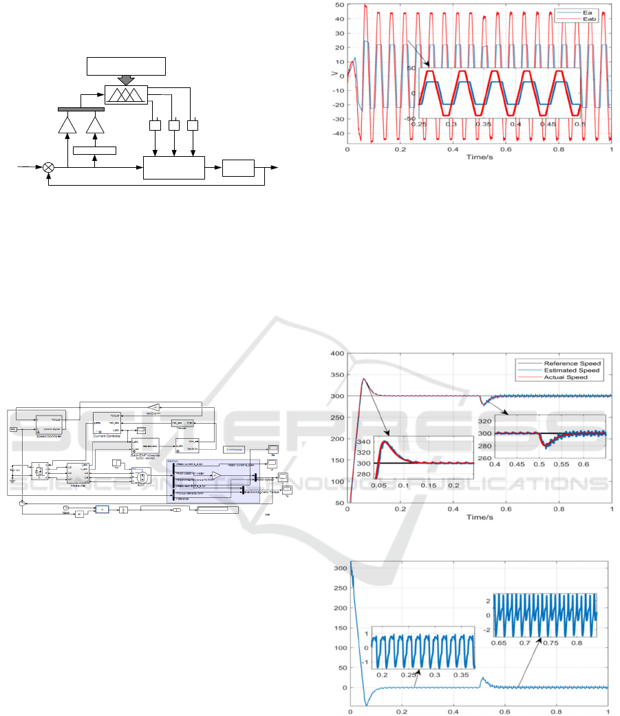
The control circuit topology of BLDC motor is
shown in figure 1. Three-phase winding of motor is
star connected. To facilitate the analysis, we assume
that the three-phase winding of BLDCM are
symmetrically distributed, the internal hysteresis
losses and eddy current losses are neglected, and the
power switches are ideal switches. Then the stator
winding voltage equation of BLDC motor can be
expressed as:
c
b
a
c
b
a
c
b
a
c
b
a
e
e
e
i
i
i
dt
d
LMM
MLM
MML
i
i
i
R
R
R
u
u
u
00
00
00
(1)
Where, ua, ub and uc are the three-phase stator
winding terminal voltage, ia , ib and ic are the
currents of phase winding, ea, eb and ec are back-
EMF of each phase winding, R is resistance of each
phase winding, L is self-inductance of each phase
winding, M is mutual inductance of each phase
winding.
R
R
R
L
L
L
e
a
e
b
e
c
+
-
+
+
-
-
n
+
_
V
dc
T
1
T
2
T
6
T
4
T
3
T
5
ia
ib
ic
BLDCM
Figure 1. The control circuit topology of BLDC motor.
The motor is in normal operation, the
electromagnetic power of the motor is the sum of
three-phase winding electromagnetic power,
ignoring the mechanical and other losses of the
motor itself, the electromagnetic power will be
transformed into the rotating mechanical power,
expressed as:
meaaaaaae
TieieieP
(2)
Where, Te is the electromagnetic torque and ωm
is the mechanical angular velocity.
3 ROTOR POSITION ESTIMATE
BASED ON LINE BACK-EMF
3.1 Improved State Observer based on
Line Back-EMF
Because the mutual inductance between three-phase
windings is very small, it can be neglected (
Surya
Susan A&Asha Elizabeth D, 2019).By subtracting
formula (1), the line current, line voltage and line-
back-EMF equations (3) can be obtained.
(3)
As can be seen from the above formula, except
that the back-EMF is unknown, all other variables
can be measured, so the above formula is rewritten
to the equation about current (4).
ca
bc
ab
ca
bc
ab
ca
bc
ab
ca
bc
ab
e
e
e
L
u
u
u
L
i
i
i
R
R
R
L
i
i
i
11
00
00
00
1
ˆ
ˆ
ˆ
(4)
Where,
ba
ab
ab
ii
dt
di
i
ˆˆˆ
, uab, iab as the known
variable,can all be measured in practice.eab as an
unknown variable,iab and uab can be used to
construct the eab’s equation of state for observation.
In order to make the system get faster
convergence speed and improve the stability of the
estimator, a linear error function Sgmf (x) is added
based on equation (5).
)
ˆ
()
ˆ
(
)
ˆ
()
ˆ
(
0
1
ˆ
ˆ
00
1
ˆ
ˆ
2
1
iiSgmfii
iiSgmfii
k
k
u
L
e
i
LL
R
e
i
ab
ab
ab
ab
ab
(5)
Where, k1 and k2 are the nonlinear error
feedback gains of the observer, which can be
obtained by pole configuration;and "Sgmf"
represents a linear error function, denoted
Sgmf(x)=1/1+e-cx, where c is a tunable parameter
(
Surya Susan A&Asha Elizabeth D, 2019).
The improved observer differs from the
traditional observer in that it consists of a linear
error function term and a nonlinear error term
characterized by gains k1 and k2. Linear error
function help accelerate the observer error to zero
and the nonlinear error term weakens the fluctuation
ca
bc
ab
ca
bc
ab
ca
bc
ab
ca
bc
ab
e
e
e
i
i
i
dt
d
L
L
L
i
i
i
R
R
R
u
u
u
00
00
00
00
00
00
Research on Sensorless Fuzzy PID Control of BDCM based on Improved State Observer
417

of the estimated state quantity, which ensures the
robustness of the observer. The gain value is
calculated offline based on different speed and load
torque conditions and stored in a table from which
the gain value is selected based on operating
conditions.
Subtracting primitive state equation of current
from equation (5) to obtain,
)]
ˆ
()
ˆ
[(
ˆ
)]
ˆ
()
ˆ
[()
ˆ
(
1
)
ˆ
(
ˆ
2
1
abababababab
abababababababababab
iisgmfiikee
iisgmfiikee
L
ii
L
R
ii
(6)
According to the synovial control theory,
0
ˆ
iiS
is defined as the synovial surface. To
prove the stability of the observer in the above
theory, the Lyapunov stability function is defined as
2/)
ˆ
(
2
iiV
.The condition for stability is
V
≤0
for V>0.The calculation shows, the estimation error
is made to converge faster with the proper choice of
the observer gains satisfying the conditions k1>0
and k2/k1<0 (
Surya Susan A&Asha Elizabeth D, 2019
).
3.2 Estimation of Motor Rotor Position
The ideal back-EMF of brushless DC motor
distributes in a trapezoidal shape with 120 degrees
flat top width. Above, the relationship between line
voltage, line current and line back-EMF is deduced,
and the state equation is constructed to calculate line
back-EMF. The relationship between line back-EMF
and back-EM is given below, as shown in Figure 2.
π
2π
π/2
3π/2
e
ab
e
bc
e
ca
e
a
e
b
E
‐E
2E
‐2E
0
Figure 2. The relationship between the line back-EMF and
the back-EMF.
Taking ea as an example, when ea is at π/ 6, ea
value is the largest and electromagnetic torque is the
largest, which is the commutation point.As can be
seen from figure 3 above, when ea is at π/6, the line
back-EMF eca = 0, so it can be concluded that the
zero crossing point of line back-EMF is the best
commutation point for brushless DC motor rotor.
Similarly, eb and ec are similar. The method can
effectively avoid the error caused by the traditional
method delay of 30 degrees. At the same time, the
line back-EMF is estimated by line voltage and line
current, it is also applicable in the case of low speed
motor. According to the previous formula (6), Take
eab as an example, the design of line back-EMF
state observer in the Simulink model is shown in
figure 4.
1/L
1/L
+
-
+
-
1/S
R/L
1/S
K1
K2
u
ab
i
ab
e
ab
+
-
Sigmf
Function
+
+
Figure 3. The relationship between the line back-EMF and
the back-EMF.
When the motor works normally, the line back-
EMF is proportional to the constant of back-EMF
and the speed of motor (
Tang L, 2014). At any time,
the maximum of the line-back-EMF is twice the
maximum of the back-EMF.
pkE
mee
ˆ
2/
ˆ
max
(7)
Where, Emax is the maximum value estimated
from line back-EMF, ke is the constant of back-
EMF.
e
ˆ
is estimated value of electric angular
velocity of motor. p is the polar logarithm of the
motor.
The position information of the motor's rotor is
the integral of its electric angle, which is expressed
as follows.
0
ˆ
ˆ
dt
e
(8)
θ0 is the initial angle of the rotor of the motor,
which is usually taken as 0.The rotor position
information is obtained according to the estimated
value of the line back-EMF, and then the
commutation signal is got to drive the three-phase
full-bridge switch tube, and the position sensorless
control of the brushless DC motor is realized.
4 DESIGN OF FUZZY PID
CONTROLLER
In order to ensure the smooth operation of motor
speed and achieve accurate speed control. In this
paper, the parameters of conventional PID controller
are intelligently adjusted by using velocity deviation
ICVMEE 2019 - 5th International Conference on Vehicle, Mechanical and Electrical Engineering
418
e and deviation change rate ec as input of the
controller.Figure 4 illustrates the block diagram of
an fuzzy PID controller.
-
+
n
*
e ec
Differentiator
kp
0
ki
0
kd
0
XXX
Fuzzy Control Rules
Conventional
PID
Object
n
Figure 4. The block diagram of an adaptive fuzzy PID
controller.
5 DESIGN OF FUZZY PID
CONTROLLER
According to the previous analysis, in order to verify
the effectiveness of the algorithm, a simulation
platform for sensorless control of BLDCM is built
by using MATLAB/Simulink, as shown in figure 5.
c
Figure 5. Sensorless Control Model of Brushless DC
Motor.
The parameters of the motor are set as follows:
V=300Vdc, stator resistance Rs=0.2, stator
inductance Ls=8.5e-3H, moment of inertia
J=0.089kg/m2, Back-EMF coefficient
ke=0.175V/rad/s, pole logarithm p=4, Observer gain
k1, k2 and linear error function coefficient c select
the best value.
The motor is accelerated with a speed reference
of 300 rpm and give a full load torque at 0.5 s.
Figure 6 is a waveform diagram of the line back-
EMF and back-EMF. By comparison, the estimated
line back-EMF of the design used in this design is
indeed twice the back-EMF measured on the motor
side, which is consistent withthe previous analysis,
which proves the correctness of the design method.
Figure 6. Waveform comparison of line back-EMF and
back-EMF.
Figure 7 illustrates that the estimated speed
follows closely with the actual speed.This
establishes the effectiveness of the observer with
optimal gain values. Figure 8 shows the error value
of the speed estimation. When the speed is low, the
initial load is half load start, the error is less than
1.5rpm, and the load is fully loaded at 0.5 seconds,
and the error value is less than 2.5rpm.
Figure 7. Estimated and actual rotor speed.
Figure 8. The speed estimation error value.
In order to achieve precise control of speed,
eliminate overshoot, add fuzzy controller to the
improved observer control system. The simulation
results are shown in Figure 10 and Figure 11.
Research on Sensorless Fuzzy PID Control of BDCM based on Improved State Observer
419
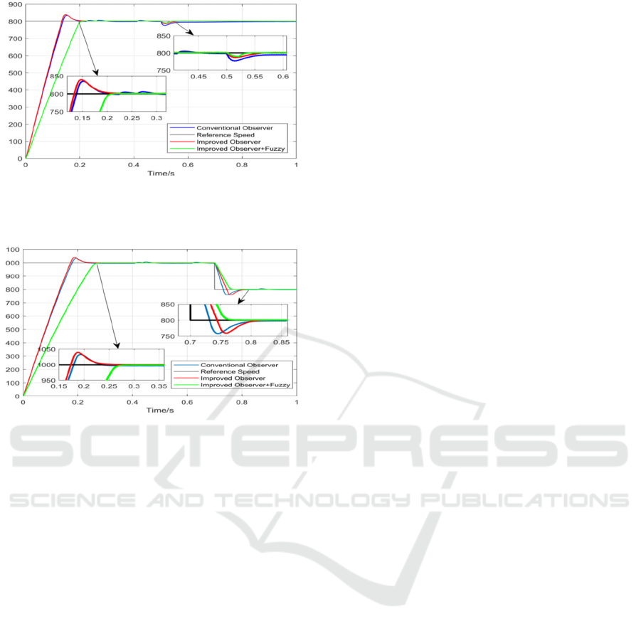
Figure 9. Contrast of Speed of different loads under
Conventional Observer, Improved Observer and added
fuzzy controller.
Figure 10. Contrast of Different Speed Motor under
Conventional Observer, Improved Observer and after
adding Fuzzy Controller.
Figure 9 shows the results of the sudden load
test. It can be seen from the figure that before the
fuzzy controller is added, the conventional observer
and the improved observer have overshoot in the
startup process. But it is seen from the simulation
results that the rotational speed waveform of the
traditional back-EMF observer is unstable at the
later stage. The load is suddenly increased at 0.5
seconds, the traditional observer speed drop value is
larger than the improved observer. After adding the
fuzzy controller, the speed overshoot disappears.
Figure 10 shows the response of different control
systems to different speeds.
6 CONCLUSION
Aiming at the defects of traditional sensorless
control based on back EMF, this paper proposes a
state observer based on line voltage and line current,
and improves the observer, adding a linear error
function to accelerate the convergence of the
observer and improve the observer stability. The
simulation experiments show that the method is
effective and has a certain promotion effect on the
operation of brushless DC motor in special
environment, which is of great significance.
ACKNOWLEDGMENT
The paper has been funded by Science Projection of
Liaoning Province Education Bureau (JDL2017039
&JDL2017040).
REFERENCES
Changcheng Y. 2017. Design of Sensorless Brushless DC
Motor Control System, Hefei Polytechnic University,
HeFei, China.
Shengjin L.et al., 2008. BLDCM control based on integral
compensation of back EMF. Micro-Special Motor, (6),
p.36-39.
Shuai Y.et al., 2016. A New Method for Determining
Rotor Position of Brushless DC Motor by Line
Voltage. Micro-Special Motor, (44), p. 37-40.
Surya Susan A&Asha Elizabeth D., 2019. Optimal Gain
Selection Strategy in Back EMF Observer for Position
Sensorless Operation of BLDC Motors. Arabian
Journal for Science and Engineering.
Tae-Sung K.et al., 2006. Unknown Input Observer for a
Novel Sensorless Drive of Brushless DC
Motors,Twenty-First Annual IEEE Applied Power
Electronics Conference and Exposition, p.679-684.
Tang L., 2014. Research and Implementation of
Sensorless Brushless DC Motor Control System,
Hunan University, Changsha, China.
Umesh Kumar S.et al., 2017. Novel Back-EMF Zero
Difference Point Detection Based Sensorless
Technique for BLDC Motor, IEEE International
Conference on Industrial Technology (ICIT), p.330-
335.
ICVMEE 2019 - 5th International Conference on Vehicle, Mechanical and Electrical Engineering
420
