
Analysis of K&C of Torsion Beam Suspension based on a Vehicle
Model
Liguang Wu
1, a
, Guang Li
1, b
and Lixin Jing
1, c
1
China CATARC(Tianjin) Automotive Engineering Research Institute Co.,Ltd, Tianjin, P.R. China
Keywords: The opening angle, Beam position, Bush installation angle, Toe angle, Height of the roll center.
Abstract: In this paper, through the flexible body of torsion beam established by HyperMesh is introduced into
ADAMS/CAR software for simulation of suspension K&C characteristics. The influences of three factors,
such as the opening angle of the beam, beam position and bush installation angle, on the K&C performance
of the suspension are obtained. The analysis shows that the opening angle and position of the beam have a
great influence on the K&C characteristics of the suspension, especially the change of toe angle and height
of the roll center, and provides a reference for the design of the torsion beam at early stages and a direction
for the suspension K&C characteristics optimization in late period.
1 INTRODUCTION
The vehicle suspension is an important component
of the vehicle in affecting the ride comfort and
handling stability (Shang Guan, etc, 2009),
especially when the vehicle passes uneven road, the
impact of suspension on the performance of the
vehicle is obvious. The torsion beam suspension is
semi-independent suspension between rigid axle
suspension and independent suspension, because the
torsion beam is elastic, both sides of the wheel have
a certain independence. Due to the small space and
low manufacturing cost, the torsion beam suspension
is widely used in various economical cars and SUV.
In severe conditions, the beam has a more stable
effect on the body roll and steering roll, equivalent
to a stabilizer bar (Liao and Su, 2015). Therefore,
taking into account the role of load transfer, a
reasonable beam opening angle and position are
required.
In this paper, based on a model, through the
flexible body of torsion beam established by
HyperMesh is introduced into ADAMS/CAR
software for simulation. The influences of three
factors, such as the opening angle of the beam, beam
position and bush installation angle, on the K&C
performance of the suspension are obtained.
2 DYNAMIC ANALYSIS OF
TORSION BEAM SUSPENSION
2.1 Torsion Beam Suspension Model
Torsion beam suspension includes two coil springs
and an integral V-section beam which welds a
variable cross-section tubular arm to form an overall
framework. The front of the trailing arm is
articulated with the body by bushings and the rear is
connected with the hub and shock absorber (Chen
and Ma, 2006). When the car passes through
different roads, torsion beam suspension transmits
force to the body through bending and torsional
deformation. The torsion beam suspension topology
is shown in Figure 1.
When the vehicle is driving, the wheels drive the
beam to swing up and down relative to the body
with the rubber bushes which are an asymmetric
rubber wedge structure with low radial stiffness and
large axial stiffness at the front of the trailing arm as
the fulcrum; The V-shaped section beams produce
torsional deformation when the deformation of the
suspension on both sides of the beam is not the
same, so it should have greater flexibility and act as
a stabilizer bar.
78
Wu, L., Li, G. and Jing, L.
Analysis of KC of Torsion Beam Suspension based on a Vehicle Model.
DOI: 10.5220/0008868900780084
In Proceedings of 5th International Conference on Vehicle, Mechanical and Electrical Engineering (ICVMEE 2019), pages 78-84
ISBN: 978-989-758-412-1
Copyright
c
2020 by SCITEPRESS – Science and Technology Publications, Lda. All rights reserved
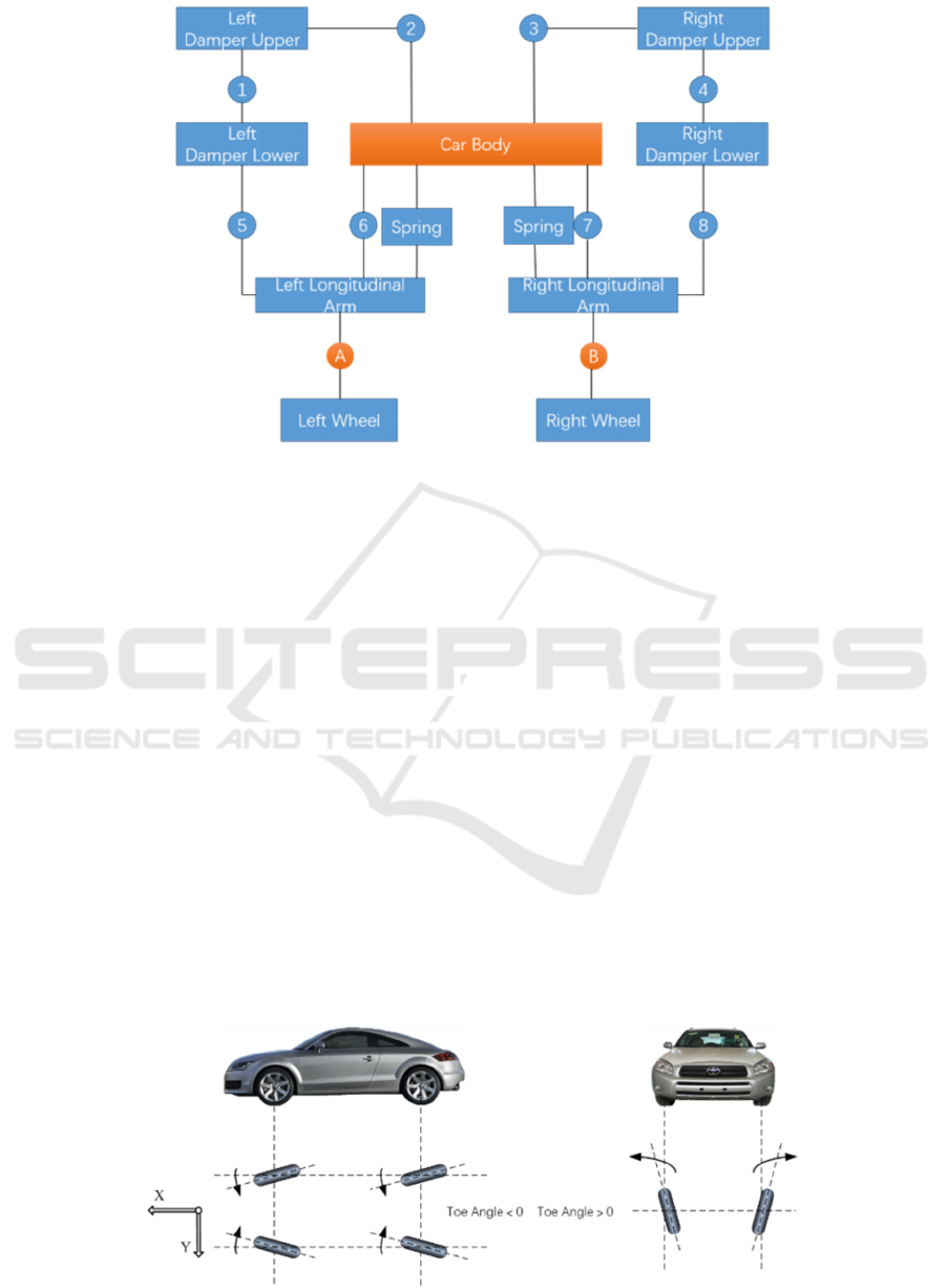
Fig 1. Torsion beam suspension topology.
2.2 Analysis of K&C Characteristics of
Torsion Beam Suspension
The kinematics of the suspension system is mainly
divided into two aspects: kinematics and elastic
kinematics (Kinematics & Compliance), Kinematics
related to comfort describes changes in wheel
alignment parameters and vertical stiffness
characteristics of the suspension during spring
deformation or wheel turning; Elastic kinematics
related to handing stability describes the changes of
wheel alignment parameters and suspension
stiffness(Sun, 2012). Operating conditions of
suspension K&C feature include Parallel wheel
jump, rolling conditions, lateral force conditions,
aligning torque conditions, longitudinal force
conditions, steering conditions. And related
parameters include toe angle change, roll stiffness
change, suspension roll center height, etc.
The toe angle is the angle between the
longitudinal center plane of the car and the line of
intersection between the center plane of the wheel
and the ground. If the front of the wheel is inclined
toward the longitudinal center plane of the car, it is a
toe angle greater than zero, conversely, less than
zero, as shown in picture 2. The toe angle is equal to
the side slip angle of the tire when viewed in the
direction of travel of the car(Chen, 1997), as shown
in picture 3, so the car has a good straight-line
driving performance and no side-slipping due to the
symmetrical arrangement of the wheels diagonally
to the longitudinal center plane. In order to reduce
the wear and rolling resistance of the tire and ensure
the straight running performance of the vehicle,
there should not be a large change in the toe angle
when wheels jump. For the rear suspension which
has a greater effect on the steady state rotation of the
vehicle compared with the front suspension. The toe
angle increases when the wheel is jumping, and the
toe-angle decreases when the wheel is lowered, what
ensures the rear axle produces understeer when the
car turns.
Fig 2. Toe angle.
Analysis of KC of Torsion Beam Suspension based on a Vehicle Model
79
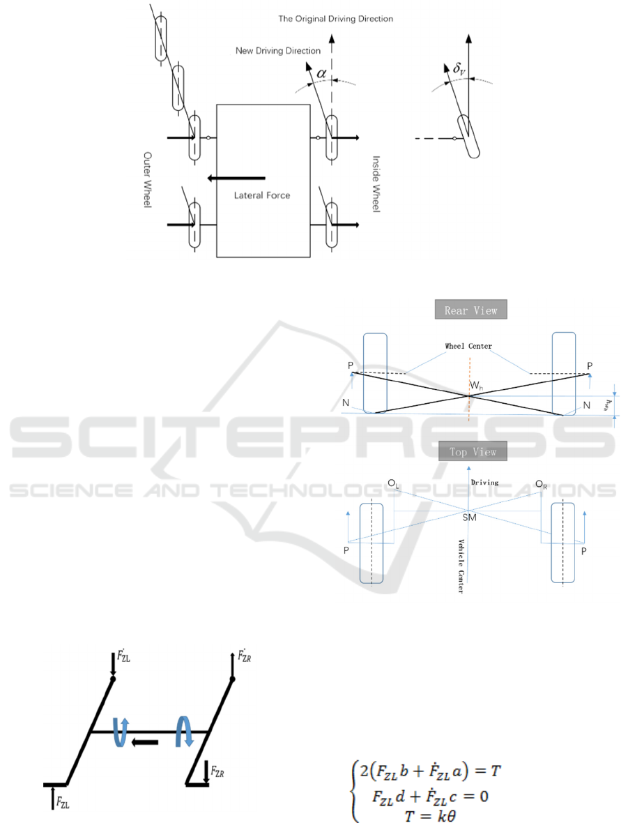
Fig 3. Toe angle in the direction of driving.
The roll center of the suspension belongs to a
point in the cross section of the car at the axle. At
this point, when the lateral force is applied to the
vehicle body, the angular displacement of the sprung
mass does not occur. Because the roll center is the
instantaneous center of rotation of the cross section
of the car at the axle. It is also called "the instant
heart"(Ma, etc, 1999). When the vehicle turns, the
load of the vehicle shifts laterally. Under the effect
of centrifugal force, the carriage roll around the roll
center, so that the body roll moment changes. The
roll moment is the sprung mass centrifugal force
multiplied by the roll center to the force vertical
distance. For the torsion beam suspension, the
torsion beam suspension is twisted when the vehicle
is running on a curve, increasing the lateral stiffness
of the suspension, reducing the body roll angle.
Plays a role in improving the stability and stability
of vehicles. The torsion force of the torsion beam is
shown in Figure 4, and the roll center is shown in
Figure 5.
Fig 4. Torsion beam force when rolling.
Fig 5. Roll center height of torsion beam Suspension.
The beam torsional moment T of torsion beam is
generated by two pairs of couples:
2
0
θ
(1)
In the formula:
a —The longitudinal distance from the torsion
beam to the body mounting point;
ICVMEE 2019 - 5th International Conference on Vehicle, Mechanical and Electrical Engineering
80
b —The longitudinal distance from the torsion
beam to the rear wheel center;
c —The rear wheel track;
d —The lateral distance from the torsion beam to
the body mounting point;
θ —The relative twist angle of the two ends of
the beam
The greater the height of the roll center, the
shorter the distance from the center of roll to the
center of mass, the smaller the roll arm and roll
moment, so that the vehicles achieve a smaller body
roll angle and lateral transfer load, what contributes
to the vehicle's transient steering performance.
However, if the roll center is too high, the wheelbase
changes too much when the body roll occurs, which
intensifies tire wear, and straight-line driving
performance of the car reduced. If the roll center is
reduced, the wheelbase changes greatly, and a
camber angle less than zero is formed, what increase
the ability to withstand lateral forces, but will reduce
the jump limit of the suspension. In short, the height
of the roll center of the suspension needs to have a
reasonable range. Generally, the height range of the
front independent suspension center is 0~120mm,
and the rear independent suspension range is
80~150mm. Rear torsion beam suspension has a
higher roll center height of 100-150mm.
Roll center height H:
H
∗
(2)
In the formula:
— the change of wheel track, — round
trip,
—track distance.
3 THE K&C SIMULATION
ANALYSIS OF TORSION BEAM
SUSPENSION
Based on a small car with a rear torsion beam
suspension, the comparison of the K&C
characteristics of the suspension is performed by
selecting different opening beam angles, beam
positions, and the bush installation angle. The main
design parameters of the rear suspension of this
sample car are shown in Table 1.
In this paper, the three-dimensional models of
different torsion beams established by CATIA
software are imported into the HyperMesh finite
element processing software, are divide grid with
attributes, and are import into ADAMS/CAR
software. Finally, a rigid-flexible coupled multi-
body dynamics model of the rear torsion beam
suspension was established and simulated of K&C.
The simulation results are compared with the test
results to verify the accuracy of the model.
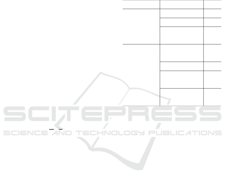
Table 1. Design Parameters.
system parameter value
Vehicle
Total mass (Kg) 1058
Wheelbase (mm) 2320
Track distance
(mm)
1450
Rear torsion
beam
suspension
Toe angle (°)
-
0.476
Camber (°) -1
Spring stiffness
(N/mm)
30.7
Beam thickness
(mm)
29
In the original model, the opening direction of
rear torsion beam is downward, Then performing a
suspension K&C comparison analysis by rotating 90
degrees, 180 degrees clockwise, turning 90 degrees
counterclockwise from the beam original state;
performing a suspension K&C comparison analysis
by 50mm in longitudinal direction and 50mm in
backward direction from the beam original position;
performing a suspension K&C comparison analysis
by rotating 45 degrees, 90 degrees, 135 degrees of
longitudinal arm bush from original installation
angle.
3.1 The Opening Direction of Beam
In this section, the torsion beam suspensions with
different opening directions are simulated about
K&C characteristic analysis. And analyzing the
large difference curve in K&C simulation results,
Torsion beam suspension structure is shown in
Figure 6. The resulting curves are shown in Figure
7-12.
Analysis of KC of Torsion Beam Suspension based on a Vehicle Model
81
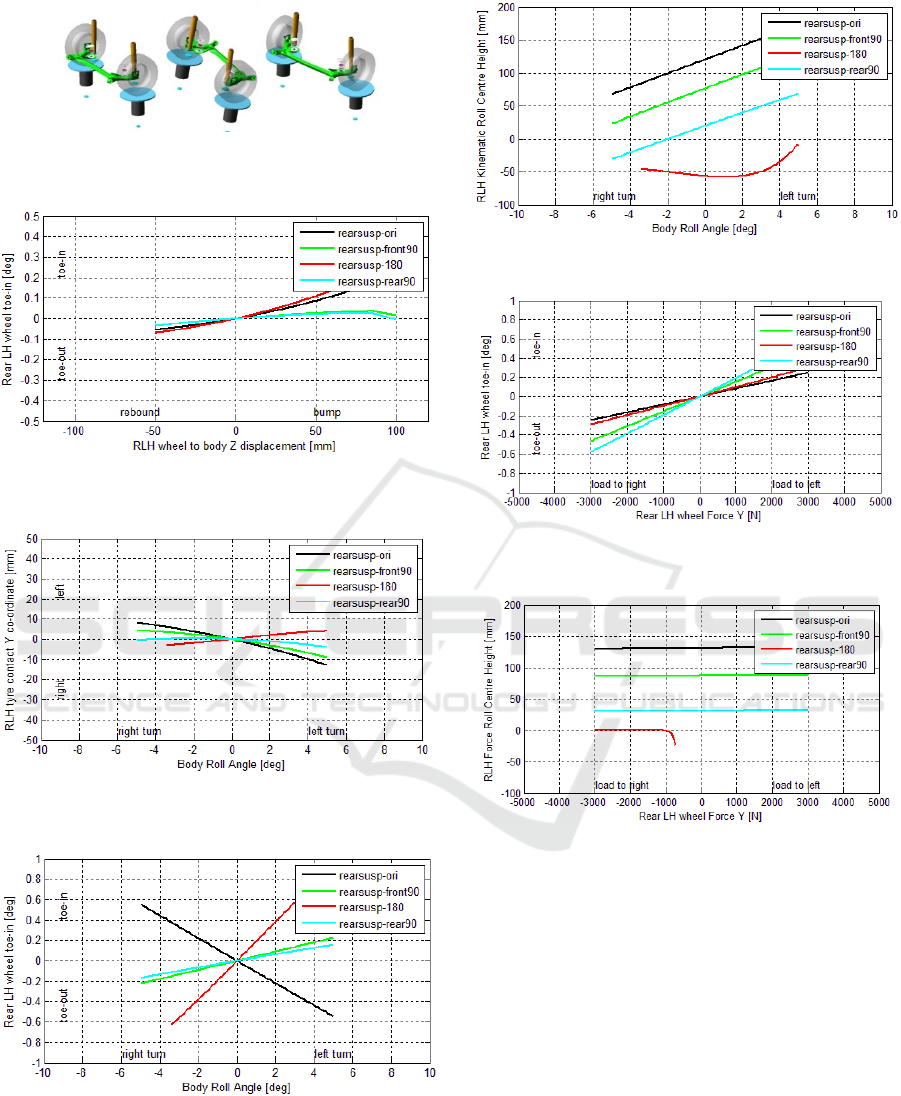
Fig 6. Torsion beam suspension with different opening
direction beams.
Fig 7. Variation of toe angle in parallel wheel jumping
conditions.
Fig 8. Lateral displacement of the tire's grounding point in
rolling conditions.
Fig 9. Variation of toe angle in rolling conditions.
Fig 10. Rolling center height in roll condition.
Fig 11. Variation of toe angle in reverse lateral force
conditions.
Fig 12. The height of the roll center in the same lateral
force conditions.
In the case of parallel wheel jumping and rolling
conditions, the variation of toe angle is significantly
different. In the parallel wheel-jumping condition,
the rate of change of the toe angle between the
forward and backward directions of the opening of
the beam is significantly reduced. Which is not
conducive to the understeer; in the rolling
conditions, the direction of the toe angle changes in
the opposite direction to the original change, which
leads to oversteering of the vehicle and is not
conducive to the vehicle's lane changing
performance; the lateral displacement of the tire's
grounding point is significantly different, When the
opening direction of the beam is upward, the lateral
displacement of the tire ground point is a positive
ICVMEE 2019 - 5th International Conference on Vehicle, Mechanical and Electrical Engineering
82
rate of change, which aggravates the tire wear. In the
rolling conditions and the reverse lateral force
conditions, the height of the suspension roll center is
reduced, especially, when the opening direction of
the beam is upward, the height of the roll center is
zero, even less than zero, which is not conducive to
the steady-state steering performance of the car.
3.2 Beam Position
The torsion beam suspension is a semi-independent
suspension, namely a composite suspension. The
more forward the beam is, the closer the suspension
performance is to the independent suspension.
Conversely, the closer the beam is to the wheel
center, the closer the suspension performance is to
the rigid axle suspension. Because of the structural
constraints, this section will move the beam position
50mm forward and 50mm backward, and compare
them with the initial position. The resulting figure is
as follows:
Fig 13. Reverse lateral force toe angle change.
Fig 14. Same lateral force roll center height.
In the same lateral force conditions, the toe angle
and the roll center height change significantly. The
results can provide reference for model optimization.
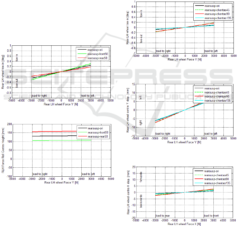
3.3 Bushing Installation Direction
When the vehicle is turning, if lateral load transfer is
not considered, that is, the lateral forces acting on
the left and right tires are the same, the force acting
on the tire's grounding point can be decomposed into
the lateral force acting on the connecting body's
bushing which helps to increase the understeer and
the moment acting on the torsion beam's beam. Due
to the large bushing used for the bushing at the body
joint, the rigidity in the X and Y directions is
different. This section investigates the effect of the
bushing on the K&C characteristics by turning the
bushings at different angles.
Fig 15. Variation of toe angle in the same lateral force
conditions.
Fig 16. Variation of lateral stiffness in the same lateral
force conditions.
Fig 17. Variation of longitudinal stiffness in the same
longitudinal force conditions.
Analysis of KC of Torsion Beam Suspension based on a Vehicle Model
83

The angle of rotation of the bushing at the
connection between the longitudinal beam and the
body has little effect on the characteristics of the
suspension K and has an effect on the characteristics
of the suspension C. From the above figure, we can
see that the installation direction of the bushing has a
greater influence on the toe angle change and
stiffness change in rolling conditions. The change of
the toe angle of the lateral force condition should be
consistent with the direction of the lateral force, and
the change gradient is positive, which is conducive
to the under steering of the vehicle. The stiffness
changes in longitudinal conditions affect the pitch
attitude of the vehicle and affect the smooth
performance of the vehicle.
4 CONCLUSIONS
1. The opening direction of the beam of torsion
beam suspension has significant influence on the
K&C characteristics of the suspension. By adjusting
the opening direction, optimizing variation of toe
angle and height change of roll center, the vehicle
performance can be improved.
2. The beam position of the torsion beam
suspension has a great influence on the roll center
height, which can provides a reference for the design
of the early suspension.
3. In this paper, by changing the beam position
and opening direction, we study their effects on the
K&C characteristics of the suspension. But the
strength and life of the torsion beam are not
analyzed. In the later period, the finite element
analysis of the torsion beam can be added, and the
influence of the beam on the performance of the
vehicle can be studied.
REFERENCES
Chen, J.R, Ma, T.F. (2006) Automotive Structure (Part 2),
P249-230, Beijing, China Communications Press.
Chen, S.M. (1997) Automobile Dynamics (Second
Edition), Beijing, China Communications Press.
Liao, X.H, Su, H.L. (2015) “Optimization Analysis and
Dynamic Characteristics of Torsion Beams”. Machine
Design and Manufacturing, Vol.4, P74-80
Ma, J.J, Xu, G.X, Tong, Y. (1999) “Calculation and
Analysis of the Roll Center for a Double Wishbone
Suspension”, Journal of Hefei University of
Technology, Vol.4, P132-136
Shang Guan, W.B, Tian, Z.L, Wang, X.L. (2009)
“Rubber-metal Rubber in Automotive Suspension
Systems”, Modern Components, Vol.6, P86-88
Sun, H.Y. (2012) Research on K&C Performance Index
Analysis of Suspension Based on Vehicle Handling
Stability. Master, Jilin University.
ICVMEE 2019 - 5th International Conference on Vehicle, Mechanical and Electrical Engineering
84
