
Research and Application of Robot Force Control for Friction Stir
Welding
Yanggui Xin
1
, Ye Huang
1
, Yunqiang Zhao
1, a, *
, Shiyi Gao
1
and Su Li
1
1
Guangdong Welding Institute(China-Ukraine E.O. Paton Institute of Welding), Guangdong Provincial Key Laboratory of
Advanced Welding Technology, Guangzhou, Guangdong, 510651, China
Keywords: Robot, friction stir welding, secondary developed, constant force control, control system.
Abstract: In this paper, the composition, principle and method of robot force control for friction stir welding were
studied. Based on the RSI interface of robot and C++ language, a host computer and control system for
robotic friction stir welding was developed, and on-line monitoring of data, displaying of historical data and
preserving of welding- process data were realized. According to the technological characteristics of robotic
friction stir welding, the constant force control of welding-process was realized by combining traditional
PID control and adaptive control. The results indicated that the secondary developed host computer and
control system had the characteristics of simple operation, comprehensive data monitoring, high precision of
force control and stable welding process.
1 INTRODUCTION
Friction stir welding (FSW) is a solid state joining
technology invented by The Welding Institute in
1991 (LONGHURST, W. R, et.al, 2010). Compared
with traditional fusion welding technology, welding
defects, such as crack and void can be effectively
avoided by FSW. And it has the advantages of high
mechanical properties, small deformation, low
pollution and low energy consumption. Therefore,
FSW is especially suitable for joining aluminum
alloys whose melting points relatively low. For FSW,
welding force is a key parameter. And the
indentation, rotating speed and forward speed of the
welding tool will have a significant effects on the
welding force (LONGHURST, W, et.al, 2011;
MELENDEZ, M, et.al, 2003; MISHRA, R, et.al, 2005;
YUSSOF, H, et.al, 2015; ZHAO, X, et.al, 2008). Usually,
larger indentation can induce, larger the contact area
between welding tool and the base material, as a
result, the welding force is larger.
Robotic welding system integrates advanced
manufacturing technologies such as precision,
flexibility, intellectualization, software application
and development. This is especially suitable for
welding work-piece with complex three-dimensional
surface structure. The welding of complex three-
dimensional surface structure is an important-
direction for the future development of FSW. In
addition, constant Z-axial force is a key parameter
for obtaining stable welding quality. However, due
to the limited load capacity and flexibility of the
robot, it is difficult to ensure the steady downward
force of the welding tool on the work-piece in FSW
process. Therefore, it is of great significance to
ensure the constant of Z-axial force for improving
the quality of robotic FSW.
2 COMPOSITION OF Z-AXIAL
FORCE CONTROL SYSTEM
2.1 Composition of Control System
As shown in Figure 1, FSW control system is
composed of a six-axis robot and its control system,
host computer control system, data acquisition and
processing system, force sensor system, spindle
motor, stirring needle, frequency conversion control
system and Bus control system. Six-axis robot and
its control system have high flexibility, high
trajectory accuracy, and thus the processing of
arbitrary trajectory in space can be realized. It is
important for realizing FSW of complex three-
dimensional surface structure. The host computer
control system is composed of operating interface
system and C++ program. The operating interface
444
Xin, Y., Huang, Y., Gao, S., Zhao, Y. and Li, S.
Research and Application of Robot Force Control for Friction Stir Welding.
DOI: 10.5220/0008870104440449
In Proceedings of 5th International Conference on Vehicle, Mechanical and Electrical Engineering (ICVMEE 2019), pages 444-449
ISBN: 978-989-758-412-1
Copyright
c
2020 by SCITEPRESS – Science and Technology Publications, Lda. All rights reserved
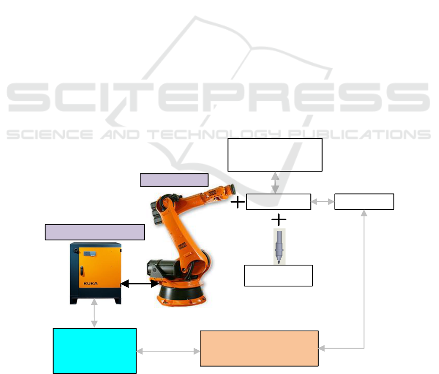
system is used to realize functions, such as welding
process parameters setting, data calling, welding
mode selection, system alarm display, real-time
welding data curve display and data storage and
conversion. C++ program system is used to
communicate with slave system and realize data
exchange. The constant force control of welding
process was realized by the feedback force of C++
program system collected. Data acquisition and
processing system is used to collect and process
force sensing values and transmit to PC by OPC.
Force sensor system are transformed by converter to
measure the Z-axial force value in welding process.
Spindle motor is controlled by frequency conversion
system to realize speed control in welding process.
Bus control system includes Profinet communication
between robot and data acquisition system, RSI
communication between robot and host computer,
OPC communication between data acquisition
system and host computer. It realizes data exchange
between robot control system, host computer system,
data acquisition system and salve system (force
sensor, frequency converter, etc.). These data are
important guarantee to realize the coordinated
operation of the whole system.
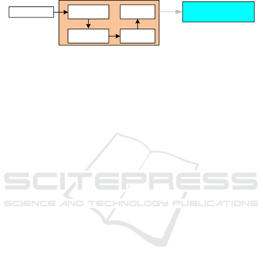
2.2 Data Acquisition and Processing
System
Accurate acquisition and processing of Z-axial force
is an important foundation and guarantee for
realizing constant force in FSW process. Data
acquisition and processing system includes force
acquisition (induction) module, signal amplifier,
signal converter module, and AI data acquisition
module and data processing software. As shown in
Figure 2, the force induction module is used as a
sensitive element (mv level induction), which is
amplified by a signal amplifier. And then it is
converted to the values that can be read by the AI
analog module by signal converting module. Finally,
the collected values are processed and converted by
data software to the actual force values. The data
acquisition and processing system regulates sensitive
signals, including functions of impedance matching,
limiting, zero adjustment correction, isolation, and
wave filter (low pass, power frequency and GSM
filter). And finally converts them into 4-20 mA
signals with strong interference. These signals (4-20
mA signals)are collected and processed by
industrial-level PLC analog module. The influence
of gravity changes of the self-weight of spindle
motor and cable that caused by welding angle
change in the welding process are eliminated. As a
result, the accuracy and stability of data transmission
can be ensured.
Frequency Conversion
Control System
Host PC system
Spindle motor
Robotic control system
Six-axis Robot
OPC
RSI
Welding tool
Welded Parts
Force sensor
Data acquisition and
processing system
Figure 1. Composition of control system.
Research and Application of Robot Force Control for Friction Stir Welding
445
OPC
signal
amplification
Force sensor
Signal
conversion
AI module
Host PC system
(monitor and display)
data
processing
Figure 2. Data Acquisition and Processing.
3 CONTROL MEHTODS AND
PRINCIPLES
3.1 Control Principle of Host PC
The host computer is an important human-computer
interface, and it realizes the functions of parameter
setting, data calling, mode selection, data monitoring,
alarm display and historical data reproduction.
Mature interface development software, such as
Kingview, Intouch and Labview, has the
characteristics of mature, simple development and
short process cycle. However, they cannot directly
develop robot program further. Therefore, these
kinds of software can not directly control the
program of the robot and Z-axis force of the robot.
Based on C++ powerful development language,
robot program will be redeveloped by the KUKA
RSI interface. The host computer exchanges data
with Siemens PLC through OPC that is simple in
communication, strong in reliability and high in
stability, so the force value reading can be realized.
At the same time, the host computer exchanges data
between the robot and the host computer through
KUKA RSI interface. The robot program is
redeveloped using C++ language, and its functions
includes reading the position information of the
robot, PID control and other logical control. Closed-
loop of Z-axis force control can be realized by the
force value that is used as the input and feedback of
the parameters.
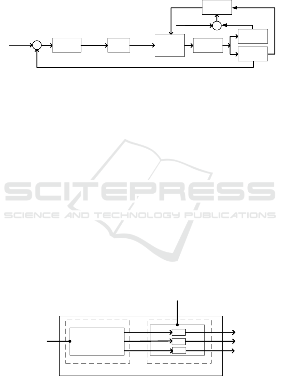
3.2 Control Method of Z-axis Force
3.2.1 Control Principle of Z-axis Force
Figure 3 is schematic diagram of constant force
control. The communication between the robot and
the host computer is realized through the KUKA
RSI interface, and the robot program is redeveloped
using C++ language. In FSW process, after
comparing setting value with actual value of Z-axis
force, the redeveloped program tunes and adjusts
PID parameters by control algorithm combined with
conventional PID and adaptive control, and controls
and adjusts robotic attitude in real time. At the same
time, considering the timeliness of RSI
communication and force feedback, as well as time-
delay of robot execution, it is necessary to fine-tune
and delay the PID parameters according to the
position parameter information of robot feedback, so
that the difference between actual value and setting
value of Z-axis force can be reduced continuously
and Z-axis force can be kept constant within the
range of +10% to achieve the purpose of constant
force control.
3.2.2 Adaptive Control Algorithm
Traditional PID control is one of the earliest
developed control strategies. It is used widely in
process control and motion control because of its
simple algorithm, strong robustness and high
reliability. According to statistics, PID control
methods account for more than 90% in industrial
control. Traditional PID is also the most used and
mature control method in force control. Common
application situation of force control includes robot
grinding, robot polishing, hydraulic pressure control
test bench and force control of robotic FSW. In
process of force control of robotic FSW, the welding
tool needs to overcome the larger axial resistance
because of its direct contact with welded materials.
At the same time the value of axial resistance is
significantly affected by the amount of force,
rotating speed and forward speed of the welding
tool. So there are many uncertain factors which can
influence the Z-axis force. It is difficult to ensure the
system can obtain well welding performance under
all working conditions by using conventional PID,
even the phenomenon of instability and welding
penetration be occur due to the influence of
inappropriate parameters.
ICVMEE 2019 - 5th International Conference on Vehicle, Mechanical and Electrical Engineering
446
Force setting
+
C++language
Control Program
Robotic
Program
Secondary
developed
Proportion
Integration
Differential
Executive
Body
Robotic
parameters
Actual force
-
Force feedback
Position
feedback
Adaptive
algorithm
e1
Parameters
tuning
Force
feedback
Theoretical value
+ -
e2
Figure 3. Control principle of Z-axis force.
In view of the shortcomings of the conventional
PID control methods, and according to the
characteristics of FSW process, a method combining
conventional PID control algorithm with adaptive
control is adopted. This proposed method not only
has the characteristics of high precision, robustness
and reliability of the conventional PID control, but
also increases the flexibility and adaptability of the
system.
The tuning process of parameters of PID
algorithm that adding adaptive control algorithm
mainly refers to the process of pre-setting
parameters and continuous optimization of pre-
setting parameters. Firstly, the pre-setting PID
parameters KP1 (Proportion), KI1 (Integration) and
KD1 (Differential) are determined according to the
setting force. Then, in the process of robot welding,
according to the difference e1 between force
feedback and predicted value (Figure 3), the
optimized PID parameters K'P, K'I and K'D are
determined by comparing, reasoning and choosing.
The optimized PID parameters of this process is
calculated and defined from the parameters that
computed by e1 and summarized by experience.
Finally, according to the e2 that is difference
between actual position and the ideal position of
robot (Figure 3), the final parameters KP, KI, KD
are defined by changing the coefficients of the
parameters K'P, K'I and K'D. In this process, the
increase or decrease of the coefficients are mainly
based on e2 (including positive and negative). The
arithmetic is shown in Figure 4.
4 WELDING PROCESS
RESEARCH AND
APPLICATION RESULT
ANALYSIS
In FSW, the stress of the welding tool is large, this
causes structural deformation of welding equipment
easily and deviation of welding position. Therefore,
it is necessary to control the welding process force
of Z-axial. The control mode of FSW mainly
includes constant displacement and constant force
control. The main purpose of constant displacement
is to obtain a reasonable displacement. However,
due to the sensitive force change in welding process,
a small change may cause a greater force change.
This mode is only applicable to special welding
equipment with larger stiffness. Constant force
control mode can ensure force stably in welding
process, especially for the lack of robotic rigidity,
the constant force control mode can effectively solve
the impact of robotic deformation on welding quality
(YAVUZ, H, 2004).
Comparison, Reasoning
and Selection
K'
p
K'
i
K'
d
K
p
K
i
K
d
e2
F
p
F
I
F
D
e1
Figure 4. Adaptive control algorithm.
Research and Application of Robot Force Control for Friction Stir Welding
447
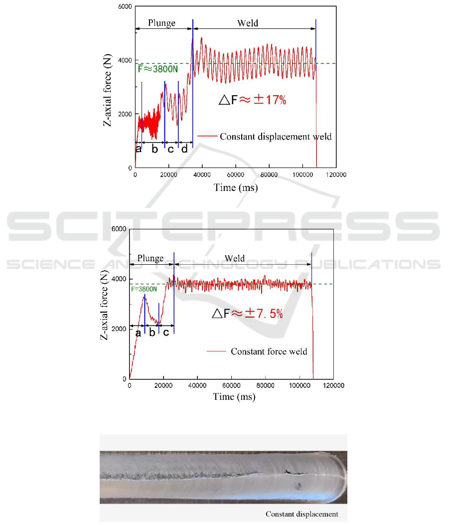
The two modes of constant displacement (welding
depth was 4 mm) and constant force (force was
3800N) were used in FSW of 6063-T4 aluminum
alloy. Weld force cures are shown in Figure 5 and
Figure 6, and weld formations are shown in Figure 7
and Figure 8. For the constant displacement control,
there are obvious groove on the weld surface due to
the large range of force variation, serious shaking in
the plunge and poor stationarity in welding process
caused by the robotic deformation. And for the
constant force control, the weld performance can be
improved significantly, at the same time, it has some
advantages, such as stationary plunge, high precision
and smooth welding process.
Figure 5. Curve of constant displacement.
Figure 6. Curve of constant force.
Figure 7. Weld formation of constant displacement.
ICVMEE 2019 - 5th International Conference on Vehicle, Mechanical and Electrical Engineering
448

Figure 8. Weld formation of constant force.
5 CONCLUSION
(1)A host PC system that was suitable for robotic
FSW by robotic RSI interface and C++ language
was developed, and the data communication among
the robotic control system, host PC system and PLC
control system was realized.
(2)Considering time-delay of robot execution
and technological characteristics of FSW ,the
redeveloped robotic program combines traditional
PID control with adaptive control, controls Z-axial
force can be kept constant within the range of +7.5%
in welding process, and enhances the welding
quality significantly.
(3)The application results show that the
secondary developed host PC system and program
control system have characteristics of friendly
operability and versatility, comprehensive data
monitoring, and reduce the workload of technicians
greatly.
(4)Through data monitoring, curve display,
historical data calling and welding process data
preservation, this research provides important
methods and data support for the optimization of
welding process parameters and the improvement of
welding quality.
ACKNOWLEDGMENTS
The authors are grateful to be supported by the
National Key Research and Development Program
of China (2018YFB1306404), by the Key areas
Research and Development Program of Guangdong
Province (2015B090922011), by the GDAS' Project
of Performance Appraisal (2019GDASYL-0302013),
and the Science and Technology Plan Project of
Guangzhou City (201704030038, 201704030068,
201807010068).
REFERENCES
LONGHURST, W. R., STRAUSS, A. M., COOK, G. E.
(2010) Torque control of friction stir welding for
manufacturing and automation [J]. The International
Journal of Advanced Manufacturing Technology.
LONGHURST, W. R., STRAUSS, A. M., COOK, G. E.
(2011) the identification of the key enablers for force
control of robotic friction stir welding [J]. Journal of
Manufacturing Science & Engineering.
MELENDEZ, M., TANG, W., SCHMIDT, C. (2003) Tool
forces developed during friction stir welding [J].
NASA Technical Reports Server.
MISHRA, R. S., MA, Z. Y. (2005) Friction stir welding
and processing [J]. Materials Science & Engineering.
YUSSOF, H., MISKON, MF, BUSU, N. (2015). A review
of force control techniques in friction stir process [J].
Procedia Computer Science.
YAVUZ, H. (2004) Function-oriented design of a friction
stir welding robot [J]. Journal of Intelligent
Manufacturing.
ZHAO, X., KALYA, P., LANDERS, R. G. (2008) Design
and implementation of nonlinear force controllers for
friction stir welding processes [J]. Journal of
Manufacturing Science & Engineering.
Research and Application of Robot Force Control for Friction Stir Welding
449
