
Design of Hydrofoil Craft for Balikpapan-Penajam Route
Wira Setiawan, Alamsyah, Suardi, R. Jamal Ikhwani and Luthfi Habibi
Institut Teknologi Kalimantan
Keywords: Hydrofoil craft
Abstract: The construction of the Balikpapan-Penajam bridge in order to accelerate the mobilization of goods and
passengers is a policy that needs to be highlighted from a maritime perspective. In addition to the huge
investment costs, this infrastructure work is very likely to turn out sea transportation, which currently
consists of Ro-Ro ferry, Speed boat, and traditional wooden boat. One of the innovations in shipping that
can respond to the challenge is the hydrofoil craft. This vessel is designed as a fast ship by utilizing the lift
force acting on the foil to produce more speed due to the reduced wetted surface area. The design of this fast
ship was carried out using max surf software and CFD simulations to determine foil performance. Based on
the results of the study, it is obtained LoA: 2.4 m, B: 1 m, H: 0.53 m, T: 0.27 m. The Hydrofoil used is
NACA 64 (1) 212 type with Angle of Attack 20 °, Cl/Cd: 1,424, which results in a greater lift force than the
weight at a lifting speed of 17 Knots. The stability analysis shows a maximum GZ value of 0.201 at a heel
angle of 48.2 °, and an Initial GMt at heel angle of 0 ° is 0.444 m and fulfilled the IMO HSC 2000 criteria in
intact stability for monohull and submersed hydrofoil.
1 INTRODUCTION
Balikpapan-Penajam is two cities in East
Kalimantan separated by the sea. This condition is
used as a source of income for Ferry Ro-Ro crossing
vessels managed by the government and, moreover,
individual businesses in the form of fast boats and
traditional wooden boats. In 2019, it is planned to
begin construction of a crossing bridge connecting
the two regions at an expensive cost with a length of
7.35 km. The main reason for the building of this
bridge is to accelerate the mobilization of passengers
and goods that have been able to take between 30-60
minutes by sea transportation.
The challenge experienced so far can be
overcome by using a hydrofoil ship. Foil on ships
can facilitate the operation of the fast ship in deep or
shallow waters. The application is quite simple,
namely by adding foil and strut to the underside of
the ship's hull to provide lift due to the pressure
difference on both sides of the foil (Wonggiawan,
2015). To apply hydrofoil on the ship, an accurate
calculation is needed in determining the type of foil,
the angle of attack, and the placement of the foil
(Slamet and Suastika, 2012). This is needed to
ensure that the hydrofoil design has a greater lift
force than the weight of the ship. In addition, error
calculation can also cause problems in ship
performance, particularly stability (Purwanto et al.,
2010).
Hydrofoil Crafts’ hull shape tends to be V as
typical of the other fast speed ships. It can also be
combined with single and many hull shapes. The
unique advantage of this type of ship is that the
resistance can be reduced by 35% (Sunardi et al.,
2016). This is because of the hull as a component of
the ship is immersed in water so as to cause drag on
the ship, raised in such a way by the pressure
difference that occurs on the two sides of the foil.
The reduced resistance that occurs will result in
lower engine power needed to drive the ship.
Lifting force on the ship as the main concept is
designed so that the foil used can maximize the life
force that is generated greater than the weight of the
ship. Hydrofoil effects of increasing lift on the ship
when speed is added. After the hull is lifted from the
water to the maximum extent, the required lifting
force is constant (Slamet and Suastika, 2012). The
lift force depends on the coefficient of lift generated
by the foil itself.
The coefficient of lift is influenced by the design
of the chamber shape of the foil. The coefficient of
lift produced by a foil varies linearly with a certain
angle of attack (α). To get the maximum lift force,
64
Setiawan, W., Alamsyah, ., Suardi, ., Ikhwani, R. and Habibi, L.
Design of Hydrofoil Craft for Balikpapan-Penajam Route.
DOI: 10.5220/0009405700640068
In Proceedings of the 1st International Conference on Industrial Technology (ICONIT 2019), pages 64-68
ISBN: 978-989-758-434-3
Copyright
c
2020 by SCITEPRESS – Science and Technology Publications, Lda. All rights reserved
the angle of attack parameter and the selected chord
foil are those that have the highest lift and drag ratio
(L / D) (Slamet and Suastika, 2012).
This cannot be separated from the speed of the
ship itself. The greater the speed of the ship, the
greater the lift force (Aji et al., 2016). In terms of
Froude Number, at relatively low speeds (Fn <1.8),
foils actually increase ship resistance while at
relatively high speeds (Fn> 1.8), foils reduce ship
resistance (Sunardi., 2016).
Another thing to note is that the angle of attack
configuration must be precise. Failure to make
correct adjustments will cause the hull to collide
with sea level, which will affect the stability of the
ship (Purwanto et al., 2010). The position of foils
supported by strut also greatly affects the resistance
and stability of the ship. For a single hydrofoil, the
most optimum position is just below the CG of the
ship to reduce the resistance (Sunardi et al., 2016).
While the position of fore hydrofoil was 3/5 Lpp
from LCG (Slamet and Suastika, 2012)
However, besides all the technical aspects
described above, it is also important to discover the
limit of the angle of attack where the ratio of lift
coefficient/drag coefficient still provides an
advantage that affects the lifting force of the foil.
2 METHOD
The ship’s hull is designed by using max surf
modeler software. The dimension of the ship used is
the same as the Balikpapan-Penajam crossing fast
boat. Before being built, the design is analyzed both
related to resistance and stability, also by using the
Maxsurf resistance and Maxsurf stability software
packages. Ship resistance is obtained by using two
Savitsky method to predict the engine power needed
at a maximum speed of 30 knots. Whereas stability
for the fast boat is calculated based on the criteria of
code for the safety of High-Speed Craft (HSC 2000)
both for monohull and submersed hydrofoil issued
by the International Maritime Organization (IMO).
On the other hand, to determine the appropriate
foil to the ship that has been designed, the foil that
has the highest Cl / Cd ratio was selected to generate
an optimum foil performance. The types of foil
compared were NACA 23012, NACA 0015, NACA
2412, and NACA 64A12 with various angles of
attack by using Computational Fluid Dynamic
simulation.
Cl=
L
1
2
ρ. v
2
.AP
(1)
Where :
L: Lift Force (N)
ρ: Fluid Density (Kg/m3)
Cl: Lift Coefficient
v : Velocity (m/s)
AP: Plan Area (m2)
Cd=
D
1
2
ρ. v
2
.AP
(2)
Where :
D: Drag Force (N)
ρ: Fluid Density (Kg/m3)
Cd: Drag Coefficient
v : Velocity (m/s)
AP: Plan Area (m2)
3 RESULT & DISCUSSION
3.1 Design
The dimension of the hydrofoil vessel is created
according to the size of the Balikpapan Penajam
crossing fast ship. It is needed in order to facilitate
the shipbuilding process, which will be carried out in
further research.
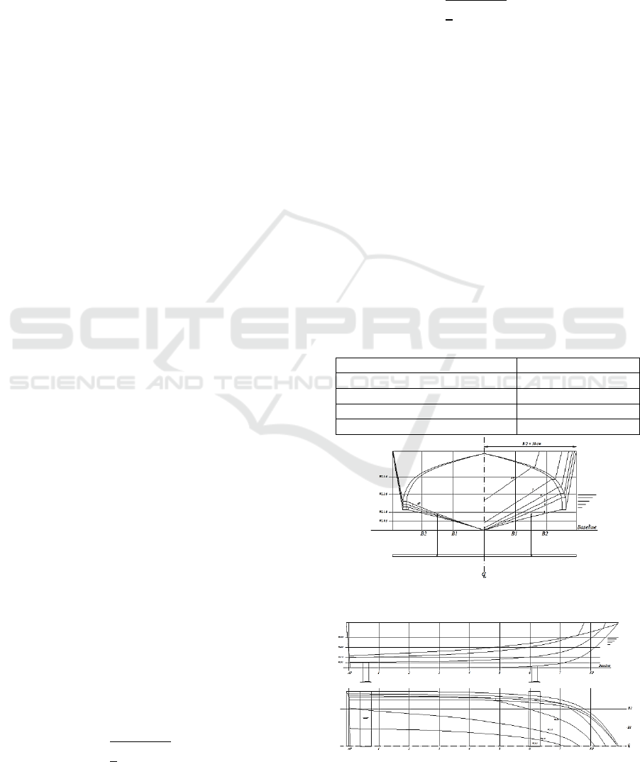
Table 1: Main Dimension of Hydrofoil Craft
Item Dimension
Length Overall (LoA) 2.40 m
Breadth (B) 1.00 m
Depth (H) 0.53 m
Draft (T) 0.27 m
Figure 1: Body Plan of Hydrofoil Craft
Figure 2: Profile and Plan View of Lines Plan
Design of Hydrofoil Craft for Balikpapan-Penajam Route
65
Due to the dimension, a V-type fast hull with a
hard chine is designed that separates the bottom and
side hull with a 14 ° deadrise, and the stern is likely
to be raked. The coefficient block is made slim 0.45
but still notice the load capacity, while the
coefficient of midship is 0.75. Displacement of ships
designed with Fiber Reinforced Plastic (FRP)
materials is 0.33 tons with LWT and DWT of 0.06
tons 0.27 tons, respectively. The area of the wetted
surface is 2,574 m2, which will be 0 when the ship is
in lifting condition. For the starting point of the
longitudinal stability, the ship has a stern trim of
0.07 °.
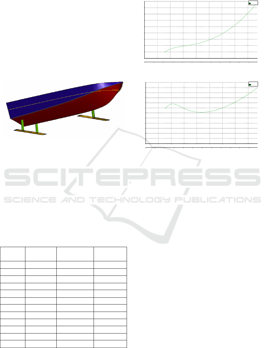
Figure 3: Isometric View of Hydrofoil Craft
3.2 Resistance
Resistance is the most important indicator that can
be significantly reduced on hydrofoil craft. The
prediction is made by using the Savitsky method up
to 100% Maximum Continuous Rating at 30 knots.
Based on the Maxsurf Resistance simulation results,
the resistance of 0.72 - 0.88 kN is obtained at a
service speed of 25-30 knots with engine power
requirements of 12.5-18.4 HP, as shown in table 2
and figure 4.
Table 2: Resistance of Hydrofoil Craft
Speed
(Knot)
Froude
Number
Resistance
(N)
Power
(HP)
8 1.588 776.18 4.284
10 1.986 752.78 5.193
12 2.383 690.90 5.720
14 2.780 643.36 6.214
16 3.177 618.91 6.832
18 3.574 615.07 7.638
20 3.971 628.92 8.678
22 4.368 657.75 9.983
24 4.765 699.40 11.58
26 5.163 752.27 13.493
28 5.560 815.13 15.746
30 5.957 887.07 18.359
Figure 4: Power v Speed Curve
Figure 5: Resistance v Speed Curve
Figure 5 explains that as most ships commonly, a
hump occurs at a speed of 8.5 knots and increases
sharply in the speed range of 20-30 knots. Humps
can occur due to wave patterns that are longer than
the length of the ship. Hump is a bad condition to
operate the ship because it generates a greater wave-
making resistance at low speeds so that it consumes
more fuel.
3.3 Stability
Intact stability is calculated by using three criteria,
namely High-Speed Craft (HSC) 2000 Annex 8 for a
monohull, HSC 2000 Submersed hydrofoils Hull
borne mode, and HSC 2000 Submersed hydrofoils
Transitional and foil borne modes. The results of the
max surf software simulation present stability with
displacement of 0.33 tons, LCG = 0.923 m, VCG 0.1
m, and TCG 0.0 m, thus it is obtained data that meet
all aspects of safety, for example, maximum GZ
0.201 at a heel angle of 48.2° and Initial GMt at 0°
heel angle is 0.444 m. Special for hydrofoil, wind
heeling, and angle of equilibrium with passenger
crowding also meet the requirements.
0
3
6
9
12
15
18
21
24
27
0 4 8 12 16 20 24 28 32
0 0.5 1 1.5 2 2.5 3 3.5 4 4.5 5 5.5
Sav itsky Planing
Speed kn
Power hp
Beam- based Froude number
Legend
Sav itsk y Plan ing
0
100
200
300
400
500
600
700
800
900
1000
1100
1200
0 4 8 12 16 20 24 28 32
0 0.5 1 1.5 2 2.5 3 3.5 4 4.5 5 5.5
Sav itsky Planing
Speed kn
R esistance N
Beam-based Froude number
Legend
Sav i ts ky Planing
ICONIT 2019 - International Conference on Industrial Technology
66
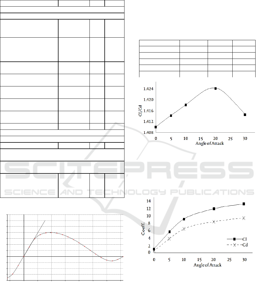
Table 3: Intact Stability Result
Criteria Value Units Actual
Code: HSC 2000 Annex 8 Monohull. Intact
1.1 Weather criterion from IMO A.749(18)
The angle of steady heel
shall not be greater than
(<=)
16.0 deg 1.0
The angle of steady heel /
Marginline immersion
angle shall be less than
(<)
80.00 % 15.85
Area1 / Area2 shall not be
less than (>=)
100.00 % 261.48
1.2 Area 0 to 30 or
GZmax
3.1510 m.de
g
3.2567
1.3 Area 30 to 40 1.7190 m.de
g
1.9102
1.4 Max GZ at 30 or
greater
0.200 m 0.201
1.5 Angle of maximum
GZ
15.0 deg 48.2
1.6 Initial GMt 0.150 m 0.444
HSC 2000 Submersed hydrofoils. Hull borne mode
Criteria: Angle of equilibrium
Wind heeling (Hw) 10.0 deg -0.2
HSC 2000 Submersed hydrofoils. Transitional and foil
borne modes
Annex 6 1.2.2.3 Transitional Mode - Angle of equilibrium
with passenger crowding
- The angle of equilibrium
with passenger crowding
shall not be greater than
(<=)
12.0 deg -0.2
Figure 6: GZ Curve
3.4 Hydrofoil Performance
Four types of hydrofoil were tested to determine the
performance of the lift per drag ratio generated. It is
known that the displacement of the ship is 0.33 tons
or equal to 3237.3 N. The force is charged to the
typical two foils so that the load per foil is 1618.65
N.
Based on the CFD simulation results, it is
selected NACA 64 (1) 212 foil which shows Cl and
Cd by using equations 1 and 2 as the data below:
Table 4: Cl and Cd at Various Angle of Attack
Angle of Attack Cl Cd Cl/Cd
0° 1.01441 0.71942 1.41004
5° 5.48150 3.87586 1.41427
10° 9.23589 6.51238 1.41821
20° 11.97510 8.40703 1.42442
30° 13.32200 9.41710 1.41466
Figure 7: Cl/Cd v Angle of Attack
Figure 7 shows the limit of the advantage point
of a foil. It presents that the angle of attack at 20°
provides the highest cl/cd ratio and decreases
sharply to 30°. Hence, the foil at the angle of attack
at 20° is selected to support the hull.
Figure 8: Cl and Cd v Angle of Attack
4 CONCLUSIONS
Based on the results of the study, it is obtained the
main size of the hydrofoil craft, namely LoA: 2.4 m,
B: 1 m, H: 0.53 m, T: 0.27 m. The foil used is
NACA 64 (1) 212 at an Angle of Attack of 20 ° with
a span length of 1 m, which results in Cl / Cd 1.42.
Whereas the engine power needed at 30 knots speed
-0.2
-0.15
-0.1
-0.05
0
0.05
0.1
0.15
0.2
0.25
0.3
0.35
-25 0 25 50 75 100 125 150 175
Max GZ = 0.201 m at 48.2 deg.
1.6 Initial GMt GM at 0.0 deg = 0.444 m
Heel to Starboar d deg.
GZ m
Design of Hydrofoil Craft for Balikpapan-Penajam Route
67

is 18.4 HP. In addition, stability meets the IMO HSC
code criteria for monohull and hydrofoil craft.
To sum up, the hydrofoil as an alternative fast
boat crossing Balikpapan Penajam can be declared
feasible to proceed to the prototype building stage
with FRP material. If the test results are satisfactory,
it can be recommended an advanced design of a ro-
ro hydrofoil ferry boat that can load passengers and
goods in large quantities, including the cost
investment calculation.
REFERENCES
IMO., 2000. International Code of Safety for High Speed
Craft
Wonggiawan F, Budiarto U, Rindo G, 2015. Studi
Perancangan Hydrofoil Kapal Penumpang Untuk
Perairan Kepulauan Seribu. Jurnal Teknik ITS. vol. 1,
pp. 41-46
Slamet A.S, Suastika K. I, 2012. Kajian Eksperimental
Pengaruh Posisi Perletakan Hydrofoil Pendukung
Terhadap Hambatan Kapal. Jurnal Teknik ITS. vol. 1,
pp. 51-54
Purwanto D, Hantoro R, Utama I., 2010. Kajian Perbaikan
Performansi Pada Hydrofoil Kapal Cepat Dengan
Penambahan Sirip Menggunakan Metode
Computational Fluid Dynamic (CFD). Jurnal Teknik
ITS. vol. 1, pp. 25-29
Sunardi , Bambang S, Ali M , 2016. Laminasi Fiberglass
Untuk Memperbaiki Kapal Ikan Kayu Di Kecamatan
Lekok, Kabupaten Pasuruan, Jawa Timur. Jurnal
Ilmiah Rinjani Vol. 4, pp 68-72
Aji S, Irfan S. A, dan Amiadji, 2016. Analisa Sudut
Serang Hidrofoil Terhadap Gaya Angkat Kapal
Trimaran Hidrofoil Menggunakan Metode
Computational Fluid Dynamics (CFD). Jurnal Teknik
ITS. vol. 5, No. 2, pp.402-407
ICONIT 2019 - International Conference on Industrial Technology
68
