
Heart Beat Monitoring Device with an Optical Sensor
Budiani Fitria Endrawati, Barokatun Hasanah, Vicky Mudeng, Kresna Prasetya Pamungkas, Ahmad
Maulana Rizki, Ramadhani and Ezekiel Miracle Bintang A.
Institut Teknologi Kalimantan
Keywords: Heart rate monitoring, Optical sensor, Fingertip, Wrist
Abstract: Heartbeat measurement system is an important issue to monitor the health condition of the human being. In
normal resting, heart rate will be beaten between 60 to 100 beats per minute (bpm) depending on the age
and physical condition. Through heart rate monitoring, several severe diseases can be discovered as
preventive action of mortality; for instance, heart failure. The work within this study presents a developed
heartbeat monitoring (HBM) using an optical proximity sensor to measure heart rate. It involves both the
measuring on the fingertip and wrist for comparison. The proposed HBM detects the blood flow through the
index finger, while the wrist measurement employs a pedometer in a smartwatch of Xiomi Mi Band 3. An
HBM consists of an optical sensor with a light source and detector, a microcontroller module of NodeMCU
ESP8266, and an organic light-emitting diode (OLED) display. The experimental tests measure the
heartbeat with two conditions, such as no activity and after activity states; and with three different ages. The
results indicate that proposed HBM is suitable for monitoring heart rate and obtained data that is possible to
provide via mobile and internet applications.
1 INTRODUCTION
The new efforts for developing mobile medical
devices with low production costs emerge to be a
new focus in the biomedical field. Health monitoring
is an important issue due to it can be discovered the
diseases, physical condition, blood pressure, and
heart health. The heart pulse can be monitored due
to there is a change in the blood density affected by
the heart pumping the blood to the whole body
(Arulananth, 2017).
The most common sensor to detect the heart rate
is pulse oximeter for measuring oxygen saturation in
the blood. It illuminates the skin and measures the
variation of the absorbed light (Jubran, 2015). It
applies a near infra-red (NIR) light with a
wavelength between 600 to 1000 nm; therefore the
light can be penetrated the tissue (Mudeng, 2018).
The designing of heart rate monitoring by
implementing the different microcontrollers have
been proposed for clinical trials. The combination of
the proximity sensor, including a light source and
detector with a signal extraction, pulse
amplification, as well as display circuit, generated
less time consuming and efficient cost in clinical
pulse detection (Hashem, 2010). A measurement
algorithm was applied in a microcontroller
interfacing with analog to digital converter (ADC)
and oximeter. Furthermore, this system utilized a
field-programmable gate array (FPGA) to produce a
control signal. With this system, the heart rate was
detected in the normal state of human activity and
had a low power dissipation (Keat, 2016).
A comparison of personal health monitoring
devices has been conducted. A sensor with a chest
strap, fitness tracker, smartwatch, and the
photoplethysmography (PPG) on the smartphone
feature was investigated to determine the highest
accuracy for each device. The chest strap showed
better accuracy due to the results were similar to the
recognized medical devices. On the other hand,
fitness trackers and the smartwatch had accurate
results in a little physical movement. The low
accuracy occurred when there were several
movements, particularly on the wrist. The light
intensity, in this case, will inaccuracy measure the
density of blood due to the change of scattered and
absorbed light through the skin. Fluctuation heart
rate measurement by employing PPG occurred even
in a little activity (Pessemier, 2017). The multi-
measurement system, with an average of a set of
data, is a proper option to be investigated for
Endrawati, B., Hasanah, B., Mudeng, V., Pamungkas, K., Rizki, A., Ramadhani, . and Bintang A., E.
Heart Beat Monitoring Device with an Optical Sensor.
DOI: 10.5220/0009445102210225
In Proceedings of the 1st International Conference on Industrial Technology (ICONIT 2019), pages 221-225
ISBN: 978-989-758-434-3
Copyright
c
2020 by SCITEPRESS – Science and Technology Publications, Lda. All rights reserved
221

yielding precise results in the heartbeat sensing
system.
In addition, a tiny pressure sensor but with
efficient measurement and flexible shape developed
to cope with comfortable and low-cost solutions in a
mobile medical device (Shu, 2015). An idle heart
rate, compared to the threshold heart rate, was
presented to determine the heart condition using the
collected data, which was stored in the database. The
apparatus collected data from an analog sensor, then
transfer them to the database via the internet (Farin,
2016). With new technology, the heart rate detection
can be extracted by ultra-wideband (UWB) impulse
radar without touching and placing the sensor
around the body (Cho, 2018). The telemonitoring
analyzing with heart rate sensor node was
demonstrated for wireless body sensor networks
(WBSNs) (Fouad, 2017), as well as continuous
monitoring applied bandpass filter (BPF) based on
light-dependent resistor (LDR) as a signal receiver
and light-emitting diode (LED) as a light transmitter
(Cohen, 2017).
In this study, we present the heartbeat monitoring
(HBM) by implementing a non-invasive heart rate
sensor with a wavelength of 609 nm involving an
infra-red (IR) LED and a photodetector. The heart
pulse, then processed by the NodeMCU ESP8266
microcontroller module. Based on the data obtained
from the proposed device, we compare them with a
pedometer in a smartwatch of Xiomi Mi Band 3 to
verify the heartbeat in no activity and after activity
conditions.
2 METHODS
2.1 Designed System
Estimating the heart condition through the
placement of the sensor on the index finger is the
aim of HBM. The sensor has embedded a filter and
amplification circuits. Therefore, it can be interfaced
directly to the microcontroller module. Also, it was
provided in a sensor pair packaging composed of
two primary components, namely an IR LED and a
photodetector.
The low power IR LED is capable of penetrating
the skin of the human body due to it has a
wavelength of NIR. The NIR light penetrates inside
the fingertip, hence some of the light will be
scattered and absorbed. The blood pumping from the
heart induces the variation in light intensity: the
higher blood velocity, the higher heart bpm, and vice
versa. The photodetector has to receive the light
returning from inside the fingertip accurately. Figure
1 depicts the illustration of an index finger on the
sensor to determine the heart rate.
Figure 1: Illustration of HBM fingertip measurement.
The sensor counted the pulse when fingertip of
the index finger touching well it. As can be seen in
Figure 1, the blood pressure analog data in the artery
representing by the red line will be converted to the
heart rate in the embedded algorithm inside the
microcontroller. This mechanism drove us to
develop medical apparatus in HBM purposes.
Besides, we discovered that ischaemic heart disease
contributed to reducing the expectancy of men
respecting women is 0.84 years (World Health
Organization, 2019).
We designed the system with a pulse heart rate
sensor, NodeMCU ESP8266 microcontroller
module, and an organic LED (OLED) display to
interpret an HBM device, as shown in Figure 2. As
explained previously, the data from the sensor was
transferred directly to the microcontroller, and there
was an ADC processing with the counting processes
of the raw data from the sensor to be a bpm. Next,
the bpm and waveform displayed in OLED.
PulseHeart
RateSensor
XD‐58C
NodeMCU
LoLinV3
OLED
128x64
HeartBeat
bpm
Figure 2: The proposed full system.
For detecting the heart rate, not all pins of
NodeMCU was used. The sensor and OLED needed
3 volts for the power source, which was provided by
two pins of NodeMCU. Additionally, only one pin
in the microcontroller was necessary for connecting
the signal (S) pin on the sensor to the A0 pin. SCL
and SDA pins on OLED were interfaced to D0 and
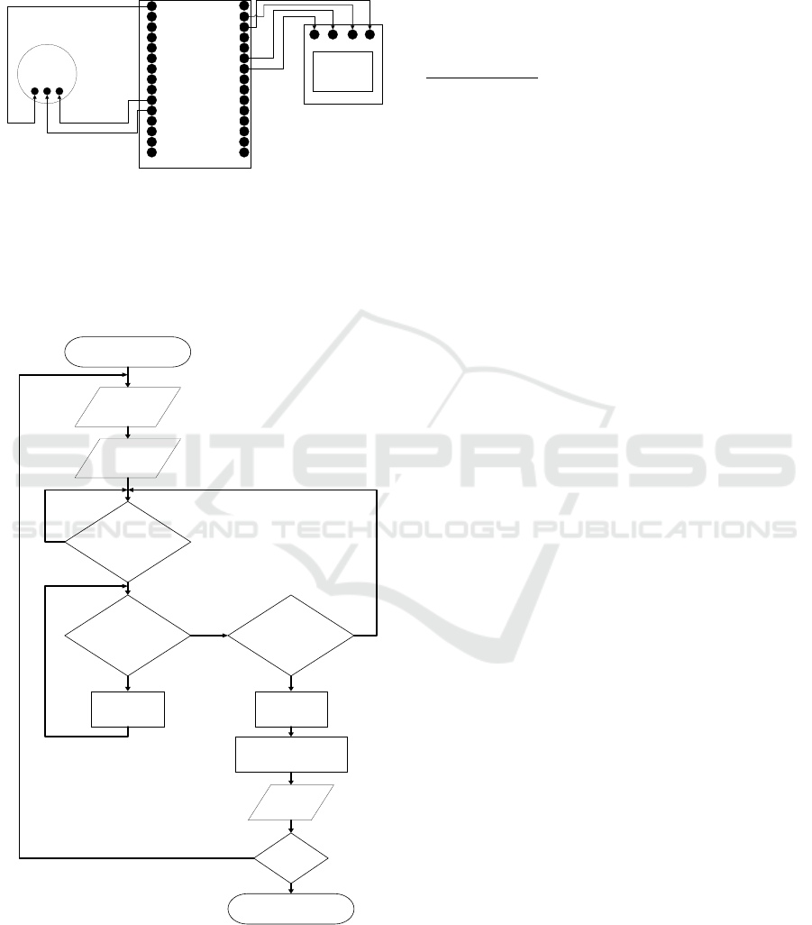
D1, respectively. Figure 3 shows the wiring diagram
of HBM. We tried to design the measurement
system with minimum electronic components for
considering in the future work to provide efficient,
low cost, tiny, portable, and mobile HBM
instruments.
The used system can be modified in the data
transmission due to NodeMCU is a microcontroller
module equipped by the Wifi module. It enables to
ICONIT 2019 - International Conference on Industrial Technology
222
send the obtained data from the sensor to the
planned database; therefore, not only the person who
is worn, and this device can monitor the heart
condition, but also the others.
A0
G
VU
S3
S2
S1
SC
SO
SK
G
3V
EN
RST
G
VIN
D0
D1
D2
D3
D4
3V
G
D5
D6
D7
D8
RX
TX
G
3V
NodeMCU
S+
‐
OLED
128x64
PulseHeartRate
SensorXD‐58C
GND
VCC SCL SDA
Figure 3: The schematic of HBM.
2.2 Algorithm
In this work, the software implementation was
applied in the microcontroller. The flowchart for
HBM is shown in Figure 4. First, analog data from
START
HeartBeat
=Value
BeatComplete?
Time=Time+1
Display
bpm
Value<LowerThreshold
(500)
Value>UpperThreshold
(550)
Time=0
Time=Time+1
END
NO
YES
YES
NO
YES
NO
NodeMCUOFF?
NO
YES
bpm=60/(Value/1024)
YES
Figure 4: Flowchart for HBM.
The sensor will become the input for the
microcontroller. The input indicates a heartbeat in a
digital signal due to the role of ADC. We count the
time was 0 for the initial condition. Then, we
determined two threshold values, for instance, 500
as lower and 550 as upper thresholds, respectively.
In each process, the algorithm will increase the time
by one. The NodeMCU has 10 bit ADC or 1024 in
decimal; hence, the digital data has to be divided by
1024. Afterward, bpm is obtained from
/
. These processes are existed to
measure the heart rate in our HBM.
3 RESULTS
We compared the designed measurement system
with a smartwatch made by Xiomi Mi Band 3. The
experimental set up conducted by no activity and
after activity states. Further, we invited three
volunteers to participate in the tests. An adolescent
14 years old and two adults with 20 and 49 years old
were investigated using two devices simultaneously.
Our HBM was placed on the fingertip of the index
finger while the smartwatch was worn on the wrist.
To ensure the test results, we monitored the heart
beat for the right hand and left hand, alternately with
three times data retrieval.
The HBM and smartwatch first put on the right
hand in the no activity state. Then, we monitored the
heartbeat and comparing two of a set of data from
HBM and smartwatch. In the state of after activity,
we restricted only in a little movement of ran on the
spot for 10 seconds. Nonetheless, we allowed the
resting times for 10 to 15 minutes to proceed to the
next trial tests.
Figure 5 demonstrates the HBM system for
measuring the heart rate. Figure 5 (a) depicts the
sensing on the left hand with two devices on the no
activity state. The left figure of Figure 5 (b) shows
the index finger illuminated by the light source from
the sensor. Moreover, the right figure in Figure 5 (b)
indicating the measured heart rate is 82 bpm.
Table 1 shows the comparison between HBM
and smartwatch results for 14, 20, and 49 years old
with no activity and after activity condition on the
right hand. The delta measurement of HBM and
smartwatch maximum was 10 bpm with no activity
occurred for 14 years old and 49 years old on the
third data retrieval. The difference maximum
measurement data was at 14 bpm for 14 years old
after activity on similar data retrieval.
Heart Beat Monitoring Device with an Optical Sensor
223

Table 1: Results of the right hand.
Activity HBM Smart Watch
Heart Rate 1
(bpm)
Heart Rate 2
(bpm)
Heart Rate 3
(bpm)
Heart Rate 1
(bpm)
Heart Rate 2
(bpm)
Heart Rate 3
(bpm)
None
14 years old 71 70 69 73 70 79
20 years old 69 66 77 72 66 72
49 years old 82 64 84 88 64 74
After
14 years old 74 86 88 74 86 74
20 years old 83 84 84 73 67 79
49 years old 94 74 87 98 64 84
Table 2: Results of the left hand.
Activity HBM Smart Watch
Heart Rate 1
(bpm)
Heart Rate 2
(bpm)
Heart Rate 3
(bpm)
Heart Rate 1
(bpm)
Heart Rate 2
(bpm)
Heart Rate 3
(bpm)
None
14 years old 73 71 71 71 73 79
20 years old 71 68 75 73 68 74
49 years old 80 64 85 89 64 77
After
14 years old 76 84 90 76 89 76
20 years old 85 87 86 78 69 79
49 years old 93 72 89 99 64 86
(a)
(b)
Figure 5: HBM hardware on a view of (a) left hand and (b)
zooming in the index finger with showing bpm and
waveform.
Table 2 shows the comparison between HBM
and smartwatch on the left hand. The delta
measurement of HBM and smartwatch maximum
was 9 bpm with no activity occurred for 49 years old
on the first data retrieval? The difference maximum
measurement data was at 18 bpm for 20 years old
after activity on the second data retrieval.
The considerable results were generated by the
proposed HBM. The result variations were possible
due to the sensitivity of photodetector. Nevertheless,
it has a similar potentiality comparing with the
commercial smartwatch.
4 CONCLUSIONS
In this study, a competitive HBM system has been
proposed in measuring the heart rate. Farther, the
future work is considered to improve the
performance of proposed HBM through the
packaging model, and data transmission system via
mobile and internet applications wirelessly.
According to the experimental results, they indicate
that HBM is feasible to be a secondary wearable
medical apparatus to check the data of heart rate for
preventive action in the mortality caused by health
problems, especially heart failure or disease. Over
and under the results of HBM comparing to the
smartwatch, results were occurred and could not be
accurately determined; however, it remains effective
ICONIT 2019 - International Conference on Industrial Technology
224

for heart rate screening. Hereafter, the results can be
initial progress for intensifying the development of
HBM as the medical device.
ACKNOWLEDGMENT
This research was financially supported by the
Ministry of Research, Technology, and Higher
Education of the Republic of Indonesia through
grant 007/SP2H/LT/DRPM/2019.
REFERENCES
Arulananth.T. S, B. Shilpa, 2017. Fingertip based Heart
Beat Monitoring System Using Embedded Systems. In
International Conference on Electronics,
Communication and Aerospace Technology. IEEE.
Cho, H. S., Y. J. Park, 2018. Detection of Heart Rate
through a Wall Using UWB Impulse Radar. Journal of
Healthcare Engineering, Vol. 2018, No. 4832605.
Cohen, Z., Shyqyri Haxha, 2017. Optical-Based Sensor
Prototype for Continuous Monitoring of the Blood
Pressure, IEEE Sensors Journal, Vol. 17, No. 13.
Farin N. J., S. M. A. Sharif, I. Mobin, 2016. An Intelligent
Sensor Based System for Real Time Heart Rate
Monitoring (HRM). Intelligent Control and
Automation, Vol. 7, No. 2.
Fouad, H., H. Farouk, 2017. Heart Rate Sensor Node
Analysis for Designing Internet of Things
Telemedicine Embedded System, Vol. 4, No. 1.
Hashem, M. M. A., R. Shams, Md. A. Kader, Md. A.
Sayed, 2010. Design and Development of a Heart Rate
Measuring Device Using Fingertip. In International
Conference on Computer and Communication
Engineering. IEEE.
Jubran, Amal, 2015. Pulse Oximetry. Critical Care, Vol.
19, No. 1.
Keat, L. C., A. B. Jambek, U. Hashim, 2016. Heart-rate
Monitoring System Design and Analysis Using a Nios
II Soft-core Processor. International Journal of
Electronics and Telecommunications, Vol. 62, No. 3.
Mudeng, Vicky, Y. Priyanto, A. Giyantara, 2018. Image
Reconstruction for Frequency-Domain Diffuse Optical
Tomography. Turkish Journal of Electrical
Engineering and Computer Sciences, Vol. 26, No. 5.
Pessemier, T. D., L. Martens, 2017. Measuring Heart Rate
with Mobile Devices for Personal Health Monitoring.
In the 12th International Conference on Internet and
Web Applications and Services. IARIA.
Shu Y., C. Li, Z. Wang, W. T. Mi, Y. X. Li, T. L. Ren,
2015. A Pressure Sensing System for Heart Rate
Monitoring with Polymer-Based Pressure Sensors and
an Anti-Interference Post Processing Circuit, Vol. 15,
No. 2.
World Health Organization, 2019. World Health Statistics
Overview 2019: Monitoring Health for the SDGs,
Sustainable Development Goals, World Health
Organization. Geneva.
Heart Beat Monitoring Device with an Optical Sensor
225
