
Comparison of Anti-sway Gantry Crane Control System based on
PID and Fuzzy Logic Control
Primarratna Setiyopamuji, Fuad Fahmi, Porman Pangaribuan, Erwin Susanto
and Agung Surya Wibowo
Electrical Engineering Department of Telkom University, Telekomunikasi Street Number 01, Bandung Regency,
Indonesia, 40257
Keywords: Anti-sway, Gantry Crane, Fuzzy Logic, Proportional-Integral-Derivative.
Abstract The development of industry involves automation as the core of the manufacturing process and material
handling. One of the automatic applications called gantry crane used for things moves from one place to
another place. The problem arises when the gantry crane makes a movement to carry some loads. The cable
which connects the crane and load may make sway continuously. This sway is unwanted because it will be
dangerous to people or the environment near the gantry crane. Moreover, the load could be dropped, or the
worse thing is the cable could be broken. As a result of that, the sway should be eliminated faster. This research
purposed to design an antisway system that will reduce or make the sway is gone quickly. PID and Fuzzy
Logic are used as the method of the controller for the implementation of anti-sway. The result showed that
the sway could decrease in two aspects. The first is the duration of sway reduced from 158,35 to 3,885 second
by fuzzy logic and from 82 to 7 seconds by PID. The second is maximum sway was also reduced from 17,52
to -8,09 by fuzzy logic and from -12,59 to 4.22 by PID.
1 INTRODUCTION
Gantry crane is used in many industries or harbor to
do load movement easily. The conventional crane
sometimes is not safe because there is a way which
makes an operator must be careful to control the crane
manually. The sway is hardly attenuated, and it
becomes a challenging problem for engineers on how
to design a control system that works for reducing the
sway in gantry crane. The system which can decrease
and attenuate the sway is called anti-sway. It will run
automatically together with control of crane's
position.
Some methods have been developed to handle or
to implement anti-sway. There are fuzzy logic
controller [1], [2], and PID [3]. However, we do not
believe in the assumption that a controller method is
better than another method. So, this research would
compare two popular methods applied in the anti-
sway system. In the experiment, the response of the
sway degree would be showed and plotted with
different parameters and conditions.
2 GANTRY CRANE
Cranes are usually used for moving heavy goods
transportation in harbor, manufacture, and high
construction building project. One of the types of
cranes is a gantry crane. That has two holders on both
sides and one rail between the holders. Most of the
gantry cranes are operated manually, which may
swing the heavy load like a pendulum. The swing
needs to be balanced quickly so that the sway will not
be harmful, and the goods are moved faster. Figure 1
below shows the prototype of the gantry crane used
in this research.
Figure 1: Prototype of Gantry Crane.
Setiyopamuji, P., Fahmi, F., Pangaribuan, P., Susanto, E. and Wibowo, A.
Comparison of Anti-sway Gantry Crane Control System based on PID and Fuzzy Logic Control.
DOI: 10.5220/0009490302650271
In Proceedings of the 1st International Conference on Industrial Technology (ICONIT 2019), pages 265-271
ISBN: 978-989-758-434-3
Copyright
c
2020 by SCITEPRESS – Science and Technology Publications, Lda. All rights reserved
265

In this prototype, the control method is used as the
control of position and anti-sway. Generally, the
system is a closed-loop with two feedbacks. One
sensor is used as a sway sensor that detects the angle
of sway and another one used as displacement
sensing. Figure 2 describes the block diagram for
control of position with anti-sway.
Figure 2: Closed-Loop Blok Diagram.
Based on Figure 2, it is showed that the overall
system also has two controllers and one actuator. The
DC motor is used as the actuator. The output of both
controllers would be accumulated as a PWM signal
and fed into the actuator.
3 GANTRY CRANE MODELING
Figure 3 shows the physical model and all of the
parameters used for deriving the mathematical model.
The input is force applied in the cart while the outputs
are (the angle of sway) and
(the position of cart).
Figure 3: Gantry Crane Model.
Note :
= Cart mass (kg)
= Crane mass (kg)
l = Rotational axis length to center of mass (m)
= Pendulum vertical angle (rad)
g = Acceleration of gravity (m/s2)
= Cart coordinate position (m)
By using Newton's second law the dynamics of
the Gantry Crane equation can be derived, such as the
horizontal direction cart motion as in the following
equation.
(1)
As for the cart motion in the vertical direction as
in the equation.
(2)
For horizontal direction load motion, the gantry
crane dynamics equation can be derived as in the
equation:
(3)
As for the vertical direction load motion as in the
equation.
(4)
From equations (1) and (3) obtained.
(5)
From equations (3) and (4) obtained.
(6)
That,
(7)
(8)
From equations (5), (6), (7), dan (8) obtained,
(9)
(10)
(11)
Equations (9) and 10) are written with the state
space as follows.
(12)
To facilitate writing, the mathematical model of
the gantry crane system can be expressed in four state
vectors namely
, that
is the
position of the cart,
is the angular position of the
crane rope,
is the velocity of the cart, dan
is the
angular velocity of the crane rope.
Cart velocity
is the first derivative of the cart
position (
and the angular velocity of the crane
rope (
s the first derivative of the angle of the
crane rope (
. From the equation that has been
derived, then the mathematical model in the form of
state equation [2] can be written in Equation (13) as
follows.
ICONIT 2019 - International Conference on Industrial Technology
266
(13)
4 CONTROL SYSTEM DESIGN
4.1 Fuzzy Logic Controller
The mathematical model of gantry crane is a non-
linear model. Analytically, the linear control method
is hard to be implemented. Even though linearization
can be done, but the model is still hard to get it
accurately.
Fuzzy Logic was introduced by Lofti Zadeh in
1965. This method is also used for the control method
and known as the Fuzzy Logic Controller (FLC). A
detailed mathematical model is not necessary if FLC
is used as a controller, because FLC is designed by
finding how much or big the data measurement is
possible. So, the difficulty of the FLC method is to
find all of the parameters which would give the best
performance.
The fuzzy method used is the Takagi Sugeno
method. The Takagi Sugeno method produces output
in the form of constant values or linear equations.
There were 2 FLC in this system, namely FLC angles
and FLC position. FLC position has two inputs were
an error (e) position and delta error (Δe) position with
output in the form of PWM value. Whereas the FLC
angle also has two inputs were error (e) angle and
delta error (Δe) angle with output PWM value. The
two PWM outputs would be added up and become the
input for the movement of the DC motor.
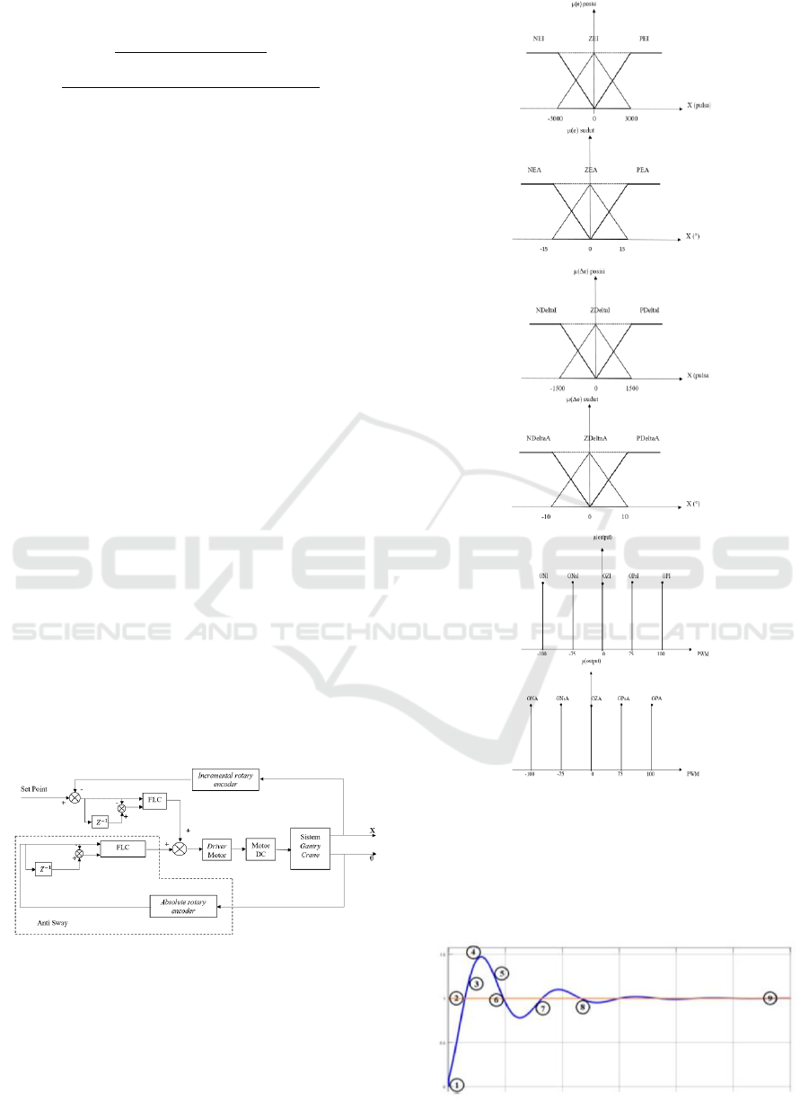
Figure 4: Diagram Block of Gantry Crane System.
There are three fuzzy sets for each FLC, namely
error (e), delta error (Δe), and PWM output values, as
shown in Figure 5. Then nine rules will be arranged
for each FLC, which can be seen in Table 1 in full.
(a)
(b)
(c)
Figure 5: Fuzzy input membership function. (a) position
and angle error (b) delta position and angle error, (c) PWM
value of the position, and angle output.
The rules used in the position FLC and angle FLC
are the same. These rules are obtained based on the
system characteristic graph shown in Figure 6 below:
Figure 6: Fuzzy input membership.
Comparison of Anti-sway Gantry Crane Control System based on PID and Fuzzy Logic Control
267

Table 1: Fuzzy logic rules position and angle.
4.2 PID
PID control (Proportional-Integral-Derivative) was a
controller with feedback that is commonly used in
industrial control systems. The PID control system
has three parameters, namely Proportional (P),
Integral (I), and Derivative (D). PID control
continuously calculated the error value or error,
which is the difference between the desired setpoint
and the measured process variable [5].
The general PID control equation could be written
as follows.
(14)
That:
Kp : Proportional gain
Ki : Integral gain
Kd : Derivative gain
e : error = Ysp - Ym
Ysp : setpoint
Ym : Process variable
t: Time
Three parameters of the PID control have outputs
with the following characteristics:
• Parameter P: proportional to the error at t at this
time.
• The parameter I: proportional to the integral from
error to t at this time, which can be interpreted
as the previous error accumulation.
• Parameter D: can be interpreted as a possible
future error.
The PID control can be represented in the form of
a block diagram in Figure 7 as follows:
Figure 7: Blok Diagram PID Control.
Figure 8: Diagram Block of PID Control System.
5 EXPERIMENT AND ANALYSIS
Anti-sway gantry crane system testing was carried out
using a rope length of 60 cm and a load of 0.5 kg.
There were two methods used, namely fuzzy logic
control and PID control.
5.1 Fuzzy Logic Control Experiment
The experiment of the whole system was done by
paying attention to two testing parameters, namely
testing without using a method and using the fuzzy
logic control method.
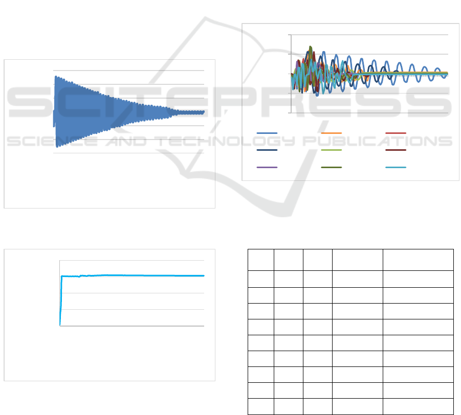
1) The Experiment Without Using Fuzzy Logic
Control
This test was carried out to determine the system
response without using control methods. The system
was given input in the form of a PWM value of 90,
which corresponds to the PWM output when the
system uses the FLC control method when the system
first runs. The setpoint of the intended position was
2500 pulses or equivalent to 37.7 cm. This test was
done by letting the crane rope swing to the point set
at an angle of 0°. The test results should be seen in the
following Figure 9 and Figure 10.
Figure 9: Angular Response Graph Without Control
Method.
-20
0
20
1,117
13,789
26,582
39,352
52,082
64,789
77,512
90,223
102,9…
115,6…
128,4…
141,2…
153,9…
Angle (
°)
Time (s)
ICONIT 2019 - International Conference on Industrial Technology
268

Figure 10: Position Response Graph Without Control
Method.
Based on Fig. 9 and Fig. 10, it could be seen that
the system without using the PID control has the
farthest deviation angle of -17.52° and takes 158,35
seconds to achieve stability. While the system’s
position without using the PID control exceeds the
setpoint specified at counter 2500. So that the PID
control method was needed so that the angle deviation
was <10° and the cart position approached the
setpoint.
2) The Experiment Using Fuzzy Logic Control
This test was conducted to determine the accuracy
of the results of the compiled algorithm. In this test,
the value of membership function input was used,
namely error € angle of the crane rope and delta error
(Δe). The negative value on error € showed the
rotation of the crane rope, which is counterclockwise.
The membership function output value has three
variations, namely the 1
st
output, the 2
nd
output, and
the 3
rd
output. The response of the angle FLC system
to each output variation was shown in the following
Figure 11.
Figure 11: Angular Response Graph with Different Fuzzy
Logic MF Outputs.
Table 2: The experiment with Different Fuzzy Logic MF
Outputs.
Based on Table 2 above, it could be seen that at
the time of the membership function (MF), the 1
st
fuzzy logic output the system could achieve stability
after 3.885 seconds and has the farthest deviation of -
8.09°. The selection of MF fuzzy logic output values
was based on the parameters of the pendulum angle
response to time, where the MF value of the 1
st
fuzzy
logic output was chosen because it requires a faster
time to achieve stability compared to other values.
The response of the position FLC system to each
output variation is shown in the following Figure 12.
Figure 12: Position Response Graph with Different Fuzzy
Logic MF Outputs.
Table 3: The experiment with Different Fuzzy Logic MF
Outputs.
MF
Output
ON
ONs
OZ
OPs
OP
Time
(s)
Ke-1
-75
-50
0
50
75
2,831
Ke-2
-150
-75
0
75
150
1,833
Ke-3
-100
-75
0
75
100
1,833
Based on Table 3 above, it could be seen that
during the membership function (MF), the 2nd and
3rd fuzzy logic output, the system could achieve
stability after 1,833 seconds. But the closest to the
setpoint (2500 pulses) was the 2nd fuzzy logic output.
0
500
1000
1500
2000
2500
3000
1,117
13,789
26,582
39,352
52,082
64,789
77,512
90,223
102,934
115,660
128,402
141,203
153,988
Position (pulsa)
Time (s)
-20
0
20
40
0,03
0,85
1,71
2,62
3,52
4,43
5,33
6,24
7,14
8,05
8,95
9,86
10,77
Angle (
°)
Time (s)
output ke-1 output ke-2
output ke-3
0
1000
2000
3000
4000
0,04
0,86
1,741
2,648
3,538
4,404
5,267
6,131
6,994
7,86
8,724
9,588
Position (pulsa)
Time (s)
output ke-1 output ke-2
output ke-3
Comparison of Anti-sway Gantry Crane Control System based on PID and Fuzzy Logic Control
269
The selection of MF fuzzy logic output values was
based on the parameters of the position of the cart
response to time, where the MF value of the 2nd fuzzy
logic output was chosen because it requires a faster
time to achieve the lowest stability and steady-state
error.
5.2 PID Control Experiment
The experiment of the whole system was carried out
by paying attention to two testing parameters, namely
testing without using a method and using the PID
control method.
1) The Experiment Without Using PID Control
This test aims to determine the angle and position
response to the time before PID control methods are
given. In this test, the setpoint for the cart position
was determined by the value of 2500 pulses. After
that, the test was carried out to see the farthest corner
deviation produced and the position of the cart when
not using the PID control method. The results of these
tests could find out how long the system reaches
stability.
Figure 13: Angular Response Graph Without PID Control
Method.
Figure 14: Position Response Graph Without PID Control
Method.
Based on Figure. 13 and Figure. 14 it could be
seen that the system without using the PID control has
the farthest deviation angle of -12.59° and takes 82
seconds to achieve stability while the system's
position without using the PID control exceeds the
setpoint specified at counter 2500. So that the PID
control method was needed so that the angle deviation
is <10° and the cart position approaches the setpoint.
2) The Experiment Using PID Control
This test aims to determine the design of the Kp,
Ki, and Kd values of the system to get the best
response so that the system can achieve setpoint and
stability. In this test, PID parameters were tested at
the angle of the pendulum and cart beam position.
The steps of this test were done by trial and error
on the system. Kp, Ki, and Kd values were given
alternately, then taking into account the pendulum
angle's response to time and cart's position to time. To
be able to find out the results of testing could be seen
in Figure 15 and Table 4.
Figure 15: Angular Response Graph with Different Kp and
Kd Outputs.
Table 4: The experiment with Different KP AND KD
Outputs.
No
Kp
Kd
Time (s)
Farthest
Deviation (°)
1.
1
1
21,8
6,69°
2.
4
1
10,9
5,98°
3.
8
1
9,2
5,98°
4.
1
4
15,2
5,63°
5.
4
4
9,9
3,75°
6.
8
4
11,1
5,63°
7.
1
8
7
4,22°
8.
4
8
9,4
7,04°
9.
8
8
8,7
4,04°
-15
-10
-5
0
5
10
15
0,00
7,69
15,44
23,27
31,10
39,17
47,05
54,61
61,75
68,72
75,70
82,68
89,66
Angle
(°)
Time (s)
0
1000
2000
3000
4000
0,00
8,27
16,71
25,27
33,62
42,43
50,75
58,81
66,36
73,91
81,46
89,03
Position (pulsa)
Time (s)
-10
-5
0
5
10
0,00
1,83
3,66
5,49
7,33
9,17
11,01
12,86
14,70
16,54
18,38
20,21
Angle (
°)
Time (s)
Kp=1 Kd=1 Kp=4 Kd=1 Kp=8 Kd=1
Kp=1 Kd=4 Kp=4 Kd=4 Kp=8 Kd=4
Kp=1 Kd=8 Kp=4 Kd=8 Kp=8 Kd=8
ICONIT 2019 - International Conference on Industrial Technology
270

Based on Table. 4 above could be seen that when
the value of Kp = 4 and the value of Kd = 4 reaches
stability after 9.9 seconds and has the furthest
deviation of 3.75°. However, when the Kp value = 1
and the Kd value = 8, the system could reach stability
after 7 seconds and has the farthest deviation angle of
4.22°. So that the selection of Kp and Kd values
following the system designed was Kp = 1 and Kp =
8. The choice of Kp and Kd values was based on the
parameters of the pendulum angle response to time,
so that the values of Kp = 1 and Kd = 8 require faster
time to achieve stability compared to other values and
have the farthest corner deviation that was not too
large. To find out the position response to time could
be seen in Figure 16 and Table 5.
Figure 16: Position Response Graph with Different Kp and
Ki Outputs.
Table 5: The experiment with Different KP AND KI
Outputs.
No
Kp
Ki
Time (s)
Position
(pulsa)
1.
0,1
0,01
14,2
5104
2.
0,01
0,01
23,8
2317
3.
0,05
0,01
7,2
2623
4.
0,05
0,1
12,8
3236
Test results in Table. V, it could be concluded that
the value of Kp = 0.05 and Ki = 0.01 could approach
the setpoint value determined by counter 2500. Even
though the value of Kp = 0.01 and Ki = 0.01 could
approach the specified setpoint value, but the time
needed by the system reaching setpoint requires a
long time, which is 23.8 seconds. So we get the value
of Kp =0.05 and Ki = 0.01 so that the system could
reach the desired position with a relatively fast time.
6 CONCLUSIONS
From the results of testing and analysis, it could be
concluded that this research was able to reduce the
sway that occurs in the operation of the prototype
gantry crane. The result showed that the sway could
decrease in two aspects. The first is the duration of
sway reduced from 158,35 to 3,885 second by fuzzy
logic and from 82 to 7 seconds by PID. The second is
maximum sway was also reduced from 17,52° to -
8,09° by fuzzy logic and from -12,59° to 4.22° by
PID.
REFERENCES
Bahri, Saeful., Permana Febry Angga, “Perancangan
Prototipe Sistem Kendali Gantry crane untuk Meredam
Ayunan Secara Realtime dengan Fuzzy Logic
Controller,” Jurnal elektrum, Vol. 14 No. 1 ISSN:
1979-5564, (2014).
Melindawati, Rosita., Agustinah Trihastuti, “Desain
Kontroler Fuzzy untuk Sistem Gantry Crane,” Jurnal
Teknik POMITS Vol.3, No1 ISSN: 2337-3539 (2301-
9271 Print), (2014).
M. A. Ahmad, A. N. K. Nasir, M. S. Najib dan H. Ishak.
“Anti-sway Techniques in Feedback Control Loop of a
Gantry Crane System.” ICIEA 2009 , (2009).
Rizki, Amelia Septiani. (2018). Perancangan Sistem
Kendali Untuk Kestabilan Pendulum Terbalik
Menggunakan Metode Logika Fuzzy. Bandung. Pp. 9-
12
M. Araki, “PID Control”, Control Systems Robotics and
Automation, Vol. 2, pp. 2-3.
Infenion technologies. Datasheet BTS7690.
Autonics. Datasheet EP50S.
0
2000
4000
6000
0,00
1,98
3,97
5,96
7,95
9,95
11,97
14,01
16,05
18,09
20,13
22,16
Counter (pulsa)
Time (s)
Kp=0.01 Ki=0.01 Kp=0.05 Ki=0.1
Kp=0.05 Ki=0.01
Comparison of Anti-sway Gantry Crane Control System based on PID and Fuzzy Logic Control
271
