
A Real Framework to Apply Collaborative Robots in Upper Limb
Rehabilitation
Lucas de Azevedo Fernandes
1 a
, Thadeu Brito
2 b
, Luis Piardi
2 c
, Jos
´
e Lima
3 d
and Paulo Leit
˜
ao
2 e
1
Universidade Tecnol
´
ogica Ferderal do Paran
´
a, Paran
´
a, Brazil
2
CeDRI - Research Centre in Digitalization and Intelligent Robotics, Portugal
3
INESC TEC - INESC Technology and Science and CeDRI -
Research Centre in Digitalization and Intelligent Robotics and Polytechnic Institute of Braganc¸a, Portugal
Keywords:
Robotics Rehabilitation, Collaborative Robots, Reinforcement Learning, Human–robot Interaction.
Abstract:
Rehabilitation is an important recovery process from dysfunctions that improves the patient’s activities of
daily living. On the other hand, collaborative robotic applications, where humans and machines can share the
same space, are increasing once it allows splitting a task between the accuracy of a robot and the ability and
flexibility of a human. This paper describes an innovative approach that uses a collaborative robot to support
the rehabilitation of the upper limb of patients, complemented by an intelligent system that learns and adapts
its behaviour according to the patient’s performance during the therapy. This intelligent system implements
the reinforcement learning algorithm, which makes the system robust and independent of the path of motion.
The validation of the proposed approach uses a UR3 collaborative robot training in a real environment. The
main control is the resistance force that the robot is able to do against the movement performed by the human
arm.
1 INTRODUCTION
According to the World Health Organization, the
number of people that live with disability had in-
creased by 17 million between 2005 and 2015. About
74% is linked to health conditions where the patient
could benefit from rehabilitation (Gimigliano and Ne-
grini, 2017). It is mainly focused on the elderly popu-
lation as a risk group of cardiovascular and respiratory
diseases. The population of the world aged 60 years
and over is set to increase from 841 million in 2013
to more than 2 billion in 2050, according to (Chatterji
et al., 2015). In this way, the rehabilitation process is
of huge importance to society.
This paper demonstrates how a collaborative robot
can help patients with non-paralysing dysfunctions of
upper limbs. The proposed system is based on the col-
laborative robot UR3 from Universal Robots
c
and on
a
https://orcid.org/0000-0001-6054-6716
b
https://orcid.org/0000-0002-5962-0517
c
https://orcid.org/0000-0003-1627-8210
d
https://orcid.org/0000-0001-7902-1207
e
https://orcid.org/0000-0002-2151-7944
the control of the force applied to the movement by
using a self control algorithm based on the Reinforce-
ment Learning (RL) approach. The UR3 end-effector
is equipped with a force sensor that provides the data
about the movement performed by the patient.
The self control algorithm is implemented in
Python to communicate with the collaborative robot.
It is noted in (Toth et al., 2005) that a long time is
wasted in the set up of the system for each patient and
exercise. This time can be decreased using the au-
tonomous control algorithm because it is adaptable to
patient needs (force) on a free trajectory, i.e., the ther-
apist may indicate any path to the patient without hav-
ing to configure the movement on the robot and, when
there is a realisation of the motion, the autonomous
algorithm gives the resistance force independently of
the exercise’s directions.
This work presents the results through the realiza-
tion of an experiment of the system with a healthy
patient. This experiment was divided in two parts:
the first considering the training only in one axis and
second in the three Cartesian axes. The data about
the movement, such as the applied force by the hu-
man arm on the UR3, the resistance provided by the
176
Fernandes, L., Brito, T., Piardi, L., Lima, J. and Leitão, P.
A Real Framework to Apply Collaborative Robots in Upper Limb Rehabilitation.
DOI: 10.5220/0009004501760183
In Proceedings of the 13th International Joint Conference on Biomedical Engineering Systems and Technologies (BIOSTEC 2020) - Volume 1: BIODEVICES, pages 176-183
ISBN: 978-989-758-398-8; ISSN: 2184-4305
Copyright
c
2022 by SCITEPRESS – Science and Technology Publications, Lda. All rights reserved

robot on the motion, the velocity and position of the
end-effector and the rewards obtained using the self
control are presented.
The rest of this paper is organized as follows. Sec-
tion 2 presents the related work on rehabilitation using
automatic devices, e.g., robots. Section 3 describes
the development of the simulation and real robot in-
terface and the algorithms to analyze the patient per-
formance and the self-control module. Section 4 dis-
cuses the obtained results both in simulation and real
robot. Finally, Section 5 presents some conclusions
regarding this problem and points out future works.
2 RELATED WORK
Industrial robotic arms are not unique to manufactur-
ing processes on a shop-floor, with the emergence of
the human-robot interaction concept demonstrated by
(Toth et al., 2004), it is possible to develop robotic
applications that exercise patients with upper limb
trauma. The effectiveness of this system and the
safety processes developed to avoid further injury to
patients are presented in (Toth et al., 2005), where it
is evident that the point of most interest in these ap-
plications is the control system.
During physical therapy movements the patient
needs a force opposite to his/her movement to have
an evolution of his/her clinical condition, (Gijbels
et al., 2011) through a mechanical spring system
(The Armeo Spring) compares different coefficients
for over weeks of treatment. With resistance to move-
ment during physical therapy, multiple sclerosis pa-
tients have achieved improvements in the treatment of
upper limb muscle strength. Other work with Armeo
Spring is shown by (Cort
´
es et al., 2014), where a
model of an upper limb integrate into Virtual Reality
(VR) is applied. The propose of work is to establish
a method to estimate the posture of the human limb
attached to the exoskeleton. The joint angle measure-
ments and the constraints of the exoskeleton are used
to estimate the human limb joint angle in VR. The
simulation was performed in the V-REP platform and
signals were measured direct from Armeo. For upper
limb rehabilitation by exoskeleton-guided movement
methods, the state of the art from (Tejima, 2001; Lo
and Xie, 2012) lists the main developments, contribu-
tions, and future research for the sector.
In recent years collaborative robotic arms have
emerged as a strong ally in human-robotics interac-
tion, whether in domestic, industrial, academic and
clinical applications. This type of robot, when em-
ployed in patient’s rehabilitation situations, requires
a certain infrastructure, described by (Malosio et al.,
2010). The system architecture that assists patients
in motor recovery consists of a central control ele-
ment, actuators, sensors, and algorithms. In this way,
collaborative robots, besides helping people with up-
per limb difficulties to perform daily tasks (Maheu
et al., 2011), can also contribute to motor rehabili-
tation when well configured.
Using a 7 Degrees of Freedom (DoF) KUKA
robot, (Papaleo et al., 2013) describes the develop-
ment of a patient-tailored system, that is, the system
is capable of adapting to patient interactions through
sensing installed in conjunction with the robot. With
this tool, it is possible to assist patients in Activities
of Daily Living (ADLs) by encouraging them to use
their residual capabilities through the process of mon-
itoring their performance, either by 3D or 2D motion.
When monitoring a patient’s performance while
executing the task, it is recommended that the sys-
tem be provided by learning by observation, ie the
system should have the Interactive Learning Control
(ILC) technique (Realmuto et al., 2016). Thus, the
implementation of the proposed system can be up-
dated during the patient’s evolution. This process is
important for the patient to have evolution during the
ever increasing rehabilitation. The usage of systems
that have to train by supervised learning is shown by
the Universal RoboTrainer project (Weigelin et al.,
2018). It is used the advantage of collaborative robots
to improve the rehabilitation of his/her patients. This
project uses a model from Universal Robot to train
disabled upper limbs, where the main idea is based on
studies that prove the effectiveness of repetitive move-
ments in the treatment of dysfunctions. Some tests
with this device have been performed in real cases.
One of them addresses the confidence in the medical
human-robot iterations, and presents the main issues
in that approach on the patient side, as signs of dis-
tress in the exercises, concern, and expectation about
the movements attached to a robot arm, and others.
The aforementioned works are fundamental for
the proposed approach in developing a skillful frame-
work to support patients in upper limb rehabilitation
with collaborative robots. Each of them demonstrates
the key points for the development of our system, thus
these points are described in more detail in future ses-
sions.
3 SYSTEM ARCHITECTURE
In order to rehabilitate patients with problems due
to ADLs, the first step was the development of the
system architecture shown in Figure 1, composed of
hardware, to unite all parts of the system and use its
A Real Framework to Apply Collaborative Robots in Upper Limb Rehabilitation
177
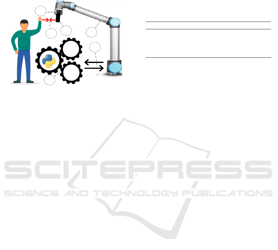
functions, together with software architecture and an
application procedure developed in python.
1
3
2
4
Sarsa
Learning
Q-
Learning
6
5
Sensor Data Force [N]
Force Resistence
7
Figure 1: System Architecture of proposed approach.
The point numbers in Figure 1 represent each part
of the system, (1) the user who interacts with the
robot by moving his arm, resulting in the applica-
tion of forces on different Cartesian axes (X, Y, Z)
acting on the robot tool. In (2) is the robot itself,
which is a collaborative manipulator. This manipu-
lator is equipped with a force-torque sensor FT-300
(3), capable of measuring force in the X, Y and Z di-
rections of the Cartesian plane. Coupled to the force
sensor (4) is a cone-shaped 3D printed tool that the
user can hold and perform movements with the robot.
This printed piece has high rigidity, able to withstand
the force exerted by the user on the robot, this itera-
tion of forces between the robot and the user is rep-
resented by (5). Then, (6) represents RL algorithms
(“Q-learning” and “SARSA Learning”) which, de-
pending on the movement performed by the human,
will adjust the resistance to movement (“force Resis-
tance”) using the data measured with the force sensor
(“Sensor Data Force (N)”) linked to the rehabilitation
manipulator. Finally, (7) indicates Modbus TCP com-
munication between the robot and the computer run-
ning the python application. The robot sends the force
data applied to all axes, which is processed by the pro-
gram, which returns the resistance force that the robot
will apply in the iteration with the user.
3.1 Mechanical Description
The developed application is composed by several
components. The manipulator robot that reacts to
the forces applied by the user refers to a Universal
Robots UR3 collaborative robot. It is a small collabo-
rative tabletop robot for light assembly tasks and au-
tomated workbench scenarios, equipped with a con-
trol box and a programming user interface. The robot
weighs 11 kg, with a payload of 3 kg, 360-degree
rotation on all wrist joints, and infinite rotation on
end joint. These unique features make UR3 a flexi-
ble, lightweight, collaborative table-top robot to work
side-by-side with humans in a safe way.
Table 1: Specifications of the FT300 force-torque sensor.
Feature Value Unit
Measure Range FX, FY, FZ +/- 300 N
Measure Range MX, MY, MZ +/- 30 N.m
Data Output Rate 100 Hz
Weight 0.3 Kg
The UR3 robot is equipped with a force-torque
sensor FT300 of 6 DoF. However, only three DoFs
were processed for this work: the force on the X ,
Y and Z axis to measure the force of human during
the procedure of interacting with the robot. Table 1
presents the specifications of this sensor. The data
FX, FY and FZ represents the measure of force in
each direction. The variables MX, MY and MZ are
the moments that can be measured.
3.2 Self Control Model Description
The robotic system has to provide force training to
help the improvement of the musculoskeletal struc-
ture. Resistance force is applied to the motion of the
patient arm. If the executed force by the human was
always constant, it would only be necessary to set a
resistance force proportional to this value to ensure
that the arm performs a higher force, fulfilling the ob-
jective. However, once the system is dynamic, some
control is necessary to set that resistance force accord-
ing to the human arm force.
Another rehabilitation systems found in literature
develop their control in other ways, as presented as an
example in (Toth et al., 2005). In most cases, larger
periods (time) are wasted to set up the system to each
patient. Therefore, to improve the usability and facil-
ity was implemented a self-control based on the RL
technique, and it is a method in which the robotic sys-
tem uses information gathered from the environment
to learn the best action to take.
When the system is active, the robotic arm can
recognize the force of the patient and change its joint
torque values, making them responsible, in real-time,
by itself and adaptable to any patient. The premise of
the system is to work with the patients that are capable
of performing some upper limb motion, therefore the
biofeedback will be the force performed in this move-
ment. No pre-programmed path planning is required
on the robot’s side, but the therapists shall indicate to
the patient which are the motions for that treatment
section.
BIODEVICES 2020 - 13th International Conference on Biomedical Electronics and Devices
178

The RL algorithm used to built the self control
is called SARSA. The concept and functionality of
this control algorithm are best explained in (Sutton
and Barto, 2018; Lewis and Vrabie, 2009; Wiering
and Van Otterlo, 2012). The SARSA algorithm is
constructed to make a decision in a dynamic process
and to adapt the next choice to the environment. It
is worth remembering that the RL systems are used
to solve the Markov Decision Process (MDP) (Sutton
and Barto, 2018).
The MDP is a framework that guides a decision in
a dynamic process. Explaining quickly the environ-
ment on an MDP is separated in states and actions.
The states represent each system setting (this setting
can be the value of position, speed, angle, force, or
otherwise). Actions are the dynamic process that
drives the system from one specific state to another
(this dynamic process can be understood as chang-
ing the variables represented by states). Applied to
the rehabilitation problem, the states to be understood
are all forces performed by the human arm. The ac-
tions are represented by the possible decisions that the
system can make. Working with the resistance force,
the decisions are: increase the force performed on the
end-effector, decrease or hold the same variable.
The goal of self-control is to choose the best deci-
sion based on the system’s current state. However, as
this behavior is not known at first, the method of trial-
and-error is performed. Initially, the system starts in
some state s
x
, makes a decision (some action a
x
is per-
formed), goes to another different state s
y
, and based
on this new state, chooses the new action a
y
. When
the system act in the environment some feedback sig-
nal is collected. This value is used to evaluate the
action a
x
in the certain state s
x
. So, if the action re-
sults in an expected state (considered positive for the
system) the algorithm awards a positive reward r
x
to
the set “previous state - action - next state”, else the
reward is negative to the same set. The attribution of
positive rewards is linked, in this case, to the resis-
tance force made by the robot that guides the patient
to perform the expected arm strength in that physio-
therapy session.
The rewards are used to calculate the Q-matrix,
which relates the states with the actions. For SARSA
technique the Q-matrix is updated using the Equation
1. Note that on the updating are used: s
x
, a
x
, r
x
, s
y
,
and a
y
. As the system uses the pair (s
y
,a
y
) is possible
to evaluate if the current action a
x
will generate the
next better action a
y
.
Q(s
x
,a
x
) ← Q(s
x
,a
x
) + α(
r
x
+ γQ(s
y
,a
y
) − Q(s
x
,a
x
)
)
(1)
Therefore, if an action a
x
in the state s
x
gets many
positive rewards, the Q-matrix value corresponding to
this pair (state, action) will be greater than the other
actions for the same state. Therefore, this pair (s
x
,a
x
)
will always be chosen in further similar decisions.
The constants α and γ are called learning rates and
both are values in the range [0,1]. These values are
used because the system could perform a pair (s
x
,a
x
)
that results in a positive reward, but it is not a bet-
ter solution. Thus, to ensure that values that appear
correct do not increase very quickly, the system uses
these variables as a discount. There is no method for
calculating these values, but if they are too small the
system will take longer to converge, and if they are
too close to 1 the system will be more likely to get
stuck at a local maximum.
An essential concept used in this approach are the
episodes (the set of iterations that comprehend a mo-
tion of the human arm in period of time). In other
words, a single episode corresponds to all the mea-
surements performed by the robot during 0.2 seconds
(15 iterations).
To ensure that the system will always measure a
real value without a possible measured noise (due to
the changing movement direction), an average mea-
surement based on the episode is configured. For this
reason, each measurement presented on the Section 4
represents a set of 15 interactions within the environ-
ment.
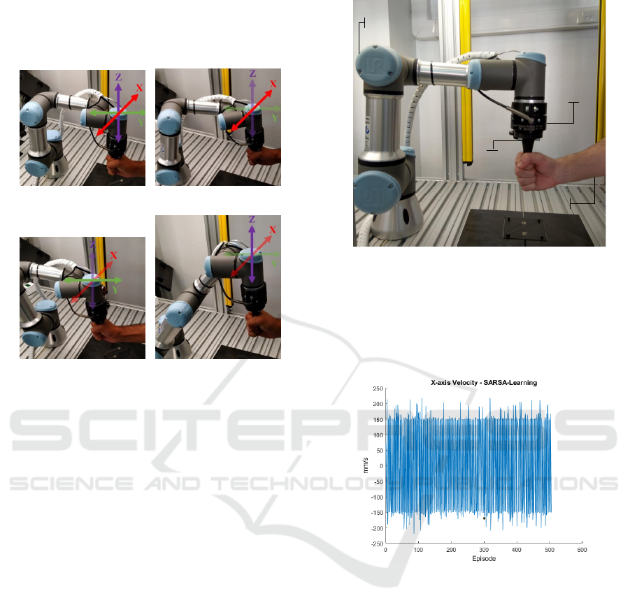
3.3 Real Robot Interaction
The interaction between the human and the robot will
be divided into two moments. At first, it was re-
quested to the patient to move the robot only along the
x-axis. To help the patient to accomplish the proposed
movement, the UR3 was configured also to move in
the same axis that is represented by the red arrow in
Figure 2b. When the patient starts the motion, the
sensor starts measuring and this data is used to feed
the RL technique. After that, it was requested for the
patient to move the robot in any direction, in other
words, the human can move the robot along the three
Cartesian axes that are displayed in Figures 2b, 2c and
2d. This makes the decision of the system much more
complex because the robot should deliver the resis-
tance force in three axes and none of them can inter-
fere in another.
Note that on both stages of the experiment the
patient tried to execute a movement with a constant
velocity. The robot at both moments is set to never
change the angle of the end-effector as this could
cause calculation errors on the side of the control al-
gorithm. Another set up in the UR3 is that all the mo-
A Real Framework to Apply Collaborative Robots in Upper Limb Rehabilitation
179
tions start from a home position, exemplified in Fig-
ure 2a. Before the movement begins, the force sensor
attached to the robot is re-calibrated to avoid errors in
the measurements.
(a) Home position. (b) Axis X.
(c) Axis Y. (d) Axis Z
Figure 2: Images that show the motions along the three
Cartesian axes.
4 RESULTS
The results are measured using the RL algorithm as
the self-control model applied in the UR3 to training
with a healthy person. The patient has 23 years old,
1,92 meters, and 0.81 meters of arm’s length. The set
up of the experiment is: the individual stands in front
of the robot, grabs the UR3’s end-effector as shown
by Figure 3, and moves the robot along a path stipu-
lated by the experiment therapist.
The experiment goal is to train the algorithm to
provide a resistance force according to the patient
needs in both cases. Therefore, the results presented
in this section will be divided into two parts, the one
axis, and the three axes experiment, respectively.
4.1 The One Axis Experiment
This part refers to the first iteration of the intelli-
gent system with the patient arm. The system records
the values of the movement provided by sensors and
robots. The first variable shown in Figure 4 is the ve-
locity of the UR3’s end-effector. It is expected that
the velocity stands around value and it seems to hap-
pen during all training for the two algorithms. The
value of this velocity is 150 mm/s and the variation
COLABORATIVE
ROBOT
FORCE TORQUE
SENSOR
3D PRINTED
TOOL
HUMAN IN
REHABILITATION
Figure 3: Force training with the patient.
between the negative and positive value occurs due to
the changing of direction of movement. It is also no-
ticed some overtaking in the velocity’s curve. This
may occur due to measurement errors or the motion
changing.
Figure 4: Recorded velocity on the movement.
Another variable is the end-effector position. As
the behavior is independent of the trajectory, this
curve is not always well defined and it is presented
in Figure 5.
Even disregarding the trajectory, some movement
patterns can be noticed due to the UR3 characteristics.
This fact is explained by the curve generated in Figure
4 resembling the resistance force values provided by
the UR3 manual. To analyze how this value changes
and when this happens, the Figure 6 shows the com-
parison between the curves. Note that it is presented
a set of episodes to facilitate the reading of the data.
The behavior expected is again noticed. The po-
sition curve represents the force direction measured
by sensor. This means that the resistance force ap-
plied by the UR3 robot should be the same behavior,
but on the opposite way. The UR3’s force showed in
BIODEVICES 2020 - 13th International Conference on Biomedical Electronics and Devices
180
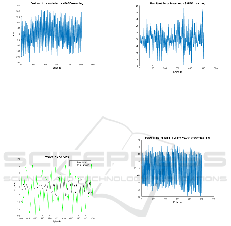
Figure 5: Recorded position on the movement.
Figure 6 is calculated by the self-control using as an
input the measured resultant force by the sensor. It is
also considered as a goal of the system, that the same
variable is around the value of 25 N, inside a proposed
range (20 N - 40 N). The system cannot guarantee that
the forces are always inside the proposed range, how-
ever, most times has to seek this target. The Figure 7
shows this data to the entire training. Notice that the
data represents the force measured in the three axes
(XY Z). Even that motion is only in one axis, there are
reading forces in all axes and these variables should
be considered.
Figure 6: Comparison between position and resistance
force.
Figure 7 presents many values that exceed the
40 N. Some of these values can be considering that
the patient can execute this force for a short period
(time). However, this value not always represents re-
ality. Even with the technique used to mitigate the
reading errors, some of them were detected, princi-
pally when the patient changes the direction of the
movement. Therefore, the analysis must be done con-
sidering the average value of the force, which seems
to be around 28 N, and this is acceptable behavior.
This overtakes are also a result of the force applied
in the other axes recorded by the sensor. Thus, if the
forces on the other directions were disregarded, the
force should perform better.
Figure 7: The measured resultant force by the sensor.
Figure 8 presents the force for the measurements
about the x-axis. The value of the force depends on
the direction of the movement. So, the reading of this
variable should only be considered the value mod-
ule. However, this curve also shows to the reader that
the systems choose the next resistance force indepen-
dently of the direction, promoting an almost constant
variation in the x-axis force.
Figure 8: The measured force by the sensor on the x-axis.
The system seeks for actions (inside the proposed
set of actions) that are correct just for some specific
situations. It is expected that the self-control chooses
these correct actions to get the rewards and at the end
of training the negative be smaller than the positive.
This objective is reached and the Figure 9 shows a
comparison between the number of positive (+1) and
negative (-1) rewards assigned. The number of posi-
tive rewards, where the system recorded a human arm
force inside the proposed range, is at least two times
larger than the negative rewards.
The goal pursued was successfully achieved, pre-
cisely because the force of the human arm remained
around the force established during almost all train-
ing. However, it is not clear what is the better resis-
tance force that the robot should deliver to the patient
in each episode. The data recorded on the selected
force shows exactly this situation, as stressed in Fig-
A Real Framework to Apply Collaborative Robots in Upper Limb Rehabilitation
181
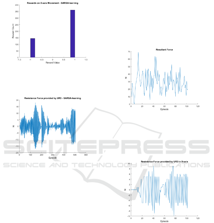
Figure 9: Rewards assigned by the SARSA algorithm.
ure 10. Nevertheless is possible to analyze that the
robot didn’t learn the better force, but the learning was
the best moments to increase or decrease the force.
Figure 10: The UR3’s applied force.
It was noticed that empirically an UR3 force of
6 N is capable to ensure that the arm will execute
a force close to expected, but this value depends on
the position of the patient relative to the robot. Thus,
sometimes a smaller or higher resistance force is re-
quired to accomplish the goals. As the system is dy-
namic and complex, 500 interactions were not enough
to make the system to fit optimally, but it is possible to
verify that this same number of episodes was enough
for the robot to have the expected behavior.
4.2 The Three Axes Experiment
In this experiment stage, the patient was free to move
the UR3’s end-effector to any possible place, respect-
ing the limitation of the robot. Before the training
starts, the sensor was again re-calibrated due to the
same reasons for the first part. As the algorithm works
with a more complex system and should provide the
resistance force in the three axes, some modifications
need to be made. Therefore, the self-control was built
considering the increment of the resistance force sep-
arately. The reward was obtained to the entire system,
i.e., only one Q-matrix was responsible to capt the in-
formation, but the choices to increase or decrease was
executed separately considering the values of force on
some axes.
The measured resultant force is presented in Fig-
ure 11. This force is too large in the first episode,
but in the sequence, it seems to normalize nearby an
acceptable value.
Figure 11: Resultant force measured by the sensor.
The same happens for the robot force. Figure 12
shows this force for the x-axis. The force seems to
remain nearby value of 4 N. Similar behavior is noted
in the other two axes. It is also important to remember
that the learning is linked to the actions of increasing,
decreasing or maintaining the force.
Figure 12: robot force in X-axis.
Even using self-control, the learning was not per-
fectly suitable for this problem. The algorithm grants
the rewards based on the resultant force and this en-
sures that the system always will search for a value
inside of the range specified. However, as only one
Q-matrix controls the three axes, the value of an axis
interferes with each another. Thus the system did not
learn the better force for the motion in each axis, but
learn some range of values that can be used in the
three axes, independently to seek the desired resultant
force.
BIODEVICES 2020 - 13th International Conference on Biomedical Electronics and Devices
182

A solution for this problem is to create an algo-
rithm that is capable to perform a decision based on
the robot force on three axes, the actions and the po-
sition on three axes. This implies a Q-matrix with ten
dimensions. Another solution is to implement three
tri-dimensional Q-matrix, each one evaluating each
axis and another that will evaluate the movement in
terms of the resultant force.
5 CONCLUSIONS
The rehabilitation is actually of main importance for
the society. The use of a collaborative robot to per-
form this task could be a tool to help the therapist to
treat his patients. This paper addressed a UR3 col-
laborative robot as an assistant to the rehabilitation
process. The main contribution of this work is the
development of a system that brings together emerg-
ing technologies to improve the human-robot relation-
ship. Besides, the insertion of a self control module
removes the need for the robot’s path planning and its
configuration to each patient. Since there is a simula-
tion environment for the proposed system, it possible
to identify any failure and make adjustments, prin-
cipally when this technology is applied together to
human touch. The reinforcement learning was used
to adjust parameters and adapt the movements to the
patient on-the-fly. Once the simulation is tuned, the
UR3 robot is used to test the SARSA algorithm in a
real environment. It allows validating the proposed
system. As future work, more data can be acquired
from the patient to adapt the robot movements more
truly.
REFERENCES
Chatterji, S., Byles, J., Cutler, D., Seeman, T., and Verdes,
E. (2015). Health, functioning, and disability in older
adults—present status and future implications. The
lancet, 385(9967):563–575.
Cort
´
es, C., Ardanza, A., Molina-Rueda, F., Cuesta-G
´
omez,
A., Unzueta, L., Epelde, G., Ruiz, O. E., De Mauro,
A., and Florez, J. (2014). Upper limb posture estima-
tion in robotic and virtual reality-based rehabilitation.
BioMed research international, 2014.
Gijbels, D., Lamers, I., Kerkhofs, L., Alders, G., Knippen-
berg, E., and Feys, P. (2011). The armeo spring as
training tool to improve upper limb functionality in
multiple sclerosis: a pilot study. Journal of neuro-
engineering and rehabilitation, 8(1):5.
Gimigliano, F. and Negrini, S. (2017). The world health or-
ganization “rehabilitation 2030–a call for action”. Eur
J Phys Rehabil Med, 53(2):155–168.
Lewis, F. L. and Vrabie, D. (2009). Reinforcement learning
and adaptive dynamic programming for feedback con-
trol. IEEE circuits and systems magazine, 9(3):32–50.
Lo, H. S. and Xie, S. Q. (2012). Exoskeleton robots
for upper-limb rehabilitation: State of the art and
future prospects. Medical engineering & physics,
34(3):261–268.
Maheu, V., Archambault, P. S., Frappier, J., and Routhier,
F. (2011). Evaluation of the jaco robotic arm: Clinico-
economic study for powered wheelchair users with
upper-extremity disabilities. In 2011 IEEE Interna-
tional Conference on Rehabilitation Robotics, pages
1–5.
Malosio, M., Pedrocchi, N., and Tosatti, L. M. (2010).
Robot-assisted upper-limb rehabilitation platform. In
2010 5th ACM/IEEE International Conference on
Human-Robot Interaction (HRI), pages 115–116.
Papaleo, E., Zollo, L., Spedaliere, L., and Guglielmelli, E.
(2013). Patient-tailored adaptive robotic system for
upper-limb rehabilitation. In 2013 IEEE International
Conference on Robotics and Automation, pages 3860–
3865. IEEE.
Realmuto, J., Warrier, R. B., and Devasia, S. (2016). It-
erative learning control for human-robot collaborative
output tracking. In 2016 12th IEEE/ASME Interna-
tional Conference on Mechatronic and Embedded Sys-
tems and Applications (MESA), pages 1–6.
Sutton, R. S. and Barto, A. G. (2018). Reinforcement learn-
ing: An introduction. MIT press.
Tejima, N. (2001). Rehabilitation robotics: a review. Ad-
vanced Robotics, 14(7):551–564.
Toth, A., Arz, G., Fazekas, G., Bratanov, D., and Zlatov, N.
(2004). 25 Post Stroke Shoulder-Elbow Physiother-
apy with Industrial Robots, pages 391–411. Springer
Berlin Heidelberg, Berlin, Heidelberg.
Toth, A., Fazekas, G., Arz, G., Jurak, M., and Horvath,
M. (2005). Passive robotic movement therapy of the
spastic hemiparetic arm with reharob: report of the
first clinical test and the follow-up system improve-
ment. In 9th International Conference on Rehabili-
tation Robotics, 2005. ICORR 2005., pages 127–130.
IEEE.
Weigelin, B. C., Mathiesen, M., Nielsen, C., Fischer, K.,
and Nielsen, J. (2018). Trust in medical human-robot
interactions based on kinesthetic guidance. In 2018
27th IEEE International Symposium on Robot and
Human Interactive Communication (RO-MAN), pages
901–908. IEEE.
Wiering, M. and Van Otterlo, M. (2012). Reinforcement
learning. Adaptation, learning, and optimization,
12:3.
A Real Framework to Apply Collaborative Robots in Upper Limb Rehabilitation
183
