
Analyzing Software Application Integration into Evolving Enterprise
Business Processes using Process Architectures
Zia Babar
1
and Eric Yu
1,2
1
Faculty of Information, University of Toronto, Toronto, Canada
2
Department of Computer Science, University of Toronto, Toronto, Canada
Keywords: Enterprise Modelling, Enterprise Architecture, Systems Analysis and Design, Business Process Management.
Abstract: Many organizations face frequent, ongoing challenges as they attempt to integrate software applications into
their business processes, particularly as enterprises continuously evolve, resulting in shifting requirements for
these applications. The hiBPM framework supports modelling multiple interconnected processes involved in
the integration of software applications into enterprise business processes so that alternative process-level
configurations are compared and analysed. To support the evolving design capabilities and flexibilities of
process execution, we elaborate on “Design-Use” and “Plan-Execute” relationships between processes.
Design-Use relationships represent the exchange of a tool, capability or artifact that can be used repeatedly
by other enterprise business processes for attaining some process or enterprise objectives. Plan-Execute
relationships represent the exchange of information than enables process activities execution to accomplish
enterprise objectives while simultaneously reducing the space of possible process execution possibilities. We
applied the hiBPM framework at a large retail organization to illustrate how the organization could better
integrate data analytics applications into their existing business and IT processes.
1 INTRODUCTION
Enterprise architecture modeling techniques need to
be extended to visualize and reason about the
complexities involved in the design of enterprise
software systems and business processes, while
considering enterprise requirements for ongoing
change and transformation. Software that integrate
into these processes would need to adapt and
accommodate evolving process reconfigurations.
However, the enterprises in which these software are
used are themselves undergoing change, resulting in
continuous business process redesigns (Dumas, La
Rosa, Mendling, and Reijers, 2018). Enterprise
architects need to consider the evolving bidirectional
dependencies between the design of these software,
and the processes in which these software are used.
In this paper, we use the domain of enterprise data
analytics to illustrate the complexities of designing
software systems and associated processes while
adhering to changing enterprise objectives. The
findings presented are the result of a case study done
at a large retail organization. The case study covered
multiple business processes and IT processes in the
sales forecasting and promotion management area.
The first part of the case study was modeling and
analysing a set of interconnected business, IT and
software processes. This required analysing different
possible design configurations of integrating a
software solution into these processes while
considering design trade-offs. Enterprise processes
were subject to evolving requirements, with the
processes themselves changing to support such a data
analytics application, in the form of reconfigurations
to software processes that develop the solution, the IT
processes that provide the necessary data that help
with training the solution, and finally the business
process where the solution was used.
The second part of the case study was
contributing to the application design. The design of
the data analytics application that integrates into the
business processes needed to accommodate existing
business process design and the expected usage of the
software. Software applications that integrate into
these processes would thus need to adapt and
accommodate these process reconfigurations.
Conversely, the application itself required redesigns
to evolve to a state where it could be considered
optimal as initial designs may not be entirely
reflective of inherent sociotechnical challenges.
778
Babar, Z. and Yu, E.
Analyzing Software Application Integration into Evolving Enterprise Business Processes using Process Architectures.
DOI: 10.5220/0009422107780786
In Proceedings of the 22nd International Conference on Enterprise Information Systems (ICEIS 2020) - Volume 2, pages 778-786
ISBN: 978-989-758-423-7
Copyright
c
2020 by SCITEPRESS – Science and Technology Publications, Lda. All rights reserved

2 THE hiBPM FRAMEWORK
It is not sufficient to redesign individual business
processes for optimization or supporting enterprise
transformation. Several processes across the
enterprise need to be collectively studied to see how
they can help attain the enterprise's functional and
non-functional objectives. Such a collection of
processes is commonly referred to as a process
architecture (Dumas, La Rosa, Mendling, and Reijers,
2018). Enterprise models of process architecture (PA)
depict relationships between multiple business
processes that exist in a domain while abstracting
away from process-level details. These details are not
necessary as the purpose of a PA is not on how to
implement these processes, but rather how to design
the collection of processes.
The hiBPM framework (Yu, Lapouchnian, and
Deng, 2013) provides the ability to express different
design configurations of a PA. The intention is to
consider enterprise processes - business, IT, software
or otherwise – collectively and understand the design
trade-offs of moving process activities between them.
Alternative designs are, therefore, different ways of
respectively configuring the PA. The framework
provides notations that allow relevant architectural
properties to be analysed, for contrasting among
alternative PA design options can exist at variation
points within the PA.
hiBPM comprises of several constructs. Process
Element is a fundamental activity unit that produces
some output or outcome — repositioning a process
element within a PA results in variable behaviour and
characteristics to support transformation objectives.
Process Stages (or just “stages”) are collections of
process elements that are to be executed collectively
as part of the same execution cycle. Structuring of
stages is done so that they accomplish some
enterprise functionality. Executing a process element
can either be done before or after other process
elements. Postponing a process element provides the
benefit of executing it with the latest context while
advancing a process element reduces process
execution complexity, uncertainty and cost. The
hiBPM framework is discussed in more detail in (Yu,
Lapouchnian, and Deng, 2013).
The contribution of this paper is two fold. Firstly
it adds to the relationships constructs in the hiBPM
framework to better express the design and plan
relationships that exist between multiple processes.
Secondly, this extended hiBPM framework was then
applied to the enterprise under study to determine an
optimum design for integrating a data analytics
application to existing and evoling processes.
3 ENTERPRISE AGILITY
THROUGH FLEXIBLE
PLANNING AND EVOLVING
DESIGNS
3.1 Design-use Relationships
Business process execution can result in the creation
of a tool, capability or artifact that can be used
repeatedly by other enterprise business processes for
attaining some process or enterprise objective. These
are called designs in the hiBPM framework. In the
case of software applications, components are designs
built by different software processes, which are then
used during the execution of the business (or another
software) process. The hiBPM model is thus able to
capture the relationship between both sides, i.e. where
the designs are produced and where they are used.
Through Design-Use (D-U) relationships, we show
locations at which a software component integrates
into business processes. This is useful as enterprise
architects can ensure the fulfilment of process and
data dependencies at or before that point. D-U
relationships only exist if the design is used in a
downstream, immediate stage. Through, D-U
relationships, we can analyse changes to in
capabilities of continuously evolving systems. The
assumption is that the design stage will not be
executed just once to produce a tool or a capability.
Instead, driven by changing business needs, external
environments, and the feedback from the use of the
current version of the tool, the design stage can be re-
executed when appropriate. This produces new
versions of the capability, thus evolving the enterprise
and its systems.
Figure 1: Design-Use relationships in the hiBPM Model.
In Figure 1, we show a simplified hiBPM model
with two stages from the case study, each of which
has multiple process elements. The stage
Develop
Analytical Model
is responsible for creating the
designed artifact (i.e. Analytical Model), and
Perform Weekly Analysis is responsible for
(repeatedly) using the designed artifact. Here, the
Analytical Model is a design that is used by another
Analyzing Software Application Integration into Evolving Enterprise Business Processes using Process Architectures
779
downstream stage. Thus, a D-U relationship exists
between these stages, with the stage creating the
artifact called the design stage and the one using the
artifact called the use stage (with a “U” annotation
representing the using of a design in its execution).
A motivation for such a process relationship is
abstraction, i.e. the user does not need to have
detailed knowledge of how the design is built to use
it. Being able to use the design repeatedly enables
automation of process execution, which helps in
reducing the time and cost of process execution.
These are essential factors when designing the hiBPM
model for non-functional requirements. In D-U
relationships, we consider associations between how
the designs are built and the usage of the artifact. This
not only allows a contemplation on how designs are
developed but also how they are integrated and used
in a business process; thus, product innovation and
process innovation can be considered simultaneously.
We discuss this further in Section 4.
3.2 Evolving Design Capabilities
D-U relationships support the identification and
analysis of flexible design variations of the tool or
capability. Generally, the tool or capability produced
is considered rigid in the sense that it cannot be
modified during usage. However, evolving
enterprises require flexible designs whose usage can
vary considerably, resulting in different business
outcomes. These designs are considered as evolvable
objects, which can be easily be redesigned at usage
time to accommodate changes in external
environments, and business or system requirements.
Here a focus is on the flexibility of the tool/capability
produced in the design stage. The more single-
purpose (less flexible) the tool is, the simpler it is to
use and the more optimized it can be, particularly for
automating the execution of stages. For a more
flexible design (for usage-time modifiability of the
design), the design complexity may increase resulting
in additional process overhead.
In D-U relationships, process elements are placed
in the design stage or a use stage. Positioning a
process element in the design stage leads to increased
artifact sophistication (through greater design)
whereas placing the process element in the usage
stage results in greater run-time customizability of the
artifact (through manual control of a simpler design).
Tools are flexible and specific aspects can be left
unbound while providing for choices left for the user
to bind as user needs may not be known a priori. In
Figure 2, we show how D-U variability is attained by
positioning a process element on the design side or
the usage side of a process, i.e., whether the process
element is invoked as part of a design process, or is
invoked during the usage of that artifact, tool, or
capability that is the outcome of the design.
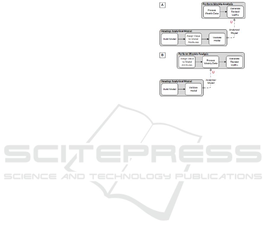
Figure 2: Evolving capabilities through partial designs.
In Figure 2(A), the use of the Analytical Model is
shown to be fully automated to simplify the process
of using the
Analytical Model to perform weekly
forecast analysis; here the design and build of the
Analytical Model takes on more functionality, thus
increasing the level of automation in the use stage.
Conversely, having a partially designed
Analytical
Model
allows for customizing the usage to fit
particular needs, in this case being able to change
various model attributes (or the values assigned to
them) to ensure that the accuracy of the revised uplifts
is improved. For this, Figure 2(B) shows a partial
design that is used during the
Perform Weekly
Analysis
stage. Reducing process elements in, or
moving process elements across the design stage to
the usage stage reduces the level of automation
available and increases the level of customizability of
the tool since the decision is no longer built into the
tool and can be changed at use.
3.3 Plan-execute Relationships
A plan provides information for the execution of
process activities to accomplish enterprise functional
and non-functional goals while simultaneously
reducing the space of possible process execution
possibilities, as there may be several possibilities to
attain these enterprise goals. A plan is the output of
the planning stage and can be an instruction set, an
arrangement of actions, or a set of specifications that
describes the method, means and constraints of
executing the plan. Downstream stages need to be
aware of the information as codified in the plan in
ICEIS 2020 - 22nd International Conference on Enterprise Information Systems
780

order to ensure proper execution. The relationship
between the planning stage and the execution stage is
called Plan-Execute (P-E). In our case study, there
was a need to have modifiable behaviour of process
execution, as and when the situation demands.
Processes may produce plans that are then executed
by downstream processes to induce some change in
the overall hiBPM model or result in some
behavioural change in the business process execution.
Through P-E relationships, hiBPM can capture the
relationship between both sides, i.e. where the plans
are devised and where they are executed.
Figure 3: Plan-Execute relationships in the hiBPM Model.
Figure 3 shows a P-E relationship between two
stages, Plan for Analytical Model that provides
instructions on how to go about with the building of
an
Analytical Model, and Develop Analytical Model
where the provided plan is executed to build the
actual model. A P-E relationship is denoted by an “X”
annotation, which is placed on the side of the process
stage that executes the plan. The
Plan for Analytical
Model
stage determines the purpose of this model,
including the attributes contained within. These are
codified as a plan that is executed by a downstream
stage during its execution.
A primary motivation for such a process
relationship is to identify two distinct segments, each
with their characteristics, with one performing
planning, whereas the other executing the plan. Both
achieve some upper-level business objective that
requires a conceptualization of both plans and execute
process segments. Data flow relationships between
two stages can be considered as a P-E relationship if
the data flow transfers a plan that is immediately
executed by a downstream stage.
3.4 Flexibility of Process Execution
P-E relationships support the identification and
analysis of variations of the completeness of plans
produced. A primary focus is on analysing the degree
of planning in the planning stage, or the degree to
which the planning can be deferred to the execution
stage, to achieve the desired level of flexibility in an
organization. A process element can move from an
execution stage to a planning stage (and vice versa)
based on their contribution to the relevant non-
functional objective. Such movements create
variations in the P-E behaviour and allow for either
increased pre-planning (by moving a process element
to the planning stage) or shifting more responsibility
to the execution side (by moving a process element to
the execution stage).
A plan produced by a stage either fully specifies
or partially constrains the behaviour of the subsequent
stages. We refer to the former as complete plans and
the latter as partial plans. For example, in
Plan for
Analytical Model, the plan on how to build the model
can be fully elaborated or certain design-decisions
(such as the attribute values to use) left for later
determining. Locking attribute values is helpful when
there is no uncertainty when building the model, and
the same instantiation would be repeatedly required.
Conversely, leaving these attributes open is beneficial
when a template is used across different settings and
custom values provided during the building process.
Both of these alternatives are shown below.
Figure 4: Execution flexibility through partial planning.
Complete or partial plans are considered based on
the need of downstream stages. E.g. complete plans
may be produced on a per-instance basis, fully
customized for the needs of a particular process
instance and therefore to be executed just once.
Alternatively, partial plans may be general enough
that downstream execution stages have the flexibility
of adjusting them at execution time through binding
different execution-stage decisions. Decreasing plan
completeness increases flexibility and ability to
handle change when executing the plan. It allows
separating stable and volatile portions of
specifications. At the same time, this puts pressure on
the execution stage to monitor for change (which
might incur data collection and processing costs) and
Analyzing Software Application Integration into Evolving Enterprise Business Processes using Process Architectures
781

to complete the partial specification provided to it by
the planning stage based on the current context.
4 ENTERPRISE AGILITY
THROUGH FLEXIBLE
PLANNING AND EVOLVING
DESIGNS
Software systems, artifacts or tools need to be
designed for automation and re-usability. In practical
terms, such software architecture designs are
produced through well-defined interfaces, class
structures and hierarchies, and code components,
frameworks and libraries. While such software can be
designed in a manner that allows for reusability by
other software systems or users, crucial design
decisions need to be made regarding their
deployability and usage over a range of conditions
and settings. On the other hand, plans can be used to
inform and guide the execution of processes that use
software systems and tools. Through the collective
use of D-U and P-E relationships, we can provide the
ability to express and analyze these situations.
The D-U relationship does not indicate how to
have flexible execution at runtime, and this needs to
be shown separately as a P-E relationship. Using both
P-E and D-U relationships can allow for introducing
flexible design capabilities, simultaneously helping
understand when and how to introduce change in
execution behaviour. Here, a plan can influence how
a design is used by providing varying instructional
input to the stage that is using the design. In Figure 5,
we show how both relationships come together to
bring about both flexible planning and evolving
design capabilities in the enterprise.
Figure 5: hiBPM model for flexible plans and evolving
designs.
Introducing D-U and P-E relationships to the
hiBPM model may require additional changes,
particularly when supporting evolving design
capabilities. Representations of design, development
or other tool acquisition processes need to be
integrated to allow modeling of evolving capabilities
available while supporting continuous design. For
instance, being able to evaluate tool redesign cycles
relative to other changes in the enterprise allows the
identification of rigidities in organizations and the
evaluations of cost-effective ways to remove those.
Often, these necessitate the addition of supporting
stages that surround the locations at which the D-U
and P-E relationship are introduced. These are done
to ensure that the use stage or the execution stage has
all the requirements available to process design or
plans. For example, in Figure 5,
Plan for Analytical
Model
stage provides the necessary information for
the execution of the
Develop Analytical Model stage,
specifically the need for having an
Analytical Model
Plan
that is used during the execution stage.
There is an essential distinction in how designs
and plans are conceptualized in hiBPM. Designs are
considered to be pre-built black box artifacts that can
adopt different forms; they may be physical objects,
a digitized entity or even be informational. The
designs are black-boxes as a user should not care
(neither is informed) about the internal structure of a
design artifact or how it is built, and is only concerned
about whether the objectives are achieved when
invoked during usage. Contrary to this, a planning
stage devises the plan irrespective of how the
execution stage will execute it. The execution stage is
aware of the plan internals to interpret and best
execute the plan based on requirements and trade-off
analysis that can be done as part of its execution.
Various design options for the data analytics
application were considered during this study. hiBPM
models were used to differentiate between different
design options. The aim was that despite the
uncertainty in the form of the final data analytics
application, the organization’s processes should not
have to substantially change from what was designed
and determined here. Through the D-U and P-E
relationships, we were able to show what designs
were needed, and what plans were to be devised, to
support different possible application solutions.
4.1 Fully Automated Forecasting
The research team identified additional possible
solution configurations during the deliberation
process. Analyzing and adjusting the product sales
number once a week causes forecasting inaccurances
for the days within this forecasting period. However,
this is presently preferred as performing the same
ICEIS 2020 - 22nd International Conference on Enterprise Information Systems
782

operational on a daily basis is impractical, time-
consuming and computationally intensive.
In Figure 5, we showed how the sales forecast was
either positively or negatively adjusted in the
Perform Weekly Analysis by involved users after a
round of sales review and using their collective
experience. This adjustment was an automated
activity performed by software that automatically
generated revised uplifts. However, this is a simplistic
solution and merely mimics the current process
behaviour at the enterprise (albeit automating critical
aspects of it). The
Analytical Model designed adjusts
uplifts on a weekly level without considering the
daily variations in forecasted sales and actual sales. A
more sophisticated solution would have both daily
and weekly forecasted sales adjustments, with the
process planner adjusting the workflow as needed.
The solution would require a redesign of both the
analytical model and the processes where the
analytical model is used. The redesign trigger is the
Monitor Context stage, which actively determines if
the forecasted sales and actual sales numbers are
sufficiently different daily. Once it detects that the
deviation is statistically significant, it would initiate a
redesign by calling the
Plan for Analytical Model and
Plan for Process Config stages with the appropriate
data. Note, this reconfiguration of both the Analytical
Model
and the hiBPM model is not done on a per-
instance level. Rather it is meant to be an infrequently
reconfiguration when there have been sufficient
changes in context to warrant such an expensive
operation. The hiBPM model snippet showing the
new PA configuration is shown in Figure 6.
Figure 6: Full automation of the forecast sales process.
Both these processes accept the Filtered Context
and initiate replanning activities that result in a
redesign plan -
Analytical Model Plan in the case of
Plan for Analytical Model and Process Reconfig
Plan
in the case of Plan for Process Config. As
before, the Develop Analytical Model takes the
Analytical Model Plan, along with accepting a Model
Catalogue
consisting of analytical model design
patterns, to produce an Analytical Model. This model
is capable of generating uplifts either at a daily or
weekly level. Similarly, the
Plan for Process Config
generates a Process Reconfig Plan that is then
processed by the Execute Process Config Plan to
reconfigure the internal process elements of the
Perform Sales Analysis stage. Note, the process
stage is named differently as it is can now be done on
either a daily or weekly basis, depending on how it
has been reconfigured for execution.
4.2 Partially Automated Forecasting
The previous design example provided full autonomy
of sales forecasting at the cost of manual control.
Another possible solution configuration was where
the business team still has some manual control on
sales forecasting while using various “levers” to
adjust the sales uplifts manually and evaluate the
simulated forecasted numbers for the next several
days and weeks periods. This was important as the
business team wanted to adjust the forecasted
numbers based on their extensive experience and tacit
knowledge that was brought from field operations.
Some of the causal factors that affect the sales orders
were not captured in the data warehouse, and thus the
Analytical Model could not be trained against them.
Having manual control to simulate and adjust the
forecasted sales allowed for improved accuracy
beyond what the
Analytical Model could provide.
Figure 7: Partial automation of the forecast sales process.
Figure 7 shows the hiBPM model for such a
scenario. To simplify the scenario, here, we consider
Analyzing Software Application Integration into Evolving Enterprise Business Processes using Process Architectures
783

weekly analysis and adjustments. The process
element
Generate Revised Uplifts now accepts a set
of input parameters that influence the calculation of
revised uplifts. A user (i.e. a member of the business
team) may manually modify different variables that
have causal relationships with sales activity for a
particular product or location. Examples of such
variables may be weather patterns, seasonal holidays,
and competitor activity.
User Assess Weekly Data
is the stage that reviews the weekly sales numbers and
attempts to simulate new sales forecast by providing
different values for the causal variables than would
have been otherwise provided to the
Perform Sales
Analysis
stage from elsewhere in the system.
4.3 Integration of Supporting Processes
and Software Components
In the discussions so far, we have proceeded on the
assumption that there is only one desired hiBPM
configuration that helps attain the functional goals.
However, in reality, there may be several possible
alternative configurations with each satisfying the
functional goals, but having trade-offs when it comes
to satisficing the non-functional goals.
Figure 8: Alternative hiBPM model design configurations.
In Figure 8, we reconsider the Develop Analytical
Solution
stage, which is achieved through either
having a pre-built
Algorithm Catalogue or having
runtime machine learning catalogues pre-populated
by a data scientist. The former approach helps reduce
the cost and time of deployment; however, the latter
approach is better able to handle unforeseen post-
deployment situations that are not part of the
catalogue. These two alternatives are represented in
the hiBPM model as two possible configurations. A
selection of either alternative is based on the priority
and preference of the enterprise, as ascertained
through trade-off analysis. E.g., the enterprise may
feel that there is no unpredictable situation expected,
and prebuilt catalogues (limited in scope as they may
be) would suffice. Another situation may result in
uncertainty with regards to changing situations and
would wish for data scientists to be engaged to
populate the
Algorithm Catalogue until a particular
state is not achieved.
5 DATA ANALYTICS SOLUTION
DESIGN
During this case study, we determined that there were
bidirectional influences between the design of the
process architecture and the design of the software
architecture. The software architecture needed to
integrate the constraints placed by existing processes
and functional and non-functional goals. Through
componentization, the solution was made adaptable
to change. hiBPM model analysis led us to the
prototype architecture of the data analytics solution as
a UML component diagram. Figure 9 shows the
primary software components and the necessary
exchanges between them.
The
Data Provider component is responsible for
retrieving, cleaning, and transforming the raw sales
data. This component requires specific inputs; the
first is the actual sales data that needs to be processed;
the second is a plan,
Data View, that provides the data
preparation workflows that are needed to select,
transform and pre-process the input data into an
appropriate format.
Context Monitor component
monitors and evaluates for external context that is
then processed, and
Filtered Context is passed to the
Solution Planner component for triggering either
process redesign, software redesign or a data
preparation redesign. The context evolves based on
enterprise requirements and environmental
circumstances.
Solution Planner component is triggered on
context change and determines a suitable plan to
modify the analytical model design and the process
design. The
Solution Planner evaluates the context
that is provided to it, and depending on the described
situation, produces an
Analytics Model Plan that
provides answers on how to select appropriate
machine learning algorithms to form a solution
design.
Analytical Modeler component builds,
compiles and trains an analytical model that is used
to adjust the sales forecast that was previously
calculated elsewhere. This component receives a
wide range of machine learning algorithms
ML
Algorithms
, along with the Analytical Model Plan,
ICEIS 2020 - 22nd International Conference on Enterprise Information Systems
784

Figure 9: Partial UML component diagram for the prototype data analytics application.
to come up with a design for the machine learning
solution to solve the business problem.
Sales Adjuster component produces the final
predicted sales orders by using
Analytical Model as
an input. This is necessary as there may have been
inaccuracies in previous forecasts that need to be
rectified in the current forecasting cycle. Finally, the
sales forecasts can be adjusted by human users to
simulate various scenarios by triggering different user
controls.
6 METHODOLOGY
6.1 Research Method
We followed the approach provided by Dubé and
Paré (2003) for case study research in information
systems. This approach spans three distinct areas.
Research Design: A well-defined business
problem was presented to the research team at the
initiation of the case study. This business problem
defined the primary business processes that
needed to be studied, thus providing (and limiting)
the case study context. The research team
consisted of members from the organization and
the university.
Data Collection: Research activities were
defined for data collection early in the case study.
Various individuals across the organization were
identified who helped with data gathering and
reviewed the analysis outcome. Data collection
involved reviewing documents, understanding the
use of software, and conceptual models of
business processes and enterprise architecture.
Data Analysis: The provided documents were
supplemented with field notes that captured the
verbal discussion for later analysis. The data
collected from these multiple sources were
reconciled through data triangulation, with the
actual process of data analysis following a logical
chain of evidence. The findings from data analysis
activities were periodically shared on verification.
6.2 Research Evaluation
The evaluation of the case study was performed both
during and after the case study. During the case study,
team meetings were periodically held with where the
hiBPM models were presented, showing their
abilities to visualize and analyse portions of the
domain, with feedback being solicited. The result of
these periodic evaluations guided the next round of
study and modelling. At the conclusion of the case
study, both parties evaluated the models based on
their quality and ability to capture the domain
properties and analyse the presented problem.
A concluding questionnaire was filled out by a
member of the organization team where the
effectiveness of hiBPM was evaluated. The following
were the primary observations.
hiBPM was able to capture the essential process
activities across multiple software, technology
and business processes. The ability to bring into
focus only those activities that are meaningful to
the analysis was appreciated.
hiBPM models were able to present how the
software artifacts would integrate into existing
business processes and to see the changes needed
to be introduced to accommodate an application
in the existing business processes.
hiBPM modelling notations did not provide
sufficient expressiveness to help go beyond very
abstract software artifact visualization in the
modes. Further, the relationships between the
software components were not apparent, and they
appeared to be disparate components with just
data flows between them.
Analyzing Software Application Integration into Evolving Enterprise Business Processes using Process Architectures
785

7 RELATED WORK
Process architectures (PAs) provide a representation
of multiple enterprise processes. Three types of
relationships in PA are distinguished by Dumas, La
Rosa, Mendling, and Reijers (2018), i.e. sequences,
specializations, and decompositions. PAs can also be
seen as a means for developing a more holistic view
by associating business process modeling and
enterprise architecture (Malinova, Leopold, and
Mendling, 2013). Our notion of PA differs from these
as we are focused on the need for ongoing enterprise
change and use PAs to model those changes and
analyze possible variants of PA configurations using
variation points and relationships that reflect the
differing objectives of enterprise processes.
Business process modelling (BPM) notations,
such as BPMN, traditionally rely on an imperative
approach where the process model represents the
process state of the system and all permitted actions.
However, capturing detailed specifications is
challenging, particularly as processes may be ever-
changing. hiBPM emphasises abstraction of multiple
business processes and focuses on the relationships
between them. Other approaches in BPM have
focused on the role of “artifacts” within process
design as business participants often are too focused
on process execution, thus limiting opportunities for
operational efficiency and process innovation
(Bhattacharya, Gerede, Hull, Liu, and Su, 2007).
ArchiMate has multiple architectural layers with
the lower service layer contributing to the higher
service layers. Two relationships that cross these
layered boundaries are the serving relationship that
“serves” to the upper layer functions, where-as the
realization relationship indicates a realizing of data
objects and application components (Lankhorst,
Proper, and Jonkers, 2009). The P-E and D-U
relationships differ from these relationships as they
provide reasoning about how the plan or the design
came as opposed to being a pure service relationship.
Additionally, P-E can be thought of as being within
an ArchiMate architectural layer as it allows for
rationalizing why and how an ArchiMate artefact is
to be built in a certain way, with D-U being across
architectural layers where the lower layer builds the
design from the layer above that uses this design.
8 CONCLUSIONS
In this paper, we applied the hiBPM framework to a
large retail organization to better understand how to
design the integration of data analytics to existing
business processes while considering that both the
business processes themselves would evolve, as
would the data analytics application. The hiBPM
model proved useful in capturing alternative PA
configurations and highlighting the varying degrees
of plan and design completeness suitable to different
contexts and situations within the enterprise through
the introduction of D-U and P-E relationships.
For future work, we plan on studying and
validating other aspects of the hiBPM framework.
hiBPM emphasizes PA models with goal models
introduced to facilitate decision making among
alternative configurations. Social actor models (Yu,
Giorgini, Maiden, Mylopoulos, 2011) also need to be
associated with the process models at suitable model
granularity. A further area of study is to integrate data
into the PA models by capturing the environmental
context. Context is necessary to make informed
decisions on the changes that need to be made to the
model for agility and responsiveness.
REFERENCES
Bhattacharya, K., Gerede, C., Hull, R., Liu, R., & Su, J.,
2007. Towards formal analysis of artifact-centric
business process models. In International Conference
on BPM, pp. 288-304, Springer Berlin Heidelberg.
Bhattacharya, K., Caswell, N. S., Kumaran, S., Nigam, A.,
Wu, F. Y., 2007. Artifact-centered operational
modeling, IBM Systems Journal, 46(4), pp. 703-721.
Dubé, L., & Paré, G., 2003. Rigor in information systems
positivist case research: current practices, trends, and
recommendations. MIS quarterly, pp. 597-636.
Dumas, M., La Rosa, M., Mendling, J., Reijers, H., 2018.
Fundamentals of Business Process Management,
Springer-Verlag, Berlin-Heidelberg.
Hull, R., 2008. Artifact-centric business process models:
Brief survey of research results and challenges. In OTM
Confederated International Conferences, On the Move
to Meaningful Internet Systems, pp. 1152-1163,
Springer, Berlin, Heidelberg.
Lankhorst, M. M., Proper, H. A., Jonkers, H., 2009. The
architecture of the Archimate language. In Enterprise,
business-process and information systems modeling,
pp. 367-380, Springer, Berlin, Heidelberg.
Malinova, M., Leopold, H., Mendling, J., 2013. An
empirical investigation on the design of process
architectures. In 11th International Conference on
Wirtschaftsinformatik, pp. 1197-1211.
Yu, E., Giorgini, P., Maiden, N., Mylopoulos, J., 2011.
Social Modeling for Requirements Engineering. MIT
Press.
Yu, E., Lapouchnian, A., Deng, S., 2013. Adapting to
uncertain and evolving enterprise requirments. In IEEE
7th International Conference on RCIS, pp. 1-12, IEEE.
ICEIS 2020 - 22nd International Conference on Enterprise Information Systems
786
