
Functional Model-based Resource Management: An Application to the
Electric Vehicle Thermal Control
Baptiste Boyer
1,2 a
, Philippe Fiani
1
, Guillaume Sandou
2
, Emmanuel Godoy
2
and Cristina Vlad
2
1
Sherpa Engineering, R&D Department, 92000, Nanterre, France
2
Universit
´
e Paris-Saclay, CNRS, CentraleSup
´
elec, Laboratoire des Signaux et Syst
`
emes, 91190, Gif-sur-Yvette, France
Keywords:
Resource Management, Control Design, Multi-level Control, Systems Modeling, Functional Modeling,
Thermal Management, Model based System Engineering, Complex Systems, Electric Vehicle, Optimization
Problem.
Abstract:
Environmental and economical constraints lead to designing more and more complex systems. To face these
issues, Model Based System Engineering proposes an approach based on an interconnected multi point of
view system modeling. Each representation of the system has a different abstraction level that is valuable
at different stages of the system design and suits its own objectives respectively: 1) purposes and global
constraints definition, 2) architecture choices, components sizing and strategies testing, 3) accurate simulation
results on various scenarios. Interconnections between the different levels have two objectives: on one hand be
able to define the requirements of a lower level using higher level information and on the other hand send back
simulation variable values from a lower level to evaluate the higher level requirements satisfaction. Resource
management is carried out through a functional model, which is a macroscopic and low-complexity model
of the system providing fast simulation results. In this paper, this multi-level methodology is applied to the
thermal system management of an electric vehicle in order to optimize its resource management. The different
levels design and the development of their interconnections are detailed.
1 INTRODUCTION
The impact of carbon emissions, resource depletion
and over-consumption on global warming and envi-
ronmental issues is now well established. In order
to take into account these constraints in the design
stages, engineers develop systems that are more and
more complex, leading to some issues:
• A single system handles with several sources and
consumers belonging to different energetic fields
(mechanical, electrical, thermal, etc.).
• There are multiple objectives (economical, eco-
logical, sizing, etc.).
• The technological structure is complex.
Moreover, the development of these complex systems
faces two antagonist issues. On one hand, each com-
ponent of the system needs to be developed by engi-
neers specialized in the component field. On the other
hand, the system needs to be thought and designed
a
https://orcid.org/0000-0002-5560-1538
as a whole including all the interconnections between
components.
The main purpose in the control design is to opti-
mize the global consumption of the system while re-
specting all the constraints. To achieve this goal, the
system needs to be modeled in a way that describes
well both sources and consumers as well as their inter-
connections. These models deal with different physi-
cal fields and can become complex and burdensome,
making them difficult to handle and modify. A higher
level of model abstraction is needed to make it easier
to understand and handle.
The modeling methodology introduced in (Fiani
et al., 2016) and (M
¨
ok
¨
ukc
¨
u et al., 2016) presents
how to address the system design from three differ-
ent points of view (detailed below), each of them hav-
ing its own abstraction level, and how to easily switch
between them. This methodology is based on the
systemic approach concept introduced in (Von Berta-
lanffy, 1968). The system description is inspired
by the Bond Graph methodology, which has been
shown to be well-suited to systemic modeling and
multi-domains simulation in (Brunet et al., 2005) and
Boyer, B., Fiani, P., Sandou, G., Godoy, E. and Vlad, C.
Functional Model-based Resource Management: An Application to the Electric Vehicle Ther mal Control.
DOI: 10.5220/0009769905650575
In Proceedings of the 17th International Conference on Informatics in Control, Automation and Robotics (ICINCO 2020), pages 565-575
ISBN: 978-989-758-442-8
Copyright
c
2020 by SCITEPRESS – Science and Technology Publications, Lda. All rights reserved
565
R
A
A
Functional Units
S1 C1
C2S2
D
D
Internal
Model
Multi-Physical Units
Internal
Model
S1 C1
C2S2
D
D
R
A
Reduction
Adaptation
R
Teleological Units
H
Global
Control
Internal
model
R
A
R
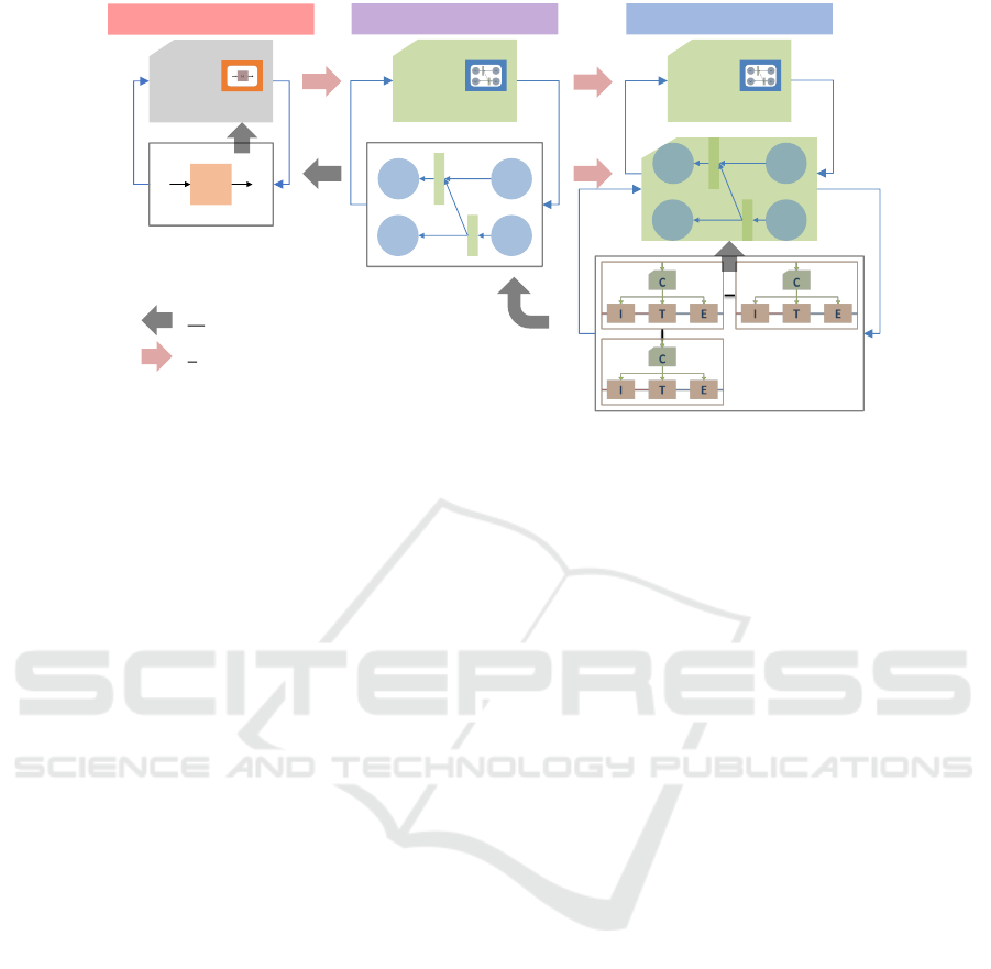
Figure 1: Diagram of electric vehicle cooling and heating circuits (Fiani et al., 2019).
(Borutzky, 2010). The three different modelings are
listed below from the highest abstraction level to the
lowest and will be detailed in Section 2 :
• A teleological modeling where the global mis-
sions and the main properties of the system are
defined.
• A functional modeling that is composed of basic
modular blocks having a specific function. Blocks
are connected to each other with EMI (Energy,
Flow, Matter) flow needs and supplies.
• A multi-physical modeling that is composed of all
physical components and equipment of the sys-
tem. At this level, the behaviour of the compo-
nents and interactions between each other are de-
fined by physical laws.
This methodology is interesting because each ab-
straction level has its own specificities and is used at
different stages in the system design. As illustrated
in Figure 1, this methodology is a circular approach
in which each higher abstraction level can be seen
as a reduction from the lower one. The teleologi-
cal level does not require neither much time nor any
technical knowledge to be developed and gives a first
global overview of the system and its main charac-
teristics. Hence, it is often the first one to be elab-
orated. The functional model is then developed as a
refinement of the teleological one, where the differ-
ent functions of the system and their interactions are
defined. By construction, the functional model con-
tains both a control and an operation part that make
the model self-sufficient, i.e. it can be run on its own.
The major advantage of this modeling is the possibil-
ity to quickly simulate the system already in the first
design stages; it will be especially useful for architec-
ture choices and components sizing. An adaptation of
the teleological level enables the transmission of the
global constraints from the highest level of abstrac-
tion to the functional one. As the design progresses,
a model much closer to experimental observations is
needed. The expansion of each function of the sys-
tem as a set of physical components and the defini-
tion of their interactions lead to the development of
the multi-physical model. Instead of starting from
scratch for the control design of this level, an adap-
tation of the control part of the functional level can
act as the multi-physical model supervisor. Finally,
the end-missions of the system can be introduced in
the control of this lowest abstraction level by a new
adaptation of the teleological level.
The first objective of this work is to connect the
functional model to a global supervisor (correspond-
ing to the teleological level) containing macroscopic
constraints and criteria that can be transmitted to the
functional model through the resolution of an opti-
mization problem that will ensure a better resource
management. The second objective is to build the
control of the multi-physical model using setpoint
values coming from the control part of the func-
tional representation. The coupling between func-
tional and multi-physical models was demonstrated in
(M
¨
ok
¨
ukc
¨
u et al., 2017) on the power-train of a hybrid
electric vehicle and it will be extended here for ther-
mal issues.
In this paper, the methodology is applied to a use-
case consisting in the thermal management system of
an electric vehicle (EV). In internal combustion en-
gine vehicles, cabin heating is ensured by the thermal
energy dissipated by the engine while its cooling is
ensured by a refrigerant loop. The development of
battery electric vehicles brings some new issues:
ICINCO 2020 - 17th International Conference on Informatics in Control, Automation and Robotics
566

• Electric machine does not dissipate enough en-
ergy to satisfy the heating needs.
• The battery has sizable heating and cooling needs
that must be taken into account.
• Battery temperature has a direct influence on its
efficiency, which is a key parameter for the vehi-
cle autonomy.
• The non-negligible impact of battery temperature
on its service life was demonstrated in (Gross and
Clark, 2011).
• The battery charge dissipates a huge amount of
energy that must be evacuated, especially in the
case of fast charging.
Due to these new constraints, a multitude of dif-
ferent technical solutions have been developed, lead-
ing to as many different architectures, as shown in the
large review presented in (Zhang et al., 2018). Hence,
thermal management in electric vehicle is becoming
an important research topic for car manufacturers.
Section 2 describes three models with different
abstraction levels (teleological level, functional level
and multi-physical level), the interconnection be-
tween these models as well as the advantages and
the challenges of the interconnection. In Section 3,
the EV thermal management system is detailed and
modeled at the three levels of abstraction.The issue of
energy management between the consumers is intro-
duced and an optimization problem is formulated at
teleological level of abstraction to address this prob-
lem. Section 4 provides the simulation results of the
functional model, which are confronted to simula-
tions of the multi-physical model for validation. Fi-
nally, concluding remarks and perspectives are pre-
sented in Section 5.
2 MODELING METHODOLOGY
FOR SUPERVISOR
ARCHITECTURE DESIGN
This section describes the three abstraction levels
of modeling introduced in (Fiani et al., 2016) and
(M
¨
ok
¨
ukc
¨
u et al., 2016) and shows how they can be
interconnected between each other.
2.1 Teleological Modeling
The teleological modeling is the one with the higher
level of abstraction and it does not require any tech-
nical knowledge to be elaborated. At this level, only
the main missions and expectations of the system are
represented. Some of the requirements that can be ex-
pressed at this level are listed below:
• Financial and realization time constraints.
• Ecological international standards.
• Constraints related to the integration of the system
in its environment.
• Global performances of the system (lifetime, au-
tonomy, operation energetic cost, etc.).
• Some comfort criteria like maximal noise or vi-
bration levels.
At teleological level are also defined some arbitra-
tion rules that define weighted or heuristic priorities
between the different purposes of the system. For an
electric vehicle, this arbitration level could be illus-
trated by different operation modes:
• A sportive mode that focuses on the power-train
performances.
• A comfort mode, where comfort parameters are
optimized (compressor noise, cabin temperature,
speed variations smoothness).
• A normal mode that tries to meet all criteria, as
best as possible, without favoring any of them.
• An eco mode, in which priority is given to energy
savings.
In the earliest design stages, this level gives a good
overview of the main missions and limitations of the
system while in the last stages, it can be used to in-
troduce optimization algorithms to minimize a global
cost function (financial cost, energy amount, etc.).
2.2 Functional Modeling
The concept of functional modeling has been devel-
oped in (Fauvel et al., 2014) and (M
¨
ok
¨
ukc
¨
u et al.,
2016) and has been illustrated on a hybrid vehicle in
(M
¨
ok
¨
ukc
¨
u et al., 2017). This representation is based
on the use of modular functional blocks assembled to-
gether and connected by EMI flow exchanges. Each
block is composed of both a control part that deter-
mines the flow needs to be transferred to the neigh-
bour blocks, and an operation part that incorporates
the flow supplies received by the block into simple
models, in order to estimate the different variable val-
ues. This architecture of each block enables the func-
tional model to be run on its own. A few functional
elements have been introduced in (M
¨
ok
¨
ukc
¨
u et al.,
2016) and extended to thermal field in (Fiani et al.,
2019).
• Source: receives an EMI flow need (power in the
case of an energetic system) from another element
Functional Model-based Resource Management: An Application to the Electric Vehicle Thermal Control
567
and delivers a flow supply depending on the need
and internal limitations of the source.
• Consumer / Effector: requests an EMI flow to an-
other block that can provide it. The flow is used
to achieve the effector’s objective thanks to a con-
troller or to satisfy the consumer’s flow need.
• Storage: stores EMI according to its maximal ca-
pacity. It can behave as a source (deliver EMI
flow), consumer (receive EMI flow) or both, de-
pending on the system and the scenario.
• Distributor: functional block that collects flow
needs from all the consumers connected to it and
distributes the sum of the flow needs to all the
sources connected to it. The distributor collects
also the flow supplies from the sources and dis-
tributes them to the consumers according to their
request. The distribution to the sources or to the
consumers is made accordingly to their own avail-
ability/acceptance. Distributors can have either a
heuristic strategy or a more complex optimization
algorithm depending on the system.
• Transformer: converts a primary flow in another
one (electrical to mechanical power for example).
An optional efficiency coefficient and flow lim-
itations are available. The process is reversible,
eventually with a different efficiency coefficient.
A transformer can convert two or more flows in
another one and conversely (chemical reaction for
example).
• Actuator: element transforming electrical power
into an action. It receives an action request
(flow, temperature) and asks for electrical power
to achieve the setpoint.
• Exchanger: interface exchanging EMI flow be-
tween two circuits. It receives a flow request from
both neighbours and sends an action request to
two actuators to satisfy the needs. It gets back an
action from the actuators and calculates the flow
transferred and its limitations to each neighbor, to
achieve an equilibrium state. The exchanger block
is fully symmetrical, its both neighbours are con-
sidered as consumer blocks.
These seven elements presented above constitute
the building blocks of the functional modeling. A
multitude of models in a large variety of fields can
be created by assembling these blocks together. Each
block has some editable parameters that can be ad-
justed to fit the considered system.
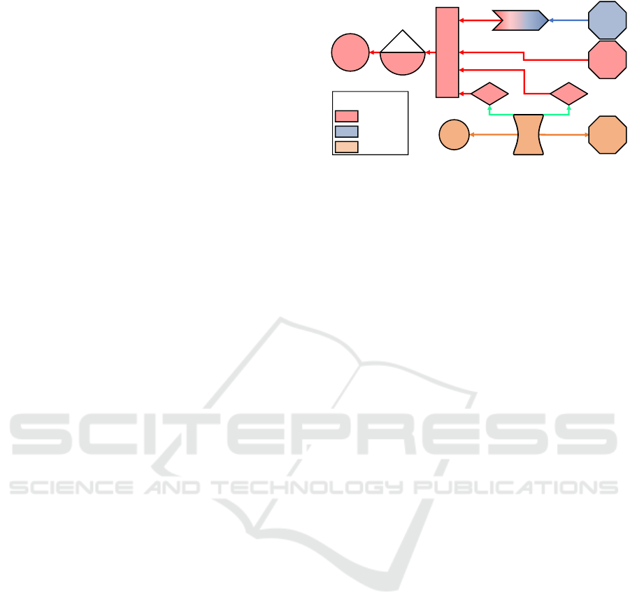
Figure 2 shows the functional model of a complex
system using the seven elements introduced above.
Each geometrical shape corresponds to a specific el-
ement related by arrows that indicate only the need
E2M
Tranformer
Vehicle
Motion
Electrical
Auxiliaries
Battery
Cooling
Thermal
Exchanger
Exterior
Air
Pump
Fan
Electrical
Storage
Electrical
Grid
Electrical
Distributor
Electrical
Mechanical
Thermal
Energetic field:
Figure 2: Simplified functional model of an electric vehicle.
direction (the supply is implicitly in the opposite di-
rection). Green, red and blue arrows represent power
needs (in their respective energetic fields) while green
arrows correspond to flow needs. The system rep-
resented is an electric vehicle composed of elements
from three different fields:
• A mechanical part with the vehicle motion effec-
tor.
• A thermal part composed by a source, a thermal
exchanger and an effector (battery cooling).
• The electrical part, which is the main one, com-
posed by a source, a storage, a distributor that
manages the electrical power needs from two
actuators, a transformer and a consumer (radio,
headlights, etc.).
In the very early stages of the system design, this
model can already be run and provides quick simula-
tion results. The architecture can be easily changed
and the sizing of the components can be adjusted.
Moreover, the energy distribution strategy can be im-
plemented and tested in this functional model, which
is time saving.
2.3 Multi-physical Modeling
According to (Fiani et al., 2016), multi-physical mod-
eling is well suited to represent a technological ele-
ments architecture. A 0D-1D multi-domains model-
ing is necessary and sufficient to accurately represent
a complex system. Each component of the model
is ruled by analytical laws based on the real physi-
cal behaviour of the component in its respective field
(electrical, mechanical, etc.). Components are con-
nected between each other with physical links con-
taining both a flow and an effort variables. Table 1
lists the different flow and effort variables correspond-
ing to each physical domain.
The main advantage of multi-physical modeling
is, as long as the model is well calibrated, to provide
very accurate simulation results compared to what can
be experimentally observed. However, the price to
ICINCO 2020 - 17th International Conference on Informatics in Control, Automation and Robotics
568
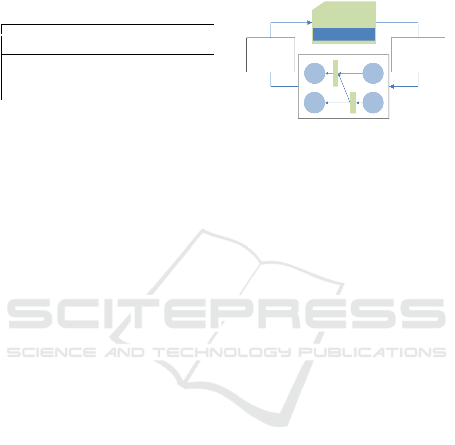
Table 1: Multi-physical ports and connectors (Fiani et al.,
2016).
Energetic field Effort Flow
Mechanical rotation Torque (N.m) Speed rot (rad/s)
Mechanical translation Effort (N) Speed (m/s)
Hydraulic Pressure (Pa) Flow (kg/s)
Thermal Temperature (K) Therm flow (J/s)
Thermo-fluid
Pressure (Pa) Flow (kg/s)
Temperature (K) Enthalpie flow (J/s)
Electric Voltage (V) Current (A)
pay for this accuracy is the simulation time, which
can be very long as soon as the model gets complex.
This is the reason why this kind of modeling is very
useful for the model validation but it should not be
used for designing architecture or control strategies.
2.4 Interconnections between the Three
Levels of Modeling
2.4.1 Teleological and Functional Models
The teleological level gives an overview of the sys-
tem and its global requirements (standards, criteria,
constraints, etc.) of the system. The purpose of inter-
connection is to transmit these global parameters to
the functional level. However, the inputs of the func-
tional model are only setpoints, limitations (minimum
and maximum values) of variables and activation or
not of each element. An interface has to be built to
translate the parameters from the teleological level
into information understandable by the functional el-
ements. For each global parameter, a list of all the
variables estimated by the functional model and re-
quired for the determination of the parameter has to
be established, as well as the functional elements im-
pacted by this parameter. The second step is to evalu-
ate the global requirements achievement and develop
the corresponding equations to relate it to the identi-
fied functional elements.
As an example, an electric vehicle is considered to
illustrate the interconnection between the teleological
and the functional model. One of the requirements of
the teleological model is the maximum comfort noise
level, which is speed dependent (equal to wind noise
at high speeds). In the system, the loudest element is
the compressor. A relationship between compressor
power and noise level has to be established to deter-
mine the maximal power that should be provided to
the compressor.
This interconnection is illustrated in Figure 3
with:
• D
Comp
the compressor availability, i.e. the maxi-
mal power the compressor can provide.
• NoiseLvl the maximal noise level requirement.
S1 C1
C2S2
D
D
Teleological
requirements
(NoiseLvl, …)
Functional
requirements
(D
comp
, …)
Estimated
variables
(VehSpd, …)
Figure 3: Relationship between teleological requirements
and functional model control.
• VehSpd the vehicle speed estimated by the func-
tional model.
2.4.2 Functional and Multi-physical Models
Both functional and multi-physical models are very
useful at different stages of the system design. On
one hand, the first one is very helpful in the early
stages of a system design due to its quick develop-
ment, its modularity and the fast simulations results it
provides. On the other hand, the second one is used in
downstream stages to provide a model, although more
complex and time-consuming, that is much more ac-
curate than the functional one. The functional model
contains both a control and an operation part. The
idea of connecting both models is to reuse the control
part of the functional model to build the supervisor of
the multi-physical level.
However, the flow exchanges are not the same be-
tween the two models. While they are energy-based in
the functional model, the multi-physical model uses
both flow and effort links. Interconnecting both mod-
els is not an immediate result and requires a process
to translate data from one model to another and in-
versely. A solution, consisting in building an interface
between the two models, was developed in (M
¨
ok
¨
ukc
¨
u
et al., 2017). It requires, at first, to determine, for each
multi-physical block, an equivalent in the functional
one (sometimes by combining or splitting elements).
The second step consists in building the equations be-
tween functional and multi-physical domains for each
element. Hence, the interface transforms functional
information into physical signals that are used for the
control of multi-physical components. Moreover, the
variables estimated by the multi-physical model are
sent into functional elements and replace their opera-
tion part.
Functional Model-based Resource Management: An Application to the Electric Vehicle Thermal Control
569
3 APPLICATION TO ELECTRIC
VEHICLE THERMAL
MANAGEMENT
3.1 Motivations
In an electric vehicle, the thermal system is different
from the one in a combustion vehicle as explained in
Section 1. It is mainly composed by the cabin, the
battery and the electric machine (EM). All these com-
ponents have thermal needs and different structures
have been developed by automotive constructors to
satisfy them. The main objectives are to ensure con-
venient temperature both for passengers’ comfort and
for battery, and to maintain the EM integrity. Prior to
trying to optimize the efficiency of the system, the ar-
chitecture that best meets the specifications has to be
elaborated and validated. The functional model is the
first one to be designed because it offers a large flexi-
bility, enables easy architecture changes and provides
quick simulation results.
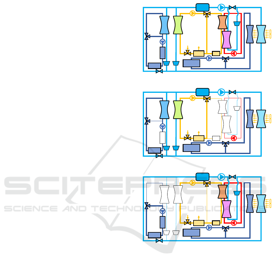
3.2 System Description
The system chosen for this study is a system for which
the multi-physical model had already been developed
and validated with experimental data. The consumers
of this system are the electric machine, the battery and
the cabin. The main energy provider is a refrigerant
loop functioning as a reversible heat pump supply-
ing cold both to the battery and to the cabin as well
as heat to the cabin. The working fluid used in this
system in R134a. The switch between cooling mode
and heating mode of the heat pump is ensured by a
set of regular valves that modify the course of the re-
frigerant in the pipes, and electronic expansion valves
(EXV) that increase or decrease its mass flow. The
evapo-condenser, used in both operating modes, acts
as an evaporator in heating mode while it acts as a
condenser in cooling mode. A diagram of the full
thermal system is available in Figure 4a. Figure 4b
and Figure 4c show how the system behaves in cool-
ing and heating operating mode respectively.
This design is close to the one described in (Zhang
et al., 2019) with two main differences. First, an inter-
mediate water loop was added in this design between
the refrigerant and the heater core to prevent refriger-
ant, which is under high pressure, from leaking into
the air blown into the cabin. The second difference
is that in (Zhang et al., 2019), the design is adapted
to electric vehicles in cold regions. Indeed, according
to (Ding et al., 2020), the optimum operating tem-
perature range for lithium power batteries is from 10
Battery
Electrical
Machine
Air from
Ext
PTC
Compressor
Heater
Chiller
Evaporator
Water
Condenser
Heater
Core
Radiator
Evapo
-
Condenser
EXV
EXV
EXV
Accumu
-lator
Cabin
Air to
Ext
(a) Diagram of electric vehicle cooling and heating circuits.
Battery
Electrical
Machine
Air from
Ext
Compressor
Chiller
Evaporator
Radiator
Evapo
-
Condenser
EXV
EXV
Accumu
-lator
Cabin
Air to
Ext
PTC
Heater
Water
Condenser
Heater
Core
EXV
(b) The cabin and battery mixed cooling mode.
Battery
Electrical
Machine
Cabin
Air from
Ext
Air to
Ext
PTC
Compressor
Heater
Water
Condenser
Heater
Core
Radiator
Evapo
-
Condenser
EXV
Accumu
-lator
Chiller
Evaporator
EXV
EXV
(c) The cabin and battery mixed heating mode.
Figure 4.
◦
C to 35
◦
C. In cold areas, the battery often needs
to be heated up, hence providing the battery’s heat-
ing needs with the heat pump is an attractive solution,
though it makes the design much more complex. In
the design shown below, the heat pump only provides
heat for the cabin while the battery’s heating needs are
provided by a heater. There is an additional positive
temperature coefficient (PTC) in the cabin air loop to
supplement heating supplies to the cabin. The EM
cooling is provided by a water loop exchanging di-
rectly with external air through the radiator. In each
coolant loop, an electrical actuator and eventually a
three-way valve control the flows.
A functional representation of this diagram is
shown in Figure 5. Orange and green links represent
ICINCO 2020 - 17th International Conference on Informatics in Control, Automation and Robotics
570

Cabin
Comfort
Bat Thermal
Conditioning
EM Thermal
Conditioning
Cabin Air
Loop
Bat
Water
Loop
EM
Water
Loop
Heater
Core
Water
Loop
Water
Condenser
Evapo
Chiller
Refri
Loop
Evapo
Condenser
Ext Air
Loop
Radiator
Figure 5: Electric vehicle thermal management diagram.
Energy
Distributor
PTC
Blower
Flow
Distributor
From
Cabin
To Elec
Source
To Heater
Core
To
Evapo
From
Heater Core
From
Evapo
Figure 6: Cabin air loop.
power needs and action needs (mass flow, tempera-
ture, etc.) respectively. Blue blocks are effectors re-
ceiving a setpoint temperature and sending a thermal
power need to achieve it. Red blocks are exchang-
ers that receive thermal power needs from both neigh-
bours and send action needs to actuators to satisfy the
power needs. Lastly, green blocks are coolant loops,
like the cabin air loop expended in Figure 6. They are
composed of a power distributor that splits or gathers
the needs it gets, and at least one electrical actuator
(compressor, fan, blower, pump, PTC, etc.) that tries
to satisfy the action needs it receives. At functional
level, the switch between cooling mode and heating
mode is handled in the ’Refri Loop’ block.
The multi-physical model is represented in Figure
7. The blocks composing the multi-physical model
look similar to those of the functional model. How-
ever, it is important to keep in mind a major differ-
ence between the two models: while functional ele-
ments are connected to each other by means of ener-
getic links independent from their field, the connec-
tions between physical components are composed of
both flow and effort variables that are domain depen-
dent. In order to use the functional model to build
the supervisor of the multi-physical one, the intercon-
nection between analog elements in both models has
to be ensured by an interface, as described in Section
2.4.2.
3.3 Teleological Modeling for Energy
Management
The teleological level enables to introduce global con-
straints and criteria in the system control, like min-
imizing the financial or energetic operation cost. In
this system, in most cases, electric energetic optimiza-
tion can be done only with heuristic strategies directly
implemented in the functional model (for example,
prioritize speeding the blower rather than speeding
the compressor). It means the functional model does
not really need a manager to minimize the global
energetic cost of the system, at least when there is
enough energy to satisfy all the needs. However,
when energy needs are higher than global availabil-
ity of the system, some arbitrations have to be made.
In this system, when the cabin and the battery both
need to be cooled down and the system is saturated
(i.e., needs are higher than global availability), the
cabin or the battery temperature (or both) have to be
degraded in regard to their setpoints. In this case, a
method is required to manage how each temperature
is degraded.
The first option is to implement directly in the
distribution block (of the functional model) priorities
between the consumers when needs are higher than
availability. This method is quick to set up and priori-
ties are not necessarily exclusive but can be weighted
with coefficients. The main inconvenient is that this
prioritization is based on energy and not on temper-
ature setpoints achievement. The link between en-
ergy provided and temperature is dependent on the
scenario, which reduces the modularity of this option.
The second option consists in introducing in the
teleological model a new criterion corresponding to
the system non-saturation (when needs are lower or
equal than global availability). This requirement can
be met by degrading the temperature setpoints up-
stream, resulting in lowering cabin and battery needs.
A simplified functional model is needed to estimate
the pairs of cabin and battery temperature setpoint
values that prevent the system from saturating and
lead to the closest temperature achievements to the
ideal temperatures (defined by the passengers or the
constructor). The connection between the teleological
model and the functional requirements is established
by solving the following optimization problem:
min
T
sp
cab
,T
sp
bat
δ(T
sp
cab
, T
sp
bat
) (1)
s.t.
0 < P
ratio
=
P
act
(H)
P
max
act
< 1 (2)
Functional Model-based Resource Management: An Application to the Electric Vehicle Thermal Control
571
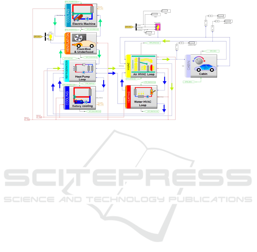
Figure 7: Electric vehicle thermal management multi-physical model.
with δ(T
sp
cab
, T
sp
bat
) = (T
cab
(H) −T
id
cab
)
2
+α·(T
bat
(H) −
T
id
bat
)
2
and:
• α a weighting parameter used to prioritize the
degradation of one temperature in regard to the
other.
• H the time horizon used to simulate the simplified
functional model at teleological level.
• T
cab
and T
bat
the temperatures of the cabin and the
battery respectively, estimated over the time hori-
zon by the reduced functional model.
• T
sp
cab
and T
sp
bat
the temperature setpoints of the
cabin and the battery respectively, which are the
decision variables.
• T
id
cab
and T
id
bat
the ideal temperature setpoints of the
cabin and the battery respectively (values fixed by
the user for the cabin and by the constructor for
the battery).
• P
ratio
the load level of the system taking values
between 0 and 1; these values correspond to a
paused system or a saturated system respectively.
• P
act
and P
max
act
the power provided by the limiting
actuator and the maximum power it can provide
respectively.
The cabin and battery optimal temperature set-
point values, solutions of the optimization problem
(1) will be noted T
sp,∗
cab
and T
sp,∗
bat
respectively. The
strong non linearity of the problem does not enable
the implementation of a classic predictive functional
control. The description of the method is detailed be-
low:
1. Develop a simplified functional model that can
be run faster than the full functional one. It re-
ceives some variables estimated by the full func-
tional model (battery and cabin temperatures, sys-
tem saturation, etc.).
2. Run this model over a time horizon H for T
sp
cab
in
{T
sp
c,1
,T
sp
c,2
,...,T
sp
c,n
c
} and T
sp
cab
in {T
sp
b,1
,T
sp
b,2
,...,T
sp
b,n
b
},
n
c
and n
b
being the number of setpoint values
tested for the cabin temperature and the battery
temperature respectively.
3. Get two matrices of size n
c
x n
b
: the first having
as elements the criterion values obtained for all
the admissible pairs (T
sp
c,i
,T
sp
b, j
), with i = 1 : n
c
and
j = 1 : n
b
, and the second one being composed of
elements of 1 if the constraint (2) is satisfied or 0
in the opposite case.
4. Choose the (T
sp
c,i
,T
sp
b, j
) pair that satisfies the con-
straint (2) and minimizes the criterion, such that
(T
sp,∗
cab
, T
sp,∗
bat
) = (T
sp
c,i
, T
sp
b, j
).
5. Send the new setpoints, T
sp,∗
cab
and T
sp,∗
bat
, to the
functional model for the next time step T
s
. To
avoid brutal setpoint changes in entry of the func-
tional model, a first-order filter is applied on the
setpoints.
The main advantage of this method, though it is
more complex to elaborate, is to be independent from
the scenario and based only on the setpoints. Another
benefit of this approach is the possibility of includ-
ing other parameters than temperature setpoints in the
criterion as well as other constraints than system sat-
uration.
ICINCO 2020 - 17th International Conference on Informatics in Control, Automation and Robotics
572
4 SIMULATION RESULTS
The characteristics of the EV thermal system are sum-
marized in Table 2. A strong assumption is that the
electric power is not limited, i.e. the electric battery
can provide all the electric needs.
Table 2: Thermal system characteristics.
System characteristics Value Unit
Battery mass 500 kg
Battery max thermal exchange 3000 W
Battery charge thermal exchange 5000 W
Compressor max speed 6500 rpm
Compressor displacement 34 cm
3
/rev
Parking fan air velocity max 1.5 m/s
130 km/h fan air velocity max 3.9 m/s
Subsection 4.1 and Subsection 4.2 present the
simulation results of two use-cases run under the same
conditions (same vehicle speed, environment, etc.).
The only difference between the two use-cases comes
from the cabin and the battery temperature setpoints
sent to the model. In the first case, setpoints corre-
spond to ideal constant values while in the second
one, the setpoints are determined by the supervisor
described in Subsection 3.3. Table 3 lists the condi-
tions used for both use-cases. The chosen scenario
consists in a fifty minutes car drive under extreme
climatic condition. The scenario also includes a 10
minutes battery charge (time interval [1200, 1800] s),
during which the passengers stay in the car.
Table 3: Cool-down scenario parameters.
Time (min) 0-20 20-30 30-50
Vehicle speed (km/h) 70 0 70
Road slope (%) 0
Exterior temperature
(
◦
C)
45
Battery charge Off On Off
Sun power (W) 1000
People in the car Yes
Ideal max cabin tem-
perature T
id
cab
(
◦
C)
23
Ideal max battery tem-
perature T
id
bat
(
◦
C)
40
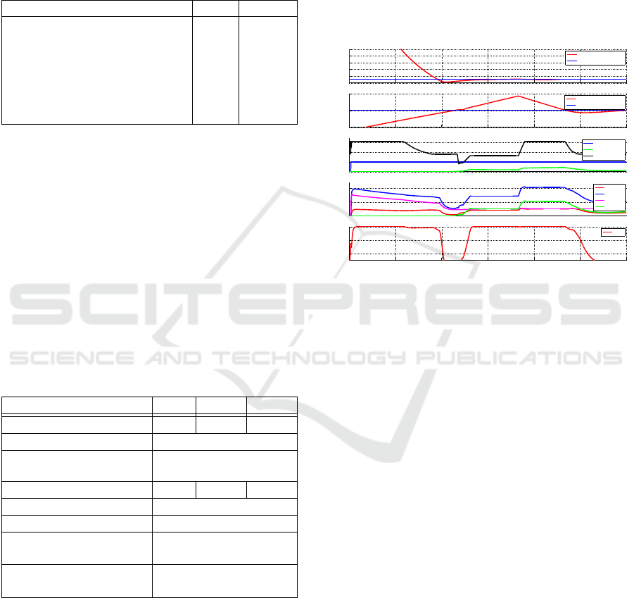
4.1 Functional Model Simulation
First, the functional model is run under the condi-
tions detailed in Table 3. The cabin and the battery
temperature setpoints are constant and equal to T
id
cab
and T
id
bat
respectively throughout the whole simula-
tion. The controller of the distributor in the refrig-
erant loop uses weighted priorities. It means that both
consumers (battery and cabin) are assured to get at
least, if needed, a predefined percentage of the to-
tal available power. Here the weights are set up to
(0.5;0.5), meaning that each consumer can have half
of total available power. If one of them needs less, it
can be reported on the other one. The initial tempera-
ture of the cabin and the battery are 55
◦
C and 34
◦
C
respectively and the temperature setpoints are set to
their ideal max temperature (see Table 3). Simulation
results are given in Figure 8.
22
24
26
28
30
32
Temperature (°C)
Cabine Temperature
Tair Cabin
Tair Cabin SetPoint
35
40
45
Temperature (°C)
Battery Temperature
Twater Battery
Twater Bat SetPoint
0
0.2
0.4
0.6
Mass Flow (kg/s))
Coolants Mass Flow
Q Blower
Q Bat Pump
Q FAN
0
5
10
Power (kW)
Components Power
Pcomp
Pcond
Pevapo
Pchill
0 500 1000 1500 2000 2500 3000
0.6
0.8
1
Time [s]
System Saturation (−)
System Satruration
cost
Figure 8: Functional model simulation with constant tem-
perature setpoints.
A first phase can be observed between 0 s and
1000 s: only the cabin is cooled down while the bat-
tery has not reached the critical temperature yet. Dur-
ing the second phase, the battery is on charge and
needs to evacuate a large thermal power, the system
becomes saturated, the setpoints can not be reached
anymore. Only the battery temperature is degraded
while the cabin temperature remains at the setpoint. It
is because the cabin needs less than 50% of the avail-
able power and gets it as explained above.
4.2 Functional Model Driven by the
Teleological Requirements
The functional model is run once again under the
same conditions introduced in Table 3, exept in this
use-case the temperature setpoints are determined by
the supervisor described in Subsection 3.3 instead of
being constant. Parameters of the supervisor are listed
in Table 4.
The coefficient α determines the degradation of
the battery ideal temperature achievement in regard to
the cabin one. In this simulation, α is set to 1, which
means that both temperatures should be degraded at
the same rate.
The results are presented in Figure 9. As long as
Functional Model-based Resource Management: An Application to the Electric Vehicle Thermal Control
573
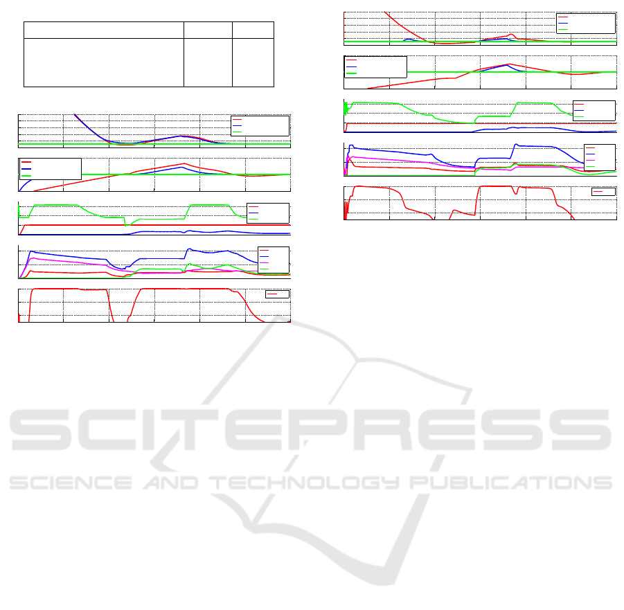
Table 4: Supervisor parameters.
Supervisor characteristics Value Unit
Time horizon H 60 s
Time step T
s
10 s
Weighting parameter α 1 -
22
24
26
28
30
32
Temperature (°C)
Cabine Temperature
Tair Cabin
Tair Cabin SetPoint
Ideal Tair cabin
35
40
45
Temperature (°C)
Battery Temperature
Twater Battery
Twater Bat SetPoint
Ideal Twater Bat
0
0.2
0.4
0.6
Mass Flow (kg/s))
Coolants Mass Flow
Q Blower
Q Bat Pump
Q FAN
0
5
10
Power (kW)
Components Power
Pcomp
Pcond
Pevapo
Pchill
0 500 1000 1500 2000 2500 3000
0.6
0.8
1
Time [s]
System Saturation (−)
System Satruration
cost
Figure 9: Functional model simulation with global supervi-
sor control.
the system is not saturated, it has the same behaviour
than previously without global supervisor. During the
saturation phase, between 1200 s and 2400 s, it can
be observed that both cabin and battery temperatures
are degraded at a similar rate. Taking α greater than
1 would lead to a degradation of the battery temper-
ature faster than the cabin temperature, while taking
α smaller than 1 would have the opposite effect. At
1800 s, which is the most critical moment, battery and
cabin temperatures are 2.6
◦
C and 3.2
◦
C above the
setpoint respectively. Moreover, the system saturation
is close to 1 when setpoints are degraded. This means
that the management of the temperatures degradation
rates does not affect the performance of the system,
which still uses 100% of its capacities when needed.
The control strategy can be tested and modified at this
stage to better meet the constructor requirements.
4.3 Validation on the Multi-physical
Model
The functional model is then adapted and used as a su-
pervisor for the multi-physical model. The functional
model is itself connected to a supervisor computing
the setpoints values as described in Subsection 4.2.
The simulation is run under the same conditions pre-
sented in Table 3 and the results are shown in Figure
10.
The overall behaviour of the system corresponds
to the expectations and the temperature setpoints are
22
24
26
28
30
32
Temperature (°C)
Cabine Temperature
Tair Cabin
Tair Cabin SetPoint
Ideal Tair cabin
35
40
45
Temperature (°C)
Battery Temperature
Twater Battery
Twater Bat SetPoint
Ideal Twater Bat
0
0.2
0.4
0.6
Mass Flow (kg/s))
Coolants Mass Flow
Q Blower
Q Bat Pump
Q FAN
0
5
10
Power (kW)
Components Power
Pcomp
Pcond
Pevapo
Pchill
0 500 1000 1500 2000 2500 3000
0.6
0.8
1
Time [s]
System Saturation (−)
System Satruration
cost
Figure 10: Multi-physical model simulation controlled by
adapted functional model, itself monitored by a global su-
pervisor.
achieved when it is possible (i.e. available power is
greater than total power needs). Some observations
can be made about the simulation:
• The system needs about 1000 s to achieve the
cabin temperature setpoint, which corresponds to
experimental observations for similar systems.
• The setpoint overshoots are 0.6
◦
C and 0.7
◦
C
for the cabin and the battery temperature respec-
tively, which is completely reasonable in this kind
of thermal system.
• At 1200 s, the battery gets charged, a large amount
of thermal energy coming from Joule effect needs
to be dissipated, leading to a singular point on the
battery temperature curve.
• At 1800 s, the battery is disconnected and the
driver starts driving. The mass flow available at
the fan is much bigger and the energy availability
for the consumers as well. The system saturation
gets down to 90 % for about one minute around
1800 s because the refrigerant loop needs to ac-
commodate to the new situation.
5 CONCLUSION
In this work, a methodology for the modeling and
design of a complex system and the development
of its control has been introduced. This methodol-
ogy uses three levels of abstraction that are based
on purposes definition, energy links and physical
laws respectively. The three levels are interconnected
and exchange information and control parameters be-
tween each other. The teleological level gives a good
overview of the system main missions. It introduces
ICINCO 2020 - 17th International Conference on Informatics in Control, Automation and Robotics
574

global criteria and arbitration rules that can be sat-
isfied by means of heuristic models or by solving
optimization problems. The functional level enables
to run fast simulations and get approximated results
in the early stages of system design, which provides
a good way to test and validate control strategies.
Also, architecture changes are easy and not much
time-consuming at this level. Lastly, a multi-physical
model well calibrated can provide results close to ex-
perimental data and enables to evaluate a large vari-
ety of scenarios with good accuracy. This method-
ology was applied to a thermal management system
use-case and has provided positive results. A non-
saturation criterion has been introduced in the teleo-
logical level in order to improve the resource manage-
ment with critical conditions.
A first perspective of this work is to use this three-
level abstraction modeling to optimize the global en-
ergy consumption of a system. An interesting use-
case could be a whole electric vehicle composed by
the thermal management and the power-train subsys-
tems.
Another objective is the extension of the func-
tional modeling to systems in which energy and mat-
ter flows are coupled. A use-case could be a water
recycling system, in which consumers have both mat-
ter (water) and energy (heat) needs that must be dis-
tributed between matter or energy (or both) sources.
Future work intends to develop and implement op-
timization algorithms directly in the functional model.
Lastly, the teleological level could integrate some
levels of arbitration between several missions of the
system, which would have several operating modes
optimizing different objectives.
REFERENCES
Borutzky, W. (2010). Bond Graph Methodology: Develop-
ment and Analysis of Multidisciplinary Dynamic Sys-
tem Models. Springer-Verlag London.
Brunet, J., Flambard, L., and Yazman, A. (2005). A hard-
ware in the loop (hil) model development and imple-
mentation methodology and support tools for testing
and validating car engine electronic control unit. In
International Conference on Simulation Based Engi-
neering and Studies, TCN CAE, Lecce, Italy.
Ding, P., Wang, Z., Wang, Y., and Li, K. (2020). A dis-
tributed multiple-heat source staged heating method
in an electric vehicle. Renewable Energy, 150:1010–
1018.
Fauvel, C., Claveau, F., and Chevrel, P. (2014). Energy
management in multi-consumers multi-sources sys-
tem : a practical framework. In IFAC World Congress.,
pages 2260–2266, Cape Town, South Africa.
Fiani, P., Boyer, B., Brunet, C., and Bruniquel, G. (2019).
Utilisation de la mod
´
elisation
´
energ
´
etique fonction-
nelle pour la synth
`
ese thermique des v
´
ehicules hy-
brides et
´
electriques. In SIA Simulation num
´
erique :
La simulation num
´
erique au sein de l’innovation au-
tomobile., Saint-Quentin en Yvelines, France.
Fiani, P., Chavanne, S., Taleb, L. A., and M
¨
ok
¨
ukc
¨
u,
M. (2016). Mod
´
elisation pour la conception et
l’
´
evaluation de syst
`
emes complexes. Revue Ing
´
enieurs
de l’automobile, 841.
Gross, O. and Clark, S. (2011). Optimizing electric vehicle
battery life through battery thermal management. SAE
International Journal of Engines.
M
¨
ok
¨
ukc
¨
u, M., Fiani, P., Chavanne, S., Taleb, L. A., Vlad,
C., and Godoy, E. (2017). Control architecture mod-
eling using functional energetic method: Demonstra-
tion on a hybrid electric vehicle. In 14th Interna-
tional Conference on Informatics in Control, Automa-
tion and Robotics (ICINCO), Madrid, Spain.
M
¨
ok
¨
ukc
¨
u, M., Fiani, P., Chavanne, S., Taleb, L. A., Vlad,
C., Godoy, E., and Fauvel, C. (2016). A new concept
of functional energetic modelling and simulation. In
The 9th Eurosim Congress on Modelling and Simula-
tion., Oulu, Finland.
Von Bertalanffy, L. (1968). General System Theory. George
Braziller, Inc.
Zhang, K., Li, M., Yang, C., Shao, Z., and Wang, L. (2019).
Exergy analysis of electric vehicle heat pump air con-
ditioning system with battery thermal management
system. Journal of Thermal Science, 29(2):408–422.
Zhang, Z., Wang, J., Feng, X., Chang, L., Chen, Y., and
Wang, X. (2018). The solutions to electric vehicle air
conditioning systems: A review. Renewable and Sus-
tainable Energy Reviews, 91:443–463.
Functional Model-based Resource Management: An Application to the Electric Vehicle Thermal Control
575
