
A Bio-inspired Quasi-resonant Compliant Backbone for Low Power
Consumption Quadrupedal Locomotion
Edgar A. Parra Ricaurte
1 a
, Julian D. Colorado
2 b
, S. Dominguez
1 c
and C. Rossi
1 d
1
Centre for Automation and Robotics UPM-CSIC, Madrid, Spain
2
Department of Electronics Engineering, Pontificia Universidad Javeriana, Bogot
´
a, Colombia
Keywords:
Bio-inspiration, Quadrupedal Locomotion, Compliant Structures, Power Efficiency.
Abstract:
Many quadrupeds are capable of highly power efficient gaits thanks to their flexible backbone. This is used
during different stages of the gait in order to store and release elastic energy, also helping a smooth deceleration
and a fast acceleration of the different parts of the body involved during running. In this work we present our
current studies aimed to reproduce such phenomena for efficient robot locomotion. In addition, we studied
how to amplify such effect when the frequency of the oscillations is brought close to the natural resonant
frequency of the compliant structure. We demonstrated that a flexible artificial structure representing the
backbone, muscle and tendons, driven to quasi-resonant oscillations is capable of dramatically reducing the
power required to maintain oscillations. At the same time, these reach a bigger amplitude. Such effect will be
used to design fast running and energy efficient quadruped robots.
1 INTRODUCTION
Legged locomotion is of great interest in field robotics
because it allows great stability on rough terrains and
agile movements, as demonstrated by the latest ad-
vances in quadruped robots such as Spot by Boston
Dynamics
1
. The body of literature in this field is
fairly big, focussing mainly in mechatronic design
and control. (Raibert, 1986) is one the earliest works
dealing with dynamic legged robots, and other walk-
ing robots are described in (De Santos et al., 2007),
(Semini et al., 2011).
Further works aimed at developing legged robots
that not only walk, but that are also capable of gal-
loping at high speeds, such as the BigDog (Raibert
et al., 2008), KOLT (Nichol et al., 2004), Scout II
(Poulakakis et al., 2005), Star1ETH (Gehring et al.,
2013) and the MIT Cheetah 2 (Park et al., 2014). All
these robots are capable of robust locomotion on may
different terrains. However, the structure of their bod-
ies is rigid. Compared to their natural counterparts,
like e.g. cheetahs, horses and greyhounds such feature
a
https://orcid.org/0000-0001-6595-5420
b
https://orcid.org/0000-0002-6925-0126
c
https://orcid.org/0000-0002-9498-5407
d
https://orcid.org/0000-0002-8740-2453
1
https://www.bostondynamics.com
does not allow them to take advantage of the flexibil-
ity of the trunk in order to be able to gallop at high
speed with great power efficiently (Alexander, 1988).
In our current work, we aim at designing a legged
robot with high power efficiency and fast speed, there-
fore we focus precisely on such key feature.
In this topic, several investigations have focused
on understanding and developing the bending of the
trunk, evidencing three types of flexible trunks: ac-
tuated, semi-actuated and passive. In (Culha and
Saranli, 2011) it is shown how galloping performance
of a quadrupedal can be improved by placing an ac-
tuated joint for flexion and extension of the trunk,
and compared this one with a rigid robot body, like-
wise (Bhattacharya et al., 2019) shows the advantages
of actuated spine by means of robot Stoch2. They
demonstrated that the former allows increased speed
and long stride. In (Eckert et al., 2015) a comparison
between 3 types of trunks using the Lynx-robot, one
actuated for flexion and extension movements, and
two actuated only for the flexion movement, and us-
ing a glass fibre rod with different stiffness as passive
actuator for extension. In (Phan et al., 2017) the dif-
ference between rigid and passive articulated trunk, is
investigated, showing that the latter has the advantage
of performing longer strides and affects significantly
the dynamics of the robot and its power efficiency. In
242
Parra Ricaurte, E., Colorado, J., Dominguez, S. and Rossi, C.
A Bio-inspired Quasi-resonant Compliant Backbone for Low Power Consumption Quadrupedal Locomotion.
DOI: 10.5220/0009770402420249
In Proceedings of the 17th International Conference on Informatics in Control, Automation and Robotics (ICINCO 2020), pages 242-249
ISBN: 978-989-758-442-8
Copyright
c
2020 by SCITEPRESS – Science and Technology Publications, Lda. All rights reserved

(Tsujita and Miki, 2011), the stability of gait patterns
with variable trunk stiffness is investigated.
It is important to highlight that while in most
rigid-bodied quadrupedal robots the legs’ mass is con-
sidered negligible for the purpose of studying robot’s
body dynamics, when it comes to flexible backboned
legged robots, this plays a key role, since the mov-
ing masses of the legs (plus tail and head) and their
contact with the ground concur to toe trunk bending
that accumulates and releases energy, especially dur-
ing trot and gallop (Alexander, 1984; Day and Jayne,
2007)
2
.
In this paper we aim at studying and character-
ising these phenomena, with the additional purpose
of demonstrating that a dramatic power saving is
obtained driving the oscillations of the trunk to a
quasi-resonant regime. Such effect has been stud-
ied e.g. in (Maheshwari et al., 2012), (Iida et al.,
2012) and (Reis and Iida, 2014) for hopping robots
and robots with compliant legs. Such effect has also
been demonstrated on flexible backbones for fish-like
robots (Coral et al., 2015).
The paper is organised as follows. Section 2 ex-
plains the mathematical analysis performed to know
the fundamental frequencies and vibration modes for
known dimensions of an Aluminum beam. In Sec-
tion 3 we explain the mechanical design and hardware
components of the testbed used for experimental anal-
ysis. Section 4 details the control scheme used in or-
der to achieve continuous vibration while maintaining
a given frequency. Section 5 reports the results of the
experiments, and Section 6 concludes the paper with
a discussion on the results and future work.
2 MATHEMATICAL ANALYSIS
For the purpose of concept proving our approach, the
trunk of a quadrupedal is modelled as a flexible beam
made of aluminum, with two masses at its ends repre-
senting the hind and forelegs. The oscillating move-
ment is provided by a mechanical system representing
the trunk musculature. The details of the models are
shown in Figure 1.
In order to calculate the natural frequencies and
mode shapes of a cantilever Euler-Bernoulli beam
carrying a point mass, we used the Superposition
Method (Rao, 2011), how can be seen in the Figure
(2). Using this method, the modal coordinate and
2
A similar effect is also present in insects and birds,
whose thorax contain compliant structures that accumulate
and release energy during the flapping cycle at the bene-
fit of power consumption, but also flight stability, see, e.g.
(Zhang and Rossi, 2017; Zhang and Rossi, 2019).
Backbone
Hindlegs
Muscles
Forelegs
Figure 1: Model of the system.
mode shapes functions must be calculated. These
have been calculated by means of separation of vari-
ables and Laplace transformation (Skoblar et al.,
2017). The model of the cantilever Euler-Bernoulli
beam carrying a point mass is defined by the follow-
ing equation:
EI
∂
4
w
∂x
4
+ ρA
∂
2
w
∂t
2
+ M
∂
2
w
∂t
2
δ(x − x
M
) = 0 (1)
where E the Young’s model, I second moment of area,
w cross displacement, ρ beam material density, A the
cross-section area, M the mass point values and x
M
the coordinate of the point mass.
Figure 2: Diagram of Euler-Bernoulli cantilever beam car-
rying a point mass M.
Taking into account the physical restrictions and
the fourth-order partial differential equation (1), it is
necessary to have boundary conditions to determine a
solution of system. We have four boundary conditions
for a cantilever beam, since the number of boundary
conditions must coincide with the order of the partial
differential equation, which are for clamped-free and
free-free conditions. In out case, the former applies.
2.1 Natural Frequencies and Mode
Shapes of Clamped-free Boundary
Condition
Considering equation (1), the following boundary
conditions are needed to find the natural frequencies
and mode shapes.
w(0,t) = w
0
(0,t) = w
00
(L,t) = w
000
(L,t) = 0 (2)
A Bio-inspired Quasi-resonant Compliant Backbone for Low Power Consumption Quadrupedal Locomotion
243

where w is the lateral displacement of the beam and
the derivatives with respect to x are the different con-
ditions of the ends beam. As mentioned before, dif-
ferential equation (1) is solved by means of separation
of variables. Therefore, displacement is defined as the
product of two separate functions, which depend one
on the position and the other on time.
w(x,t) = ψ(x)sin(ωt) (3)
where ψ(x) is the mode shape and sin(ωt) represents
of harmonic vibration with angular natural frequency
ω. Hence, taking into account the separation of vari-
ables, including equation (3) into (1), performing the
corresponding derivatives and dividing by sin(ωt), we
obtain:
EIψ(x)
(4)
− ρAω
2
ψ(x) − Mω
2
ψ(x)δ(x − x
M
) = 0
(4)
EIψ(x)
(4)
− (ρA +Mδ(x − x
M
)
| {z }
ε(x)
)ω
2
ψ(x) = 0 (5)
Function ε(x) called weighting function.
Applying the Laplace transform in equation (5)
with respect to x coordinate, we obtain:
EI[s
4
L {ψ(x)} − s
3
ψ(0) − s
2
ψ(0)
0
− sψ(0)
00
−ψ(0)
000
] − ρAω
2
L {ψ(x)}
−Mω
2
e
−sx
M
ψ(x
M
) = 0
(6)
Boundary conditions indicated in (2) must be main-
tained despite applying the separation of variable (3).
Since as aforementioned above, this conditions helps
to determine a solution taking into account the physi-
cal restrictions and the order of the partial differential
equation. Therefore, it being possible to obtain the
following conditions with the mode shape:
ψ(0) = ψ(0)
0
= ψ(L)
00
= ψ(L)
000
= 0 (7)
Applying these conditions to equation (6), the follow-
ing expression is obtained:
sψ(0)
00
+ ψ(0)
000
+
Mω
2
EI
e
−sx
M
ψ(x
M
) =
L {ψ(x)}
s
4
−
ρAω
2
EI
(8)
By rearranging equation (8), we obtain:
L {ψ(x)} = ψ(0)
00
s
s
4
− k
4
+ ψ(0)
000
1
s
4
− k
4
+
Mω
2
ψ(x
M
)
EI
e
−sx
M
s
4
− k
4
(9)
where k is the wave number, which can be calculated
with the following expression:
k =
ω
2
ρA
EI
1/4
(10)
Performing the inverse transform, the following ex-
pression is obtained:
ψ(x) = ψ(0)
00
cosh(kx) − cos(kx)
2k
2
+ψ(0)
000
sinh(kx) − sin(kx)
2k
3
+
Mω
2
ψ(x
M
)
EI
U(x − x
M
)
sinh(kx − kx
M
) − sin(kx − kx
M
)
2k
3
(11)
To calculate the values of ψ(0)
00
and ψ(0)
000
, the func-
tion (11) is derived taking into account the conditions
ψ(L)
00
= ψ(L)
000
= 0. Therefore, the second and third
derivative of the function is performed and change x
by L. Obtaining the following expressions:
0 = ψ(L)
00
= ψ(0)
00
(
A
z }| {
cosh(kL) + cos(kL))
+
ψ(0)
000
k
(
B
z }| {
sinh(kL) + sin(kL)) +
Mω
2
ψ(x
M
)
EIk
(
C
z }| {
sinh(kL − kx
M
) + sin(kL − kx
M
))
(12)
0 = ψ(L)
000
= ψ(0)
00
k(sinh(kL) − sin(kL)
| {z }
D
)
+ψ(0)
000
(cos(kL) − cosh(kL)
| {z }
F
) +
Mω
2
ψ(x
M
)
EI
(cosh(kL − kx
M
) + cos(kL − kx
M
)
| {z }
G
)
(13)
The expressions indicated by letters A, B, C, D, F
and G, in (12) and (13) are used for convenience in
order to compute the values ψ(0)
00
and ψ(0)
000
. Then,
0 = ψ(0)
00
A +
ψ(0)
000
k
B +
Mω
2
ψ(x
M
)
EIk
C (14)
0 = ψ(0)
00
kD + ψ(0)
000
F +
Mω
2
ψ(x
M
)
EI
G (15)
and
ψ(0)
00
=
Mω
2
ψ(x
M
)
EIk
R
z }| {
−
BG −CF
BD − AF
(16)
ψ(0)
000
=
Mω
2
ψ(x
M
)
EI
AG −CF
BD − AF
| {z }
S
(17)
Including (16) and (17) into (11 ), and rearranging the
expression the mode shape is obtained:
ψ(x) =
Mω
2
ψ(x
M
)
2EIk
3
[R(cosh(kx) − cos(kx))
−S(sinh(kx)− sin(kx))
+U(x − x
M
)(sinh(kx − kx
M
) − sin(kx − kx
M
))]
(18)
ICINCO 2020 - 17th International Conference on Informatics in Control, Automation and Robotics
244
By obtaining the mode shape, the natural frequencies
of the clamped-free model can be calculated.
For this research was used a aluminium beam with
height h = 0.015 m, width w = 0.00302 m and length
L =0.732 m, density ρ = 2700 kg/m
3
and Young’s
module E =70 GPa. It was used a sphere mass of
ABS plastic with a mass M =0.0464 kg, being this
mass positioned at x
M
= 0.710 m.
With the previous data and changing x by x
M
in
equation (18) it is obtained an expression in the form
f (k) = 0, which allows to find the values of k, wave
number. And from equation (10), the natural frequen-
cies can be obtained, confirming the accuracy of the
analytical data with Abaqus 2019 was used. Table
1 shows the four main frequencies computed for the
beam.
Table 1: Natural frequencies of the clamped-free boundary
conditions.
Natural
Frequencies
No
Abaqus
Data
Hz
Analytic
Data
Hz
Analytic
Data
rad/s
1 2.704 2.704 16.993
2 23.423 23.424 147.182
3 71.947 71.961 452.145
4 147.710 147.769 928.463
3 TEST PLATFORM
In order to experimentally assess the result of the
mathematical analysis described in the previous sec-
tion, a platform was created that could produce con-
tinuous oscillations.
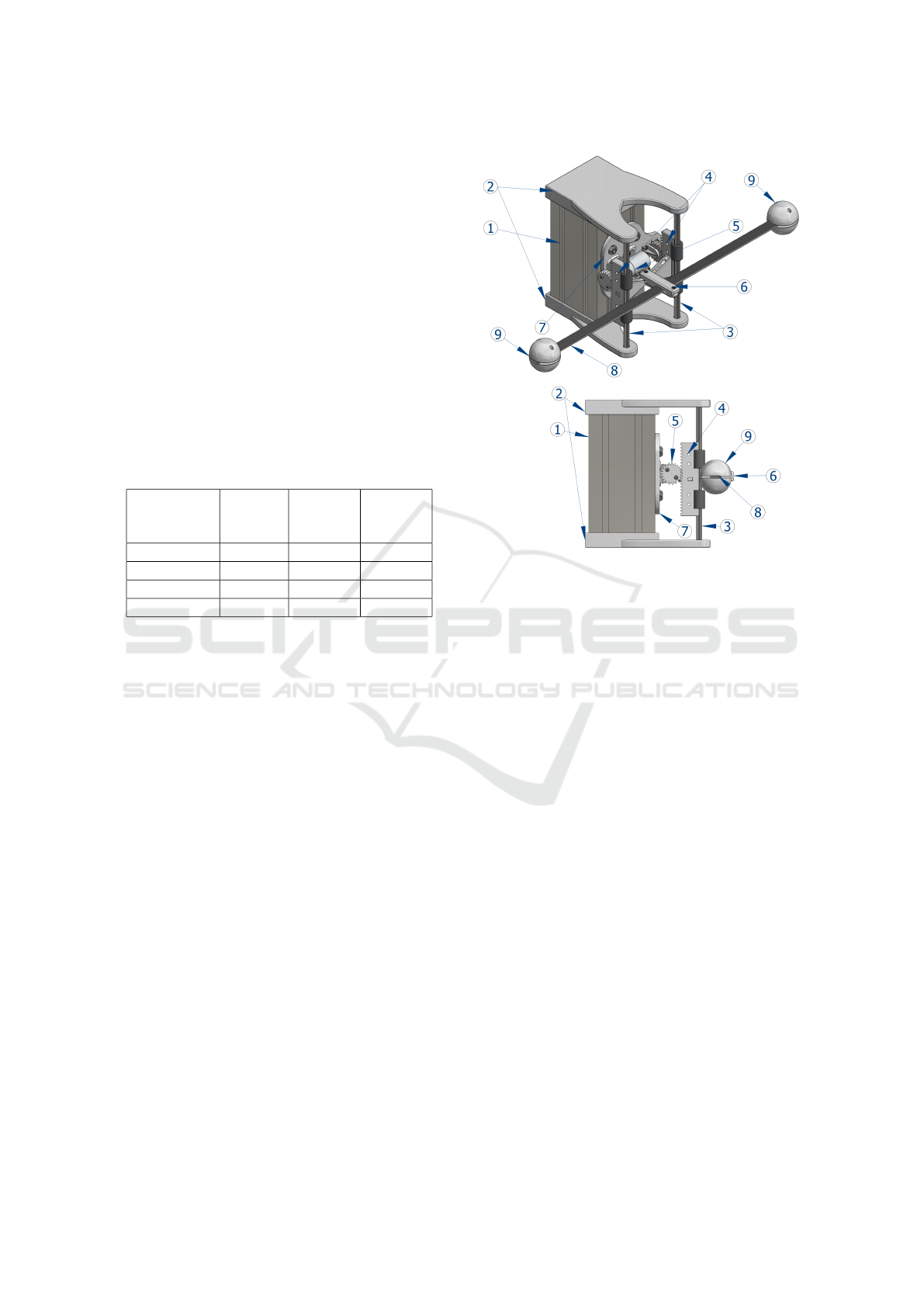
3.1 Mechanical Design
Figure 3 depicts the main elements of the system,
composed of (1) a metallic axis of aluminium on
which (2) two ABS plastic 3D printed covers are fas-
tened, both holding (3) two aluminum rails. On these
rails (4) two sliding bases, which with the help of 4
bearings allow vertical movement of this bases.
These sliding bases together with the (5) pinion-
motor form a rack-pinion system that convert the
circular movement to a lineal-vertical movement. (6)
A platform, that is fastened in the sliding bases, holds
in the middle the (8) aluminum beam. To maintain
fixed the pinion-motor system on the metallic axis
of aluminium, this one is held with (7) a ABS
plastic 3D printed base. Finally, (9) two ABS plas-
tic 3D printed masses are held on the aluminum beam.
a)
b)
Figure 3: a) Isometric and b) lateral view of the mechanism
with scale beam.
The following list specifies each of the compo-
nents indicated in Figure 3.
1. Metallic axis: Extruded aluminum profile being
181 mm of height, 90 mm in width and 90 mm in
depth. It has 8 rail spaces where pieces with screw
of M8 can be held.
2. ABS plastic 3D printed covers: They are two ABS
plastic 3D printed covers being 20 mm in height,
100 mm in width, 170 mm in depth and filling of
70%.
3. Aluminum rails: They are two aluminum rails
with diameter of 8 mm and 191 mm in length.
4. Sliding bases: They are two ABS plastic 3D
printed sliding bases being 100 mm in height, 10
mm in width and 25 mm in deep. They have got a
lineal rack-teeth with module of 1.3 mm.
5. Pinion-motor: The system is composed by a 12V
brushed DC motor with a 34:1 metal spur gear-
box with its corresponding 48 CPR encoder and
an ABS plastic 3D printed pinion with a width of
8 mm, module of 1.3 mm and radius 15 mm with
a filling of 70%.
6. Platform: It is ABS plastic 3D printed platform
being 30.23 mm in height, 87.1 mm in width and
63.5 mm in depth. Its design allows to hold the
aluminium beam by mean of M3 Allen bolts.
A Bio-inspired Quasi-resonant Compliant Backbone for Low Power Consumption Quadrupedal Locomotion
245

7. Base: It is ABS plastic 3D printed base being
108 mm in height, 111.25 in width and 8 mm in
depth. Its design allows to hold the pinion-motor
by means of M3 Allen bolts and fixed to the metal
axis by means of M8 Allen bolts.
8. Aluminum beam: Aluminum rectangular beam
being 1464 mm long, 1.5 mm in height and 3.02
mm in width.
9. Plastic masses: Four semi-spheres of ABS plas-
tic 3D printed masses. Its design allows 2 semi-
spheres to be fastened by means of Allen M3
bolts, being the flat part of the semi-spheres,
which in turn, by pressure are attached to each end
of the aluminum beam, having two masses at each
end of the beam.
3.2 Electronics
The scheme shown in Figure 4 illustrates the differ-
ent devices in the hardware components. The sys-
tem uses the Power Supply of 12V and 5A that pow-
ered a medium-power 12V brushed DC Motor by
means of 9 Amp Pololu High-Power Motor Driver.
It can also be seen a Raspberry Pi 3 Quad Core
BCM2837 ARMv8 1.4 GHz single-Board computer
running Ubuntu Linux 16.04 and Robotic-Operating
System (ROS) Kinetic middleware, it takes the 48
CPR Encoder signals and commands the DC Motor
rotation. It also has an Arduino Mega ATmega2560
16 MHz which takes the analog signals of SparkFun
Hall-Effect Current Sensor Breakout ACS712 and
Analog Circuit that improves the flex sensors analog
signal by reducing noise, being the latter, 4 Brewer
Science Inflect Flex Sensors. The High-Power Motor
Driver, Current Sensor and Analog Circuit are pow-
ered with 5V by the Power Supply for proper opera-
tion.
Figure 4: Schematic electronic setup.
The flex sensor varies its resistance when it is bent.
Figure 5 depicts the voltage divider circuit imple-
mented, which consists of the flex sensor, a LM324N
operational amplifier and a 10KΩ resistor.
Figure 5: Schematic sensor connection.
In order to filter out the noise of the sensors, and
improve the quality of the sensors signals, 4 flex sen-
sors have been mounted near the center of the bar,
since from that point the aluminium beam is held by
the platform and a better measure of flexion can be
obtained, as shown in Figure 6.
Figure 6: Scheme position of the platform subjection, sen-
sors and masses in the aluminium bar.
The signals of each couple of sensors are com-
bined performing an analog addition and subtraction
operation with operational amplifiers. Figure 7 de-
picts the circuit used. It consists of a LM324N op-
erational amplifier, five 10KΩ resistors and a poten-
tiometer, the latter being the one that generates and
offset that helps moving the signal in the appropriate
voltage limits.
Figure 7: Scheme of the adder-subtractor circuit.
ICINCO 2020 - 17th International Conference on Informatics in Control, Automation and Robotics
246

4 CONTROL OF THE SYSTEM
For the control of the system, we implemented a
phase advance control. Therefore, to identify the sys-
tem, the transient response to a step input was deter-
mined. The step input was 3.283V to the High-Power
Motor Driver, that drives the DC Motor. The motor
encoder signals output were taken and the angular ve-
locity, between 23 and 21.56 rad/s, was obtained as
shown in Figure 8.
Figure 8: a) Input step and b) the response of the system.
Using the System Identification Toolbox of the
Matlab
R
2019a, the transfer function of the system
was identified:
G(s) =
254.1
s + 36.37
(19)
As depicted in Figure 9, the response of the sys-
tem is critically damped. To carry out the phase ad-
vance control, it was decided to use the root locus
method setting the parameters to make the system un-
derdamped. For the purpose of system identification,
a step input signal was used.
A rate damping of 0.8 and a natural undamped fre-
quency of 35 rad/s has been set experimentally, ob-
taining the following transfer function for the control:
R(s) = 6
s + 29.0047
s + 42.2345
(20)
For the implementation of the control, Simulink
of Matlab
R
2019a was used, having ROS as a mid-
dleware for the communication between Simulink and
the system hardware.
Figure 9: Step response of the system and the Transfer
Function identified.
5 EXPERIMENTAL RESULTS
To demonstrate low power consumption that can be
achieved using a flexible backbone when it is driven
to a quasi-resonant frequency, we measured the power
consumption which is needed to keep the flexible
beam oscillating at different frequencies of the sinu-
soidal input signal ranging from 13 to 20 rad/s with
1 rad/s steps (recall that the theoretical quasi-resonant
frequency computed is 17 rad/s as is depicted in figure
10).
Figure 10: Comparison graph of the Input position signal,
DC Motor encoder position and displacement position of
the flex sensor during 3 seconds for a frequency of 17rad/s.
It is important for this investigation to verify that
the mobile platform (component (6) in Figure 3) that
holds the aluminium beam, follows the sinusoidal in-
put signals with their respective frequency. For this
reason a frequency analysis of the DC Motor encoder
signal and flex sensors signal were performed. As can
be seen in Figure 11, the DC Motor encoder signals,
that measure the rotation position of the DC Motor,
followed the eight sinusoidal test input signals with
a error under 12%. Also, the frequency analysis of
the flex sensors that measure the flexion of aluminium
beam carrying a point mass, followed the eight sinu-
A Bio-inspired Quasi-resonant Compliant Backbone for Low Power Consumption Quadrupedal Locomotion
247

soidal test input signals with a error less than 10%.
Such errors of the frequency analysis of the DC Mo-
tor encoder and the flex sensors signals are admissible
for our purposes.
Figure 11: Frequency analysis of a) the DC Motor encoder
signal and b) the flex sensors signal of the Aluminum beam.
For the purpose of experimental assessment, the
current consumption, voltage and the displacement of
the flex sensor were recorded for 10 seconds for each
of the eight frequencies. We calculated the root mean
square (rms) values of the current consumption and
the voltage for this each period of time to compute
the power consumed.
As can be seen in Figure 12, for the first frequency
values, low power consumption and low displacement
were obtained. As the frequency value increased,
power consumption increased until the quasi-resonant
frequency was reached (at approximately 17rad/s),
where a dramatic decrease in power consumption and
an increase in displacement can be observed. Sub-
sequently, when the frequency increases, leaving the
quasi-resonant frequency, an increase in power con-
sumption and a decrease in displacement can be ob-
served.
6 CONCLUSIONS
The purpose of this work was to demonstrate how a
flexible backbone for a quadruped robot can greatly
help the to achieve a low power consumption of the
gait when its oscillations are brought close to reso-
nance. Considering the theory of resonance in flexible
materials, and using a simplified model consisting of
an aluminium beam with two masses at its two ends,
we could verify that driving it to a controlled quasi-
resonance frequency, the power needed for maintain-
ing its oscillations is dramatically reduced.
This is a first step to develop fast-running and
power efficient quadruped robots with a bio-inspired
Figure 12: a) The power consumed and b) the difference of
displacement versus frequency.
trunk. Experimental results confirmed our working
hypothesis.
Future work will be focused on improving the
control systems, e.g. using hysteresis control (Ogata,
1997), where the amplitude and activation times are
controlled, being our expectations that will further re-
duce power consumption.
Another important line of research is designing a
mechatronic system to actively change the stiffness
of the spine in a controlled way. In fact, different
stiffness would make the trunk resonate at different
frequencies, i.e. different gait speeds. Therefore, it
would be possible to have different power efficient
gaits at different paces (and hence running speed).
This is indeed feasible. Different strategies can
be devised in order to change the stiffness of a mate-
rial (see, e.g., (Wang et al., 2018), where four meth-
ods that can be used to change the stiffness material
are mentioned: thermal, pressure, magnetic field and
electric field induced), including mechanical arrange-
ments, as well as the use of functional materials.
In conclusion, we believe that semi-active compli-
ant structures are a promising research field for future
robotic systems. This paper is our first step in this
direction.
ACKNOWLEDGEMENTS
This research has received funding from the Euro-
pean Union’s Horizon 2020 research and innova-
ICINCO 2020 - 17th International Conference on Informatics in Control, Automation and Robotics
248

tion program under grant agreement No. 820971
ˆ
E
(”ROBOMINERS”) and from the RoboCity2030-
DIH-CM, Madrid Robotics Digital Innovation Hub,
S2018/NMT-4331, funded by Programas de Activi-
dades I+D en la Comunidad de Madrid and co-funded
by Structural Funds of the EU. The authors acknowl-
edge the help of Prof. Maria Consuelo Huerta of
the Department of Structural Mechanics and Indus-
trial Constructions and PhD.
´
Alvaro Nieto Carrero of
the Mechanical Engineering Department of the Uni-
versidad Polit
´
ecnica de Madrid.
REFERENCES
Alexander, R. M. (1984). Elastic energy stores in running
vertebrates. American Zoologist, 24(1):85–94.
Alexander, R. M. (1988). Why mammals gallop. American
zoologist, 28(1):237–245.
Bhattacharya, S., Singla, A., Dholakiya, D., Bhatnagar, S.,
Amrutur, B., Ghosal, A., Kolathaya, S., et al. (2019).
Learning active spine behaviors for dynamic and effi-
cient locomotion in quadruped robots. In 2019 28th
IEEE International Conference on Robot and Hu-
man Interactive Communication (RO-MAN), pages 1–
6. IEEE.
Coral, W., Rossi, C., and Curet, O. (2015). Free vibra-
tion analysis of a robotic fish based on a continuous
and non-uniform flexible backbone with distributed
masses. The European Physical Journal Special Top-
ics, 224(17):3379–3392.
Culha, U. and Saranli, U. (2011). Quadrupedal bounding
with an actuated spinal joint. In 2011 IEEE Interna-
tional Conference on Robotics and Automation, pages
1392–1397. IEEE.
Day, L. M. and Jayne, B. C. (2007). Interspecific scaling
of the morphology and posture of the limbs during the
locomotion of cats (felidae). Journal of Experimental
Biology, 210(4):642–654.
De Santos, P. G., Garcia, E., and Estremera, J. (2007).
Quadrupedal locomotion: an introduction to the con-
trol of four-legged robots. Springer Science & Busi-
ness Media.
Eckert, P., Spr
¨
owitz, A., Witte, H., and Ijspeert, A. J.
(2015). Comparing the effect of different spine and
leg designs for a small bounding quadruped robot. In
2015 IEEE International Conference on Robotics and
Automation (ICRA), pages 3128–3133. IEEE.
Gehring, C., Coros, S., Hutter, M., Bloesch, M.,
Hoepflinger, M. A., and Siegwart, R. (2013). Con-
trol of dynamic gaits for a quadrupedal robot. In 2013
IEEE international conference on Robotics and au-
tomation, pages 3287–3292. IEEE.
Iida, F., Reis, M., Maheshwari, N., Yu, X., and Jafari, A.
(2012). Toward efficient , fast , and versatile running
robots based on free vibration.
Maheshwari, N., Yu, X., Reis, M., and Iida, F. (2012).
Resonance based multi-gaited robot locomotion. In
2012 IEEE/RSJ International Conference on Intelli-
gent Robots and Systems, pages 169–174.
Nichol, J. G., Singh, S. P., Waldron, K. J., Palmer Iii,
L. R., and Orin, D. E. (2004). System design of
a quadrupedal galloping machine. The International
Journal of Robotics Research, 23(10-11):1013–1027.
Ogata, K. (1997). Modern control systems. Prentice Hall.
Park, H.-W., Chuah, M. Y., and Kim, S. (2014). Quadruped
bounding control with variable duty cycle via verti-
cal impulse scaling. In 2014 IEEE/RSJ International
Conference on Intelligent Robots and Systems, pages
3245–3252. IEEE.
Phan, L. T., Lee, Y. H., Lee, Y. H., Lee, H., Kang, H., and
Choi, H. R. (2017). Study on quadruped bounding
with a passive compliant spine. In 2017 IEEE/RSJ In-
ternational Conference on Intelligent Robots and Sys-
tems (IROS), pages 2409–2414. IEEE.
Poulakakis, I., Smith, J. A., and Buehler, M. (2005). Mod-
eling and experiments of untethered quadrupedal run-
ning with a bounding gait: The scout ii robot. The In-
ternational Journal of Robotics Research, 24(4):239–
256.
Raibert, M., Blankespoor, K., Nelson, G., and Playter, R.
(2008). Bigdog, the rough-terrain quadruped robot.
IFAC Proceedings Volumes, 41(2):10822–10825.
Raibert, M. H. (1986). Legged robots that balance. MIT
press.
Rao, S. S. (2011). Mechanical vibrations. Pearson Higher
5th Ed.
Reis, M. and Iida, F. (2014). An energy-efficient hop-
ping robot based on free vibration of a curved
beam. IEEE/ASME Transactions on Mechatronics,
19(1):300–311.
Semini, C., Tsagarakis, N. G., Guglielmino, E., Focchi,
M., Cannella, F., and Caldwell, D. G. (2011). De-
sign of hyq–a hydraulically and electrically actuated
quadruped robot. Proceedings of the Institution of
Mechanical Engineers, Part I: Journal of Systems and
Control Engineering, 225(6):831–849.
Skoblar, A.,
ˇ
Ziguli
´
c, R., Braut, S., and Bla
ˇ
zevi
´
c, S. (2017).
Dynamic response to harmonic transverse excitation
of cantilever euler-bernoulli beam carrying a point
mass. FME Transactions, 45(3):367–373.
Tsujita, K. and Miki, K. (2011). A study on trunk stiff-
ness and gait stability in quadrupedal locomotion
using musculoskeletal robot. In 2011 15th Inter-
national Conference on Advanced Robotics (ICAR),
pages 316–321. IEEE.
Wang, L., Yang, Y., Chen, Y., Majidi, C., Iida, F., Askou-
nis, E., and Pei, Q. (2018). Controllable and reversible
tuning of material rigidity for robot applications. Ma-
terials Today, 21(5):563–576.
Zhang, C. and Rossi, C. (2017). A review of compliant
transmission mechanisms for bio-inspired flapping-
wing micro air vehicles. Bioinspir. Biomim., 12(2).
Zhang, C. and Rossi, C. (2019). Effects of elastic hinges
on input torque requirements for a motorized indirect-
driven flapping-wing compliant transmission mecha-
nism. IEEE Access, 7:10368–13077.
A Bio-inspired Quasi-resonant Compliant Backbone for Low Power Consumption Quadrupedal Locomotion
249
