
Three Phase Controlled Rectifier Circuit for Characteristic Control
in DC Shunt Motor
Anggara Trisna Nugraha
1a
, Rachma Prilian Eviningsih
2
, Gramandha Wega Intyanto
3
,
Salsabila Ika Yuniza
1
, Fortunaviaza Habib Ainudin
1
and Muhammad Fikri Fathurrohman
1
1
Marine Electrical Engineering, Shipbuilding Institute of Polytechnic Surabaya, Surabaya 60111, Indonesia
2
Electrical Engineering, Politeknik Elektronika Negeri Surabaya, Surabaya 60111, Indonesia
3
Department of Electrical Engineering, University of Jember, Jember 68121, Indonesia
Keywords: Controlled Rectifier, Three Phase, DC Shunt Motor, Characteristic.
Abstract: A modern control of electric motor’s speed in an industry needs a variable direct voltage. Mostly, the variable
of the DC motor speeds needs to be control simply by adjusting the voltage variable at the terminal. In
industries, the usage of DC power is limited. Therefore, the support of rectifier in the DC motors is needed to
change AC voltage to DC voltage. Moreover, industries need a concrete rectifier to increase performance of
its DC shunt motor. The variable direct voltage can be supplied by semiconductor devices such as SCR. The
output voltage of a SCR rectifier depends on the delay angle of the SCR. The aim of this research is to make
a SCR rectifier circuit and applying it for observing the characteristics of a shunt direct current motor. The
result shows the circuit can work to demonstrate the shunt motor characteristic. The support of proper rectifier
will be maximizing the performance of DC shunt motor. So that, supported the productivity in each industry.
This rectifier uses a power transformer which acts as a three-phase line voltage ballast. This is because a
rectifier circuit that uses a thyristor (SCR) cannot withstand relatively high unstable voltages. If the voltage
becomes unstable, it may not be possible to properly control the start time of the thyristor. The ignition angle
of the rectifier circuit is regulated by a control circuit which acts as a pulse angle transmitter (α) in the rectifier
power circuit. The testing on this research is using PSIM software to test the performance of rectifier design
before it applied in a prototype. The testing result show relationship between velocity ꞷ
m
and armature current
Ia, the relationship between torque (T) and armature current (Ia). The result of this research show that the
greater the delay angle of the rectifier, the lower the output voltage of the rectifier which is equal to the motor
input voltage. When the input voltage to the motor decreases, the motor speed m decreases. The effectiveness
of the usage thyristor component in this experiment is supporting the performance of rectifier. The processor
that use in this rectifier, as a form of launch at the gate, uses the TCA 785 chip, which acts as a gate signal
generator for the thyristor, to operate the thyristor and generate a DC waveform at the output terminal.
Therefore, customize design in this research can be used to test the characteristics of a shunt winding DC
motor.
1 INTRODUCTION
DC motor is basically an electric motor with a speed
that can be controlled simply. Speed control for this
type of motor is carried out by adjusting the voltage
at the input terminal (Angga et al). Therefore,
industries that use DC motors as their driving devices
require a DC (variable) voltage source (Applied
Technology and Computing Science Journal 4.1:31-
46., 2021). Most power plants issue AC voltage, so
a
https://orcid.org/0000-0002-4482-2829
that distribution to consumers is provided with an AC
voltage source (Febrianto., 2021). Therefore, a
voltage rectifier is needed to change the type of AC
voltage to DC (Fitzgerald et al., 1996). The voltage
rectifier used is a controlled rectifier which aims as a
control system to regulate the speed of a DC motor
(Heraja et al, 1984).
Modern control systems need to control DC motor
speed changes, dynamic braking, smooth start and
stop, or reversal of the motor rotation direction (Jacob
Nugraha, A., Eviningsih, R., Intyanto, G., Yuniza, S., Ainudin, F. and Fathurrohman, M.
Three Phase Controlled Rectifier Circuit for Characteristic Control in DC Shunt Motor.
DOI: 10.5220/0011713700003575
In Proceedings of the 5th International Conference on Applied Science and Technology on Engineering Science (iCAST-ES 2022), pages 107-112
ISBN: 978-989-758-619-4; ISSN: 2975-8246
Copyright © 2023 by SCITEPRESS – Science and Technology Publications, Lda. Under CC license (CC BY-NC-ND 4.0)
107

M et al, 1990). All this can be done easily and well
with rectifier devices that use semiconductor
components such as diodes, transistors, thyristors
(SCRs), and triacs (Kenjo.,1995). These
semiconductor devices have no moving parts and are
easy to maintain. In addition, these semiconductor
devices are safer to use in hazardous environments,
such as the presence of flammable gases and vapors,
as there is no spark or arc discharge (M Agus
Praztyio., 2016).
The output voltage generated by the thyristor
component (SCR) depends on the firing angle of the
thyristor (Malvino and Barmawi (1996). The phase
control thyristor is turned on by applying a short pulse
to the gate and turned off by natural commutation.
The controlled thyristor rectifier is a simple and
efficient rectifier for controlling motors with
adjustable speed, from small motors to megawatt
motors (Nugraha et al., 2022).
This research was conducted to make a three-
phase semi-controlled rectifier circuit using SCR
(Petruzella., 2001). This three-phase semi-controlled
rectifier has an input voltage of 3 x 110 VAC and a
variable output voltage of 0 - 220 VDC with a current
of 7.5 amperes. Furthermore, this rectifier circuit is
applied to control the shunt direct current motor by
adjusting the rectifier output voltage (Priyambodo et
al., 2021). From setting the output voltage of this
rectifier, the characteristics of the motor can be tested
(Putra et al., 2021).
Through this research there were several problems
were found in this paper, including the arrangement
of controlled rectifier circuit and the working
principle of the rectifier circuit to regulate the
rotational speed of DC motor. So that, by this study it
will fulfilling some purpose there were knowing the
arrangement of the controlled rectifier circuit and the
working principle of rectifier circuit so it can control
the speed of DC motor.
2 LITERATURE RIVIEW
2.1 Three Phase Controlled Rectifier
Motor control with semiconductor equipment using a
three-phase controlled rectifier circuit using SCR is
shown in Figure 1 (Raysid.,(1999).
Figure 1: Controlled Rectifier Circuit Model 3-Phase with
Thyristor.
This rectifier circuit consists of three thyristors
and three diodes. The ignition angle (α) can be
adjusted in steps from 0 to 180°. During the period
from 30° to 210°, thyristor T1 is forward biased.
When T1 is turned on at t = 30° +, T1 and D1 are
connected and the line voltage Vac appears across the
load. At t = 210°, Vac starts negative and the
freewheeling diode Dm is connected. The load
current continues to flow through Dm. T1 and D1 are
off. Without the freewheeling diode Dm, thyristor T2
is turned on at t = 150° + and T1 remains connected
until freewheeling operation is produced by T1 and
D2. At 60°, any thyristor connected to a diode with
120° freewheeling Dm will not be connected (Realdo
et al., 2021).
If the corresponding line to line voltage is defined
as follows:
𝑉
𝑉
𝑉
√
3𝑉∠ 30°
(1)
𝑉
𝑉
𝑉
√
3𝑉∠ 90°
(2)
𝑉
𝑉
𝑉
√
3𝑉∠ 150°
(3)
Or 𝑉
√
3𝑉∠ 150°
(4)
The schematic of a shunt winding DC motor is
described. In this motor, the armature circuit and the
shunt field circuit are connected by a DC power
supply with a fixed voltage Vt. The external field
shear resistance (Rtc) is used in the field circuit to
control the motor speed. Since this motor draws
power from the DC power supply, the motor current
flows into the machine from the positive terminal of
the DC power supply. Three-phase controlled
rectifier circuit has components that are connected so
that it can rectify AC voltage into DC voltage. The
components in a three-phase controlled rectifier
circuit, including:
2.1.1 Thyristor
Thyristors are active electronic components that can
be used like doors, namely, to withstand AC current
iCAST-ES 2022 - International Conference on Applied Science and Technology on Engineering Science
108
or pass AC current using a small input source. The
use of thyristors in electronic circuits is generally
used as a switch. Thyristor is a semiconductor
component that is made of silicon. The thyristor has
three legs including the anode, cathode and gate pins.
2.1.2 Transformator Stepdown
A step-down transformer is a transformer that is
useful for lowering the mains voltage, which is the
opposite of a step-up transformer. In an electronic
circuit, this type of step-down transformer is widely
used in power supplies, both regulated and
unregulated power supplies. The function of this type
of transformer in the field of electronics is already
familiar because it is used to replace batteries.
Without a power supply that uses a step-down
transformer, the battery power supply system in
electronic circuits is very inefficient, especially in
terms of cost.
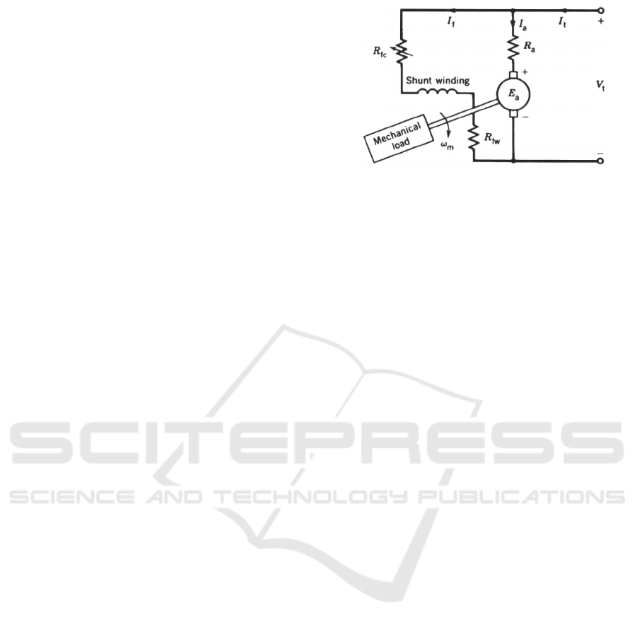
2.2 Direct Current Motor Shunt
The schematic of a shunt winding DC motor is
described by Sen (1987) as shown in Figure 2 in this
motor, the armature circuit and the shunt field circuit
are connected by a DC power supply with a fixed
voltage Vt.
The external field shear resistance (Rtc) is used in
the field circuit to control the motor speed. Since this
motor draws power from the DC power supply, the
motor current flows into the machine from the
positive terminal of the DC power supply.
The motor equation for steady state operation is as
follows:
V
I
R
𝐸
(5)
I
I
I
(6)
E
K
𝜙𝜔
(7)
𝐸
𝑉
𝐼
𝑅
(8)
The armature current (I
a
) and motor speed ꞷ
m
depend on the mechanical load connected to the
motor shaft.
Figure 2: The equivalent circuit of a shunt direct current
motor (Priyambodo et al., 2021).
3 METHODS
This research will be conducted virtually using PSIM
software. Schematic of the design in Figure 1. The
research was carried out with the initial stages of
preparing tools and components that would later be
used to make a controlled three-phase rectifier circuit.
Making a controlled three-phase rectifier circuit
begins with setting and taking the components that
will be used, then pulling the circuit wiring path on
the schematic board, as shown in Figure 1. After that,
the input voltage amplitude setting on each Variac is
set to 110V. After setting up and making the scheme,
the voltmeter and ammeter were installed which aims
to determine the value of voltage and current on the
source side and the load side.
After the circuit is ready, then a test is carried out
by turning on the power supply. During the trial,
sampling of experimental data will be carried out by
recording the values that appear on the voltmeter and
ampere meter measuring instruments to the
experimental results table. This research was
conducted with two types of experiments, namely
experiments with constant loads and experiments
with varying loads. After the experiment is complete,
the power will be turned off.
4 RESULT OF THE STUDY
The specifications of the rectifier made are as
follows:
𝑉
0 100𝑉
(9)
𝑉
3 110𝑉
(10)
𝑉
7,5
𝐴
(11)
Three Phase Controlled Rectifier Circuit for Characteristic Control in DC Shunt Motor
109
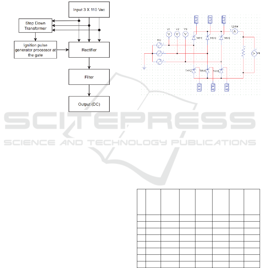
4.1 Block Diagram
This rectifier uses a power transformer which acts as
a three-phase line voltage ballast. This is because a
rectifier circuit that uses a thyristor (SCR) cannot
withstand relatively high unstable voltages. If the
voltage becomes unstable, it may not be possible to
properly control the start time of the thyristor.
Figure 3: Block circuit diagram.
The ignition angle of the rectifier circuit is
regulated by a control circuit which acts as a pulse
angle transmitter (α) in the rectifier power circuit. The
step-down transformer used has a rated current of 1
amp and an output voltage of 15 volts and is used as
a power source for the processor IC pins. This IC acts
as a sine wave sync and produces a sawtooth wave.
The processor, as a form of launch at the gate, uses
the TCA 785 chip, which acts as a gate signal
generator for the thyristor, to operate the thyristor and
generate a DC waveform at the output terminal.
Capacitors and filters are used to form a better DC
filter. With filter capacitors, when the voltage rises,
the capacitor is charged, and when the voltage reaches
zero, the capacitor discharges that charge to the load.
Whereas in an inductor filter, the inductor
accumulates current when the current decreases, and
the inductor discards the stored current when the
current rises.
4.2 Control Circuit
The control circuit consists of the following:
1. The TCA 785 chip processor SCR trigger
control circuit uses the TCA 785 chip processor
to control the ignition angle of the rectifier
circuit to create a DC voltage variable.
2. Pulse Transformer Driver Circuit A pulse
transformer is used as a component to form a
trigger pulse which is supplied to the gate of the
SCR. The trigger pulse is generated from the
square wave signal generated by the switching
transistor. Transistor-based controllers, on the
other hand, emit pulses from the TCA 785 chip
processor.
Figure 4: Control circuit of three-phase controlled rectifier.
4.3 Testing
Figure 4 is the implementation used for the circuit and
will be simulated for discussion. The following is a
table containing test result data, including the
following:
4.3.1 Measurement with Constant Load,
Torque (T) = 0.1 N-M
Table 1: Measurement data with constant load.
No Trigger
Angle
(α)°
Rectifier
Output
Voltage
(Volt)
Field
Current
(mA)
Anchor
Current
(A)
Load
Current
(A)
Torque
(N-m)
Speed
Motor
(RPM)
1 50 210 90 0,24 0,45 0 2600
2 55 200 86 0,24 0,575 0,1 2500
3 65 180 76 0,28 0,65 0,1 2250
4 75 160 68 0,3 0,675 0,1 2050
5 85 140 60 0,32 0,7 0,1 1875
6 95 120 50 0,34 0,725 0,1 1700
7 105 100 42 0,325 0,775 0,1 1500
8 115 80 32 0,32 0,95 0,1 1150
From the above experiment, the greater the delay
angle of the rectifier, the lower the output voltage of
the rectifier which is equal to the motor input voltage.
When the input voltage to the motor decreases, the
iCAST-ES 2022 - International Conference on Applied Science and Technology on Engineering Science
110

motor speed m decreases. It can also be seen that the
field current decreases as the input voltage to the
motor decreases, and the load current increases as the
voltage decreases. Figure 5 shows a graph of the
rectifier output voltage and motor speed as a function
of the discharge angle at torque T = 0.1 N–m
(constant).
Figure 5: Graph of rectifier output voltage and motor speed
as a function of trigger angle.
4.3.2 Measurement with Changing Load
Table 2: Measurement data with changing load.
No Trigger
Angle
(α)°
Rectifier
Output
Voltage
(Volt)
Field
Current
(mA)
Anchor
Current
(A)
Load
Current
(A)
Torque
(N-m)
Speed
Motor
(RPM)
1 85 140
58 0,32 0,4 0 2000
57 0,36 1,15 0,3 1675
56 0,42 1,6 0,45 1500
56 0,54 2,4 0,6 1300
2 105 100
40 0,32 0,42 0 1700
39 0,42 1,55 0,3 1050
38 0,48 1,9 0,35 800
38 0,60 2,5 0,45 500
3 115 80
34 0,37 0,5 0 1500
34 0,35 0,8 0,1 1350
32 0,38 1,4 0,2 900
32 0,42 1,8 0,3 400
Figure 6 shows a graph of the rectifier output voltage
and motor speed as a function of the discharge angle
at torque T = 0 N–m.
From the experimental data above, we can see the
characteristics of the motor, including:
Relationship between velocity ꞷ
m
and armature
current Ia. In this experiment, the magnetic flux is
assumed to be constant, so m is proportional to Ea,
and if the motor rotation is also constant, Ea will be
constant. Ea and magnetic flux decrease with
increasing load. As the load increases, the rotor speed
decreases and the counter electromotive force (Ea)
decreases. The smaller Ea, the greater the ratio of Ea
to Vt (Ea << Vt). Therefore, the armature current (Ia)
drawn from the source by the motor increases.
Lowering Ea affects speed when slowing down. As
the load increases, the speed will decrease.
Figure 6: Graph of rectifier output voltage and motor speed
as a function of trigger angle.
Figure 7: Graph of velocity as a function of armature
current ꞷ
m
= f(Ia), Vt constant.
Figure 8: Graph of torque as a function of armature current,
T = f(Ia), Vt konstan.
When viewed through the relationship between
torque (T) and armature current (Ia), when the
terminal voltage Vt is constant, the magnetic
amplifier current (Im) is also constant, so it is
210
200
180
160
140
120
100
80
2600
2500
2250
2050
1875
1700
1500
1150
0
500
1000
1500
2000
2500
3000
50 55 65 75 85 95 105 115
Voltage (Volt) Revolution per Minute (RPM)
140
100
80
2000
1700
1500
0
500
1000
1500
2000
2500
85 105 115
Voltage (Volt) Revolution per Minute (RPM)
2000
1675
1500
1300
0
500
1000
1500
2000
2500
0,41,151,6 2,4
Revolution per Minute (RPM)
Load Current (A)
0
0,3
0,45
0,6
0
0,2
0,4
0,6
0,4 1,15 1,6 2,4
Torque (N-m)
Load Current (A)
Three Phase Controlled Rectifier Circuit for Characteristic Control in DC Shunt Motor
111

constant. When the terminal voltage is constant, the
torque of the shunt winding motor depends only on
the armature current (Ia). From the torque equation
when T = K.Ia.Φ. Therefore, T depends on the
armature current (Ia). In the above experiment, the
greater the torque, the greater the torque. Torque
characteristics as a function of armature current at
140 volts.
5 CONCLUSIONS
After testing the three-phase controlled rectifier
circuit, conclusions can be drawn, including:
1. In general, the effectiveness of using a thyristor
as the main component of a rectifier using phase
control techniques is very good, but this is
actually a refinement of the trigger pulse
generator control circuit to achieve maximum
performance, depending on the degree. In this
tool, the synchronization of the control signal
processing output with the network input signal
is a very important part because the delay in the
input signal sampling time and trigger pulse
generation for control is increased.
2. In a constant load test, the maximum output
voltage occurs at a trigger angle = 50°, or 210
volts at a motor speed of 2600 rpm. When the
output voltage of the rectifier drops to 80 volts,
the motor speed also drops significantly to 1150
rpm. In this experiment, it was found that as the
delay angle of the rectifier increases, the input
voltage of the motor decreases. When the input
voltage drops, the motor speed m drops.
3. From testing with different loads, at a constant
motor terminal voltage, the motor speed
decreases with increasing load (the torque value
increases). Example: If the motor input voltage
is 140 volts, the motor speed is 2000 rpm and
the torque is 0. Increasing the torque to 0.3 N –
m will decrease the motor speed to 1675 rpm. If
the torque is increased to 0.45Nm, the engine
speed will drop to 1500rpm. Then, when the
torque increases to 0.6 Nm, the engine speed
drops more significantly to 1300 rpm.
4. Adjusting the angle on the thyristor used in this
rectifier can affect the output voltage for the
motor, thus causing a decrease or increase in
RPM. So this controlled rectifier is very suitable
for use when requiring changes in RPM speed
without changing the input voltage value.
REFERENCES
Angga, Anggara Trisna Nugraha, et al. "Solutions For
Growing the Power Factor Prevent A Reactive.
Electricity Tariff And Decrease Warmth On Installation
With Bank Capacitors." Applied Technology and
Computing Science Journal 4.1 (2021): 35-46.
Febrianto, Roby, and Anggara Trisna Nugraha. (2021)
"PERANCANGAN BATTERY CHARGER
MENGGUNAKAN ENERGI PENGGERAK MIKRO
HIDRO BERBASIS ARDUINO UNO." Seminar
MASTER PPNS. Vol. 6. No. 1.
Fitzgerald, A.E., Charles kingsley Jr.,Stephen D. Umans
(1996). Mesinmesin Listrik, Edisi keempat, terjemahan
Djoko Achyanto Msc. EE. Erlangga.
Heraja, B. L (1984), Element Of Electrical and Mechanical
Engineering, Ram, Nagar, New Delhi.
Jacob M. Ph.D, C.C. Halkias, Ph.D (1990), Elektronika
Terpadu, Penerbit Erlangga.
Kenjo, T (1995).,Power Electronics For The Microposesor
Age, United State By Oxford University Press Inc.,
New York.
M Agus Praztyio Elektronika Dasar (2016).
Malvino, Barmawi (1996). PrinsipPrinsip Elektronika,
Edisi Ketiga, Erlangga, Jakarta.
Nugraha, Anggara Trisna, Moch Fadhil Ramadhan, and
Muhammad Jafar Shiddiq.(2022). "DISTRIBUTED
PANEL-BASED FIRE ALARM DESIGN." JEEMECS
(Journal of Electrical Engineering, Mechatronic and
Computer Science) 5.1.
Petruzella, F.D.(2001). Elektronika Industri, Penerbit Audi
Offset, Yogyakarta.
Priyambodo, Dadang, and Anggara Trisna Nugraha.
(2021)"Design and Build A Photovoltaic and Vertical
Savonious Turbine Power Plant as an Alternative
Power Supply to Help Save Energy in Skyscrapers."
Journal of Electronics, Electromedical Engineering,
and Medical Informatics 3.1 (2021): 57-63.
Putra, Muhammad Dwi Hari, and Anggara Trisna
Nugraha.(2021). "RANCANG BANGUN BATTERY
CHARGER DENGAN SISTEM CONSTANT
VOLTAGE BERBASIS KONTROL PI." Seminar
MASTER PPNS. Vol. 6. No. 1. 2021.
Rasyid, M.H. (1999). Elektronika Daya, Edisi bahasa
Indonesia, PT. Prenhallindo, Jakarta.
Realdo, Adam Meredita, Anggara Trisna Nugraha, and
Shubhrojit Misra (2021). "Design and Development of
Electricity Use Management System of Surabaya State
Shipping Polytechnic Based on Decision Tree
Algorithm." Indonesian Journal of Electronics,
Electromedical Engineering, and Medical Informatics
3.4 (2021): 179-184.
iCAST-ES 2022 - International Conference on Applied Science and Technology on Engineering Science
112
