
CAD & CAM Design System of 3D Concrete Printing Machine for
Building
Nandang Rusmana
a
, Heri Setiawan
b
and Muhammad Ghizar Muttaqien Nadhif
Manufacture Engineering Department, Bandung Polytechnic of Manufacturing, Jl. Kanayakan No. 21, Bandung, Indonesia
Keywords: Computer Aided Design (CAD) & Computer Aided Manufacturing (CAM) System, 3D Concrete Printing,
Mach3 CNC Controller, SketchUp, 3D Slicer Ultimaker Cura.
Abstract: CAD & CAM system is a computer-aided software tool that can simplify the process of 3D printing of
buildings, this CAD & CAM serves as a tool that bridges the 3D design of building models with the 3D
printing manufacturing process. Based on the results of the CAD & CAM system design on a 3-dimensional
building concrete casting machine, the system tends to be almost the same as 3D Print FDM in general but is
adjusted to the object to be printed, namely the building. The process of making a 3D CAD design of a
building construction model using the SketchUp 2014 software tool, then the 3D building model is converted
into a G-Code program using the help of the CAM 3D Slicer Ultimaker Cura v3.5.1 software with the machine
parameter approach that is on the 3-dimensional building concrete casting machine. From the results of a
simple trial of inputting the G-Code program generated by 3D Slicer Ultimaker Cura on a computer-based
Human Machine Interface (HMI), namely Mach3. The tool-path generated on Mach3 is in accordance with
that generated from the slicing process by Ultimaker Cura and the G-Code program can also be scanned and
read by Mach3 although further testing is needed to adjust the movement of control components controlled
by Novusun NVUM 6 Axis Mach3 CNC Controller so that the parameters previously set on Ultimaker Cura
can run according to the printing process.
1 INTRODUCTION
Along with the times, the manufacturing industry is
always developing continuously so that advances in
manufacturing technology can simplify and speed up
the manufacturing process, as well as civil technology
that applies Additive Manufacturing technology by
means of 3D Print for building construction.
According to the international standard ISO/ASTM
52900, Additive Manufacturing (AM) is defined as
the process of combining materials to make a certain
part of the 3D model data, which is carried out layer
by layer (Paolini et al, 2019). Thus, the construction
of buildings can be operated by 3D Prints. The
processing time is relatively faster than the
manufacture by human labor.
This 3D Print building or 3-dimensional building
concrete machine (3D Concrete Printing Building)
has a standard function that is very similar to the
standard Fused Deposition Modeling Printer (FDM
a
https://orcid.org/0000-0001-8772-5626
b
https://orcid.org/0000-0001-8767-1429
Printer) (Jay et al, 2019), where the building to be
printed can be formed by adding concrete layer by
layer through a nozzle whose movement is operated
by the program. 3D Print this building requires a
computer programming system that is able to act as a
bridge between the 3D design of the building
construction model and the manufacturing process, so
a CAD & CAM system is needed with computer-
aided software tools that can simplify the 3D printing
process of the building.
CAD is a technology related to the use of
computer systems to assist in the creation and
modification of designs, while CAM is a technology
related to the use of computer systems to plan,
manage, and control manufacturing operations (Lee,
1999). The computer system used is in the form of
software.
The software used in CAD is SketchUp software,
which is one of the popular CAD software used by
architecture that can make it easier to make 3D design
Rusmana, N., Setiawan, H. and Nadhif, M.
CAD & CAM Design System of 3D Concrete Printing Machine for Building.
DOI: 10.5220/0011816700003575
In Proceedings of the 5th International Conference on Applied Science and Technology on Engineer ing Science (iCAST-ES 2022), pages 499-506
ISBN: 978-989-758-619-4; ISSN: 2975-8246
Copyright © 2023 by SCITEPRESS – Science and Technology Publications, Lda. Under CC license (CC BY-NC-ND 4.0)
499
of a building models and in operation it is also lightly
processed by computers. In CAM, the software used
is the 3D Slicer Ultimaker Cura which is generally
used in making FDM 3D Printing processes and its
intuitive interface makes it easy to use.
Thus, this study is intended to explain how the
CAD & CAM system is used in a 3-dimensional
building concrete casting machine (3D Concrete
Printing Building) which in the system explains how
the compatibility of the CAD & CAM software
available with the machine, how to describe the CAD
manufacturing process. & CAM with a parameter
approach on a 3-dimensional building concrete
casting machine, and how the output on the system is
in the form of a G-Code program so that it can be read
by the machine controller.
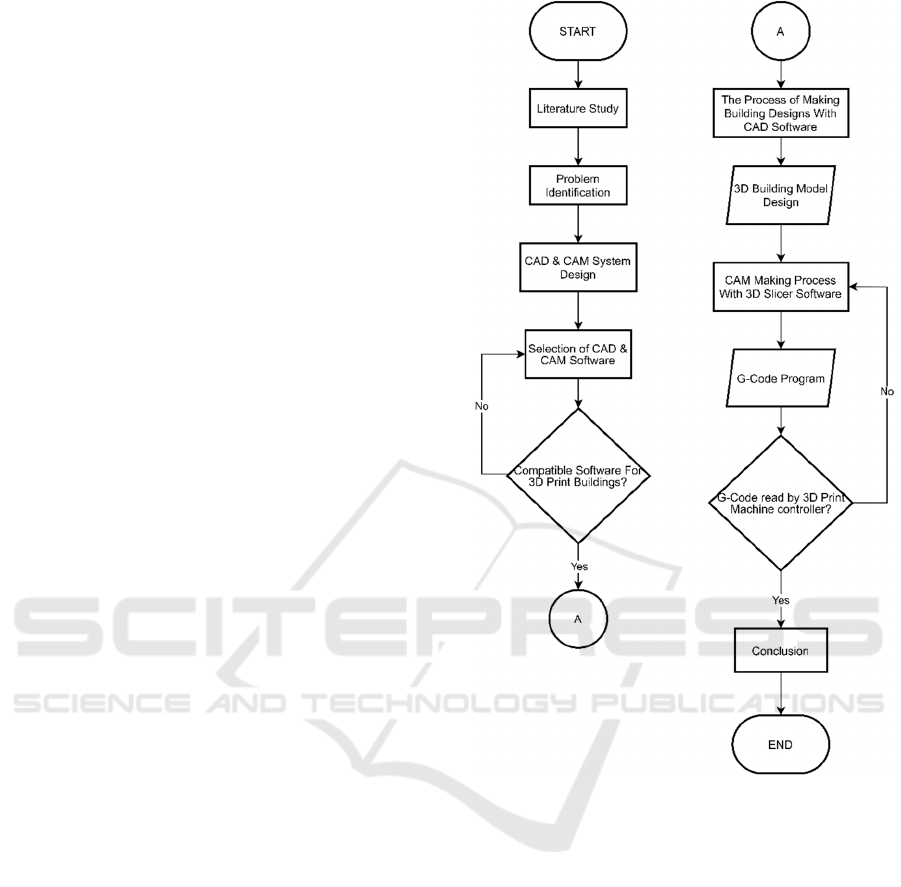
2 METHOD
In this method of completion, it begins by looking for
references regarding the control system for 3D Print
in general and its relation to the CAD & CAM process
in 3D Concrete Printing. From the references
obtained, it turns out that the working principle of 3D
Print is generally the same as 3D Concrete Printing,
it's just that there is a development in the control
system and there are also adjustments to the CAM
process.
The problem was then identified in the CAD &
CAM system, where the CAM software available in
general is for 3D Print Fused Deposition Modeling
while on the 3D Print machine the building uses a
Mach3 CNC Controller so it is necessary to adjust the
machine parameters so that the resulting G-Code can
be read by the controller and works fine.
With the problem identified, the system is then
determined so that CAD & CAM can be suitable for
the building's 3D Print machine. One of the system
designs is made as an illustration of how an activity
or process of a CAD & CAM system will run on a
building 3D Print machine.
This CAD & CAM system is a computer software
so it is necessary to find an alternative to CAD &
CAM that is compatible with the three-dimensional
printing process of the building. The selection of
CAD software used was based on consideration of
features that matched the building construction model
to be printed and for CAM software was chosen based
on the consideration of software compatibility on the
Mach3 controller firmware.
Figure 1: Method Flowchart.
CAD & CAM software needs to be checked first
for compatibility of the software used for 3D Print
buildings. The pre-determined software options are
checked for specifications whether they are suitable
and compatible with the control system to be used.
An overview of the CAD process is explained so
that the system created can describe the process of
making building construction designs with CAD
SketchUp 2014 software. Creating a design process
with building construction that is designed as much
as possible is still within the scope of the building's
3D Print machine capabilities.
The description of the process of making CAM is
also explained, this CAM uses 3D Slicer Ultimaker
Cura software. The process is carried out using a
machine parameter approach in the 3D Slicer
software that is used so that the resulting G-Code
iCAST-ES 2022 - International Conference on Applied Science and Technology on Engineering Science
500

program can be read by the building's 3D Print
machine controller.
The resulting G-Code program needs to be
checked for readability with the Mach3 controller. If
it is not readable, it is necessary to return to the CAM
manufacturing process to analyze the problem. If the
CAM manufacture still gets results that cannot be
read by the controller, it is necessary to re-select the
CAM software used so that it can be compatible with
the machine controller.
3 RESULT AND DISCUSSION
3.1 Design of CAD & CAM System for
Building 3D Printing Machine
The CAD & CAM system on the building 3D Print
machine, was designed based on existing software
tools for most FDM 3D Print machines because there
is no software specifically for the building 3D Print
machine so it is necessary to adjust the machine
parameter approach so that it can be processed by the
building 3D Print machine well.
The output generated by this system will be in the
form of a G-Code program. The program can instruct
the building 3D Print machine control so that the
movement of the nozzle can be in accordance with the
desired 3D printing process based on what has been
set on the CAM.
Figure 2: G-Code Program Input Flow.
Description:
[1 & 2] Z Axis Pillar Slider Motor
[3 & 4] Y Axis Pillar Slider Motor
[5] X Axis Pillar Slider Motor and Nozzle
[6] Human Machine Interface Mach3
The G-Code program is inputted through the HMI.
HMI integrated with the Novusun NVUM 6 Axis
Mach3 CNC Controller will process the G-Code
program and then send signals to control components
such as the motor on the slider and the extruder motor
on the nozzle. The control components are active and
move according to the program instructions on the
controllers.
3.1.1 3D Print Concrete Building CAD
System
The CAD system used in the 3D printing process of
this building uses CAD software tools to facilitate the
3D design process of building models that are usually
used by architecture so that it can facilitate the design
of special building designs that will be printed later.
The default CAD file format saved by CAD software
is usually different, therefore it needs to be converted
to another standard format such as STL or OBJ that is
compatible with the CAM software used.
Figure 3: CAD System Flowchart.
3.1.2 3D Print Concrete Building CAM
System
The CAM system in this building's 3D Print process
includes making special settings for Custom Printers,
Custom Materials, and Custom Profiles. Special
arrangements need to be made because this CAM
software that is available is generally made for 3D
Print FDM, where the extruded material is
thermoplastic so that there are some parameters that
will not be used and some must be added in order to
CAD & CAM Design System of 3D Concrete Printing Machine for Building
501
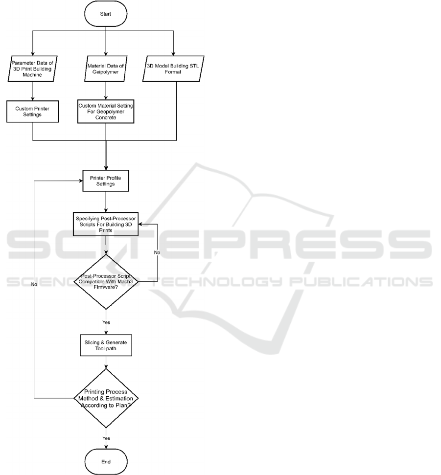
adapt to the building's 3D Print machine. For
example, there is a heating temperature parameter in
the nozzle area to melt thermoplastic filaments, while
printing with this geopolymer material basically does
not require a melting process.
Figure 4: CAM System Flowchart.
This CAM is also programmed to produce
standard 3D Print G-Code, while the controller used
in this 3D Print machine is CNC Mach3. Thus, there
will be a slight difference in the G-Code program read
by the machine controller and cause some G-Code
programs to malfunction or be ignored. Even so, the
program can continue to run until the end. As for the
post-processor script which is needed to facilitate
special work on the building printing process, the
post-processor script itself is programming code that
reads the G-Code generated by the CAM when slicing
the model and modifies it to the desired result before
Cura sends the final result to 3D printers.
3.1.3 Selection of CAD & CAM Software
CAM computer software for the 3D printing process
is generally available only for thermoplastic Fused
Deposition Modeling 3D Printers, so this selection is
necessary so that the CAM software used can be
compatible with the 3D Print machine for the building
to be made. In general, there are many choices of
software in CAD for various engineering fields, as
well as in CAM software so that it needs to be
narrowed back to its application function. 3D Print of
a building is a job whose application is more directed
at the realm of civil engineering because the object it
prints is a building construction, therefore, for the 3D
CAD model design process, CAD software is needed
that is able to support building construction design
work.
3.1.4 CAD Software
SketchUp 2014 was chosen as computer CAD
software for making 3D models of building
construction on a 3D Print machine because it is easy
to use and the computer specifications required are
not too high. But in reality all these CAD software are
the same depending on what they are applied for, the
convenience of the user, and the capabilities of the
computer they are using. So that the choice of CAD
software for a building 3D Print machine can be said
to be relative as long as the most important thing is
that the stored 3D CAD digital design file must be in
STL file format so that it can be compatible with
many 3D print CAM software.
3.1.5 CAM Software
In practice, this CAM serves as a bridge between the
construction of a digital 3D model (which is created
through CAD) and a manufacturing process system
by translating the digital 3D object model into a
program of instructions to be executed by the
machine. However, most of the 3D printing
technology process is not carried out with the term
CAM software but with 3D Slicer software, where the
3D Slicer is not categorized as a CAM in general even
iCAST-ES 2022 - International Conference on Applied Science and Technology on Engineering Science
502
though it performs the same function so that in
subsequent writings will use the term 3D Slicer as a
CAM 3D Print (Grames, 2021). This 3D Slicer
software is compatible with 3D print technology in
general because of the features in it that support
Printer Fused Deposition Modeling (FDM)
parameters, similar to those in 3D Print buildings.
Ultimaker Cura version 3.5.1 was chosen as 3D
Slicer software because, Cura's interface is intuitive
and user-friendly for beginners, but there are more
complete settings if needed so that it can be adapted
to the 3D Print engine building. Compatible with
many 3D Printer machines, especially on firmware
other than 3D Print machines, namely Mach3 CNC
Controller. Compatible with various types of 3D
CAD file formats. There is a custom post-processor
script on Cura that can be used for the construction
process on the overhang of the building. The version
chosen is 3.5.1 because in another version there is a
bug in the G-Code flavor Mach3 so it is not
compatible with 3D Print building controller.
3.2 CAD Process on 3D Printing
Building Machine
The CAD process of the 3D Print building machine is
the creation of a 3D model of building construction
with the help of CAD software. From what has been
determined previously, the CAD software used is
SketchUp. Before entering this process, some
information data is needed in advance about building
construction as an example of the CAD
manufacturing process, including:
1) The available working area is 5 x 4.5 x 3 meters
with an offset of 0.5 meters as a safe distance for
the printhead nozzle with X, Y, and Z pillar
construction. After an offset of 0.5m is made from
the working area the size of the house to be printed
becomes 4m x 3.5m x 2.5m.
2) The 3D model objects created in CAD are
building constructions that will only be printed by
geopolymers, which are mostly walls.
3) The building construction to be printed is a
building in the form of a non-standard house (not
based on the standard type of house in Indonesia)
which only has one floor level because it is limited
by the working area of the building's 3D Print
machine.
4) The house building consists of one main room and
one bathroom.
5) The thickness of the walls of the house is 15 cm.
6) There is one main door, two main windows, and
one bathroom door.
7) With its non-standard type, the building of this
house is more like a premium boarding room with an
attached bathroom which is suitable for the upper
middle class.
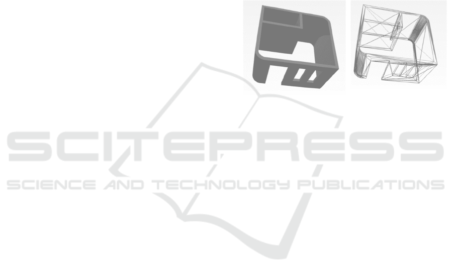
3.3 Export CAD File into STL
CAD files need to be saved or exported into STL files
because they are easy to manipulate in the process
planning system (Zhou, 2005) (CAM), especially in
the slicing process by 3D Slicer Ultimaker Cura
software. without showing color, texture, and other
general attribute models so that it is quite simple to
process in the slicing process.
(a) (b)
Figure 5: (a) 3D CAD Model (b) 3D CAD Model After
Converting to STL.
3.4 CAM Process with Ultimaker
Cura Software
The process of making CAM on the 3D Print building
machine is carried out with the 3D Slicer Ultimaker
Cura software, this process begins with making
special settings for the printer machine, special
settings for materials, special settings for printer
profiles, and in addition to setting post-processor
scripts. Thus, although this Ultimaker Cura 3D Slicer
is not intended for 3D printing with geopolymer
materials, it can be adjusted by making profile
settings that are close to the parameters of the 3D
Print building machine.
3.4.1 Custom Printer Settings on Ultimaker
Cura
This custom printer setting is made in such a way
because Cura defaults machine profile is unavailable
for a building 3D printer, this building 3D Printer
machine is a machine made in the final project at the
Bandung Polytechnic of Manufacturing and is not
commercially available.
Information on building 3D Print engine
parameter data is required, which include:
CAD & CAM Design System of 3D Concrete Printing Machine for Building
503
1) The available working area is 5 x 4.5 x 3 meters
with an offset of 0.5 meters as a safe distance for
the printhead nozzle with X, Y, and Z pillar
construction.
2) The working area is square.
3) The controller uses CNC Mach3, so the G-Code
flavor used is Mach3.
4) It only has one extruder on the nozzle.
5) The height of the gantry or the distance between
the base of the working area and the construction
of the X pillar is assumed from the height of the
working area plus the thickness of the X pillar,
which is about 3m + 0.5m = 3.5m.
6) Because the material to be printed uses a
geopolymer, the compatible filament diameter
material is the same as the nozzle hole diameter.
7) Start and End G-Code are left default.
From the data above, it can be input to the custom
printer machine settings in Settings → Printer → Add
Printer → Custom FFF Printer.
3.4.2 Custom Material Setting for
Geopolymer
Ultimaker cura does not provide material profiles for
types of materials that are cement or mortar such as
geopolymers, so it is necessary to add special settings
in the Material Settings section. Geopolymers have
material properties as shown in the following table:
Table 1: Geopolymer Concrete Material Properties
(Meng et al, 2019).
Properties Geopolymer Concrete
Mass density 2,40 g/cm³
Poisson’s ratio 0.21
Bending strength 10.1 Mpa
Compressive Strength 93.6 Mpa
The material properties for this custom material
setting are only the mass density, so other information
is ignored. For settings, it can be done by selecting
Settings → Extruder 1 → Materials → Manage
Materials.
3.4.3 Custom Printer Profile Settings
Before specifying the custom printer profile settings,
first import or enter the object to be printed by
selecting File → Open File(s) and then selecting the
3D CAD file of the building to be printed in STL or
OBJ form. Then readjust the size and scale of the
object, also adjust the position of the object so that it
loads the working area properly and correctly.
Custom printer profile settings are settings for the
printing process method which can affect the nozzle
movement pattern as well as what instructions are
needed so that the machine can print objects
according to what has been designed. Therefore, the
resulting output will be in the form of a G-Code
program. These settings include:
3.4.4 Layer Height
Determining the layer height can affect the quality of
print detail that will be obtained. The smaller the
height resolution of each layer, the better the surface
detail obtained but the longer the printing process
(Grames, 2021). The layer height in the 3D Print of
the building is assumed to be 1 inch or 25.4mm. The
height is uniform with the hole inside the nozzle
diameter.
3.4.5 Shell
The shell is the outline or the outer boundary of each
layer of the object to be printed (Wobith, 2019). This
shell can affect the stability of the model. In
determining the parameters of this shell, there are
several settings in it, namely the thickness of the shell
wall (wall thickness), the number of layers of the shell
wall (wall line count), and the thickness of the
top/bottom thickness (top/bottom thickness).
In setting the shell for 3D Print printing of
buildings, from many video references on the internet
that most house walls are printed with a shell wall as
thick as a nozzle diameter that is 25.4mm in this case
and there is only one layer of wall so that it will
produce a cavity in the wall of the house which has a
thickness of 15cm. The cavity will later be filled with
infill with a certain pattern and density to strengthen
the building construction.
3.4.6 Infill
The arrangement of this section plays an important
role in influencing the strength and weight of the
building construction to be printed (O’Connel, 2022).
There are two important parameters in the infill
setting, namely the infill density and the infill pattern.
Fill density for standard printing is around 15% -
50% with simple patterns such as Grid patterns, too
dense infill and too complex patterns can cause the
printing process to be very long and increase the
complexity of nozzle movement so it is not
recommended for home wall printing. The infill
density is sufficient at 20% to speed up the printing
process but is still quite sturdy.
iCAST-ES 2022 - International Conference on Applied Science and Technology on Engineering Science
504
3.4.7 Printing Speed and Flow Rate
Printing speed and flow rate can also affect the
quality, accuracy, and even the strength of the
construction to be printed. Too fast causes inaccuracy
of the dimensions of the printed object and can also
reduce the quality of object details.
Printing speed and flow rate for building 3D Print
is in the range of 60 mm/s to 120 mm/s and 37,9 ml/s
to 51,3 ml/s, respectively. The printing speed and
flow rate refers to the research conducted by Daniel
Tay et al. in 2019. Where in this range, the prints tend
not to break and do not experience cracks so that the
prints will be better and stronger. The fastest printing
speed is selected, which is 120 mm/s with flow rate
51,3 ml/s so that the printing process time is shorter.
3.4.8 Travel
Travel is a setting in Cura to control nozzle traffic at
the time of printing. This setting contains several
important parameters, including Combing Mode,
Avoid Printed Parts, Avoid Supports, and Z Hop
When Retracted (Anon, 2022).
Combing Mode functions in reducing the
possibility of defects on the outer surface of the mold
by recalculation of all traveling nozzle movements so
that they remain within the mold limits. Avoid Printed
Parts and Avoid Supports if enabled will make the
printhead avoid parts that are printed while the nozzle
is traveling, assuming the safe distance is one nozzle
diameter which is 25.4mm. While Z Hop When
Retracted allows the printhead to move over the print
without the nozzle touching it, but this parameter is
not really necessary because it will increase the
printing process time.
3.4.9 Post-Processor Script Setup for
Building Printing Process
Post-processing scripts in the 3D Print process of
buildings are needed because they can be used as a
method that can facilitate the installation of manual
support on the overhang section of building
construction. The post-processing script is “Pause At
Height”. The method the script will use is to read all
the G-Code lines, then detect the G-Code at which the
printer will reach the desired height, and add a pause
G-Code, such as the M0 (Unconditional Stop)
command.
To install the Post-processing script this plugin
can be done by selecting Extensions → Post
Processing → Modify G-Code → Add a script →
Pause at height. After that, the Post Processing Plugin
window will appear and the parameter fields that
must be filled in.
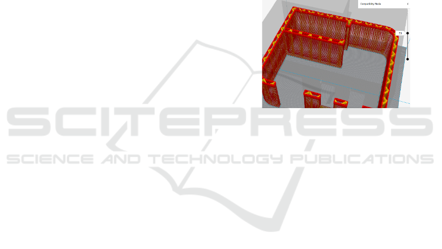
3.4.10 Slicing on Building Objects to Be
Printed
The object that is ready will then be sliced into several
layers, after which the tool-path line and its layers
will appear, so you can see if the nozzle movement
path is in accordance with what was planned.
The display in Figure 4 is an overview of the tool-
path on layer 52 out of a total of 100 layers. You can
see the red lines that show the nozzle movement path
in the formation of the shell wall and the yellow lines
that show the nozzle movement path in the formation
of the filling.
Figure 6: Layer View and Slicing Tool-path Pattern.
3.5 Simple Testing of G-Code
Program on Mach3
This simple test simply checks the G-Code program
whether it can be read by Mach3 and the resulting
tool-path is exactly the same as that produced by
Cura's Ultimaker CAM 3D Slicer. The G-Code
program is inputted through a computer-based
Human Machine Interface (HMI), namely Mach3.
After that Mach3 will scan the loaded G-Code
program before it can be executed.
When the scan is complete, Mach3 will display
tool-path lines on the Display indicating that the next
G-Code program can be executed. However, if after
scanning there are no tool-path lines on the Display,
it means that an error has occurred in the G-Code
program.
G-Code programs that do not experience errors
after being scanned can be seen for their detailed tool-
paths in the Display section, so that it can be easily
checked whether the tool-paths represent the G-Code
programs that have been loaded.
The tool-paths previously generated from the
CAM 3D Slicer Ultimaker Cura process with Tool-
paths displayed on Display Mach3 have similarities,
CAD & CAM Design System of 3D Concrete Printing Machine for Building
505

(A) (B)
Figure 7: Tool-path view (A) Top and (B) Isometric.
but there are limitations to the Display Mach3 feature
which cannot display tool-paths in more detail. Even
so, the G-Code program can still be read by Mach3,
it just needs further testing to adjust the movement of
the control components controlled by Mach3 so that
the previous parameters set on the CAM 3D Slicer
can run according to the printing process.
It is proven that Ultimaker Cura 3D Slicer
software is compatible with Mach3 CNC controllers,
so that the software can be used in a 3D Print
approach to the 3D printing process.
4 CONCLUSIONS
The CAD & CAM system on the building 3D Print
machine is almost the same as the FDM 3D Print in
general. The process of making a 3D CAD design of
a building construction model using the SketchUp
software tool, then the 3D building model is
converted into a G-Code program using the help of
the CAM 3D Slicer Ultimaker Cura software with a
3D Print machine parameter approach of the building.
SketchUp software compatibility meets STL and
OBJ standard file storage, while Ultimaker Cura 3D
Slicer software can be compatible with Mach3 CNC
controllers on building 3D Print machines.
The CAD process in the 3D Print of the building
begins with the creation of a 3D design of the building
construction model and the process of exporting the
file into STL type format with SketchUp software.
The CAM process in the 3D concrete printing
building process consists of making custom settings
for custom printers, custom materials, and custom
printer profiles.
The G-Code program generated by 3D Slicer
Ultimaker Cura can be read by Mach3 CNC
controller.
If using open-source software such as Ultimaker
Cura, pay attention to the updated version. In some
versions there are bugs in the Mach3 firmware that
have not been fixed by the software developer so that
the resulting G-Code program is not compatible.
Overall, using this software produces
performance for 3D building concrete casting with
good execution speed.
REFERENCES
Paolini, A et al (2019). Additive manufacturing in
construction: A review on processes, applications, and
digital planning methods, Additive Manufacturing, 30.
2.
Jay G, S et al (2019). 3D Concrete Printing for
Construction Applications, 3D Concrete Printing
Technology. 4.
Lee, K. (1999) Principles of CAD/CAM/CAE Systems,
Boston: Addison Wesley Publishing Co.
Carolo, L. (2020). What Is a 3D Slicer? – Simply Explained.
From https://all3dp.com/2/what-is-a-3d-slicer-simply-
explained. (Accessed 2022-05-23).
M.Y.Zhou. (2005). STEP-based approach for direct slicing
of CAD models for layered manufacturing,
International journal of production research, 43(15), pp.
3273-3285.
Meng, Q et al (2019). Experimental and numerical
investigation of blast resistant capacity of high
performace geoplymer concrete panels, Composites
Part B: Engineering, 171. 5.
Grames, E. (2021). 3D Printing Layer Height: How Much
Does It Matter?. From https://all3dp.com/2/3d-printer-
layer-height-how-much-does-it-matter. (Accessed 20
22-06-25).
Wobith, E. (2019). 3D Printing Shells – All You Need to
Know. From https://all3dp.com/2/3d-printing-shells-
all-you-need-to-know/. (Accessed 2022-06-24).
O’Connel, J. (2022). 3D Printing Infill: The Basics Simply
Explained. From https://all3dp.com/2/infill-3d-
printing-what-it-means-and-how-to-use-it/ (Accessed
2022-06-26).
Daniel Tay, Y.W et al (2019). Effect of printing parameters
in 3D concrete printing: printing region and support
structures, Materials Processing Technology, 271. 14-
16.
Anon. (2022). Travel Settings. From https://support.
ultimaker.com/hc/en-us/articles/360012611299-Travel
-settings. (Accessed 2022-06-26).
iCAST-ES 2022 - International Conference on Applied Science and Technology on Engineering Science
506
