
Numerical Investigation of a High-Capacity Vertical Submersible
Two-Stage Pump and Realization of an Experimental Test Bench for
Determining the Strains and the Stresses on a Pump Shaft
Patrick Zito Malonda and Guyh Dituba Ngoma
University of Quebec in Abitibi-Témiscamingue, School of Engineering 445,
Boulevard de l’Université, Rouyn-Noranda, Quebec, J9X 5E4, Canada
Keywords: Vertical Submersible Pump, Axial and Radial Forces, Strain, Stress, CFX.
Abstract: A vertical submersible two-stage pump is investigated in terms of the axial and the radial forces on its shaft
due to the liquid flow through the pump while accounting for the different flow rates. Also, a preliminary
experimental test bench is performed to achieve the strains and the stresses on a pump shaft supporting an
impeller as a function of the rotating speed. In fact, from an existing vertical submersible two-stage pump, a
pump model is developed. The continuity and the Navier-Stokes equations are applied to obtain by means of
the ANSYS-codes the fields of the liquid flow velocity and the pressure, as well as the axial and the radial
forces acting on the pump shaft. The numerical results obtained for the pump head are validated using the
experimental results. Three available axial forces for three flow rates from industry are used for the
comparison with the numerical axial forces. The achieved experimental results from the preliminary test bench
reveal that the strains and the stresses on the pump shaft increase with the raising of the rotating speed.
1 INTRODUCTION
The high-capacity submersible pumps are used
extensively in numerous industrial, mining
applications and in the mining sites in construction
for the dewatering and the control of the water level.
The working of these pumps implies a strong
mechanical load on the shaft and its bearings. Thus,
the design process is a big challenge due to the pump
performances to reach. The knowledge of all essential
parameters of the components of the pump as the
diameter, the width of the blades, the angles of the
blades, the thickness of the blades of the impeller and
the diffusers is primordial to assure an optimal
manufacture of pumps (Mbock Singock, 2018).
Indeed, the relative complexity to the analysis of the
fluid flows through the submersible pump leads to the
use of the numerical tools in the goal to determine the
performances of pump notably the head, the brake
horsepower and the efficiency, but also forces applied
on the shaft for a good dimensionality of the bearings.
This is how in the setting of this research, as long-
term goals, it is about developing reliable and precise
numerical approaches to determine the axial and
radial forces, the strains and the stresses on the pump
shaft. The use of these approaches in the design of the
submersible pumps permits to improve the
performances of these pumps more while increasing
reliability and the life span of the plain bearings
and/or antifriction bearings of the pump shaft
(FLYGT, 2004). Moreover, the literature review
related to this research is stated as follows:
a) Axial and radial loads in the centrifugal pumps
and the submersible pumps.
The pump manufacturers are confronted to
problems of unbalance of the axial and the radial
loads on the impeller because of the distribution of
the static pressure on the impeller shrouds. In the case
of a submersible pump, the radial force doesn't
modify the good working of the pump appreciably
whereas the axial force influences considerably on the
working of the pump (Takacs, 2017). The use of an
axial thrust bearing is ideal for the balancing of the
axial force in the single-stage pumps and at low
rotating speeds. Of the methods as balancing holes
and the radial blades can be used to reduce force
acting on the impeller rear shroud (Smith, 2005; Wilk,
2009; Dong, 2018). In the multi-stage pumps,
considering the complexity of the calculation of the
axial force from the distribution of the pressure on the
Malonda, P. and Ngoma, G.
Numerical Investigation of a High-Capacity Vertical Submersible Two-Stage Pump and Realization of an Experimental Test Bench for Determining the Strains and the Stresses on a Pump
Shaft.
DOI: 10.5220/0012127300003546
In Proceedings of the 13th International Conference on Simulation and Modeling Methodologies, Technologies and Applications (SIMULTECH 2023), pages 393-400
ISBN: 978-989-758-668-2; ISSN: 2184-2841
Copyright
c
2023 by SCITEPRESS – Science and Technology Publications, Lda. Under CC license (CC BY-NC-ND 4.0)
393

impeller, the dimensionality of the device of
balancing of the axial force and the thrust bearing is
often defined on the basis of the values by force
measured at the time of the tests of the pump
(Termomeccanica Pompe, 2003). The design of the
volute has an influence on the radial force. This last
is minimal to the point of working of the pump for a
volute of simple design. The inverse occurs for a
circular volute with a maximal force to the point of
good working whereas a volute to double partition
generates an appreciably uniform force (Badr et al.,
2015).
b) Strains and stresses in the centrifugal pumps
and the submersible pumps.
In practice, the regions of stress concentration are
caused by grooves, keyways and cracks that entail an
increase of the stresses in the pieces. At the time of
the pump operating, the impellers in rotation transmit
the mechanical work of the driving machine to the
fluid. So the pressure load of the fluid and the inertia
load due to the rotating speed induce some stresses on
these impellers. The fluid pressure introduces a stress
and a maximal strain more important than the one due
to the inertia force. But with the increase of the
thickness of the blades, the stress and the maximal
strain caused by the load of the inertia force grow
progressively, while the one of the load of the fluid
pressure decreases (Wang et al., 2014). It agrees to
underline that the raise of the diameter of the impeller
also increases the stress and the strain in a centrifugal
pump (Matlakala et al., 2019).
c) Plain bearings and antifriction bearings in the
centrifugal pumps and the submersible pumps.
The adequate choice of the bearings depends on
the dynamic behavior of the shaft, of the rotating
speed and the factors as the bearing positions and the
pump applications (Termomeccanica Pompe, 2003;
FLYGT, 2004; Bolade et al., 2015). During the pump
operating; the bearings take in charge the axial
displacement and the lateral deviation of the shaft.
The capacity of the bearing to function correctly is
damaged by wear, fatigue or the deterioration of the
lubricant. The penetration of particles in a bearing
also entails the elevated stresses and a premature
rupture by fatigue. These particles also produce a
wear reducing the life span of the bearing (FLYGT,
2004). In a centrifugal pump, a thrust bearing must be
used to balance the axial force completely in all
working conditions (Badr et al., 2015).
2 MODEL DESCRIPTION
The model of the vertical submersible two-stage
pump considered in this research is illustrated in
Figure 1 by the solid and the fluid models. It is
composed, inter alia, of a shaft, two impellers, two
diffusers and a volute.
a) Solid model b) Fluid model
Figure 1: Vertical submersible two-stage pump.
3 MATHEMATICAL
FORMULATION
To determinate the field of the liquid flow velocity,
the field of the pressure, the stress and the strain in
a
vertical submersible two-stage pump
, the following
hypotheses are considered for the liquid flow (
La
Roche-Carrier et al., 2013; Malonda et al., 2023),
and
the solid mechanics (
Popov, 1999)
: (a) a steady
state, three-dimensional and turbulence flow using
the k-
model is assumed; (b) the liquid is an
incompressible liquid; (c) it is a Newtonian liquid;
and (d) the liquid’s thermophysical properties are
constant with the temperature; (e) the material is
considered continuous, doesn't have cracks, nor
cavities; (f) the material is homogeneous and
presents the same properties in all points; (g) the
material is considered as isotropic; and (h) no
internal force acts in the material before the
application of the external loads.
3.1 Liquid Flow Velocity and Pressure
The equations of the continuity and the Navier-Stokes
are used to obtain the fields of liquid flow velocity
and pressure. These equations are solved by means of
the ANSYS CFX-code (
ANSYS inc.). The equation of
the continuity is expressed as follows:
0
z
w
y
v
x
u
(1)
SIMULTECH 2023 - 13th International Conference on Simulation and Modeling Methodologies, Technologies and Applications
394

where u(x,y,z), v(x,y,z) and w(x,y,z) are the
components of the liquid flow velocity U(u,v,w).
Accounting for the gravity, the equations of the
Navier-Stokes can be formulated by:
222
222
2
222
222
( 2 )
eff
z
xz x
eff
uu u uuu
uvw
xy z
xyz
p
rvg
x
vv v vvv
uvw
xy z
xyz
2
222
222
( 2 )
z
yz y
eff
z
p
rug
y
ww w www
uvw
xy z
xyz
p
g
z
(2)
where g (g
x
,g
y
,g
z
) ist the gravity acceleration, p is the
pressure; is the density;
eff
is the effective viscosity
accounting for turbulence, it is defined as
.
eff t
is the dynamic viscosity and
t
is the turbulence
viscosity. It is linked to turbulence kinetic energy k
and dissipation ε
(
La Roche-Carrier et al., 2013).
3.2
Axial and Radial Forces
The axial and the radial forces on the impellers are
determined using the ANSYS CFX-code (ANSYS
inc.
). These forces are illustrated in Figure 2 for a
vertical submersible two-stage pump.
Figure 2: Axial and radial force in a model of the vertical
submersible two-stage pump.
3.3 Strains and Stresses
The normal and the shear
stresses on the pump shaft
are determined by means of the equilibrium equations
of elasticity in terms of stress
n
eglecting the forces
per unit of volume
(
Popov, 1999
)
. These equations
are given by:
0
0
0
yx
xzx
xy y zy
yz
xz
z
xyz
xyz
xyz
(3)
The normal and the shear strains are formulated as
follows using the displacements (u,v,w) respectively
in the directions of x, y and z
; ;
; ;
xyz
xy yz zx
uvw
xzz
uv wv uw
y
xyzzx
(4)
The relationships between the stresses and the
strains is given by:
1
()
1
()
1
()
; ;
xxyz
yyzx
zzxy
xy yz
zx
xy yz zx
E
E
E
GGG
(5)
where E is the modulus of elasticity, G is the shear
modulus and is the Poisson’s ratio.
The stresses can be written as a function of the
strains by:
(1 ) ( )
(1 )(1 2 )
(1 ) ( )
(1 )(1 2 )
(1 ) ( )
(1 )(1 2 )
; ;
xxyz
yyzx
zzxy
xy xy yz yz zx zx
E
E
E
GGG
(6)
The stress of von Mises selected for the yield
criteria can be expressed by:
222
12 23 31
1
2
(7)
where
1
,
2
and
3
, are the principal stresses in the
directions of 1, 2 and 3 according to
1
>
2
>
3
(Popov, 1999; Malonda et al., 2023).
3.4 Diffuser Equations
The diffuser equations (Gülich, J. F., 2010; Malonda
et al., 2023) are applied in this research to calculate
the main parameter of the diffusers of the vertical
submersible two-stage pump.
4 NUMERICAL
IMPLEMENTATION,
SUBMERSIBLE PUMP
MODELING AND
SIMULATION STEPS
The differential equations of continuity and Navier-
Stokes from the mathematical formulation including
the model of turbulence are solved using the ANSYS-
CFX module. In sum, Figure 3 illustrates the
Numerical Investigation of a High-Capacity Vertical Submersible Two-Stage Pump and Realization of an Experimental Test Bench for
Determining the Strains and the Stresses on a Pump Shaft
395
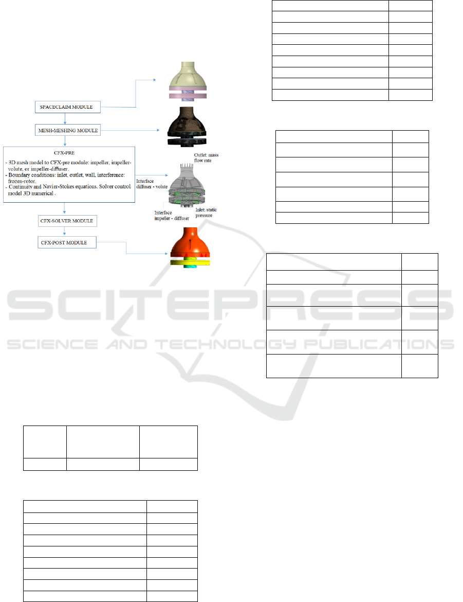
modeling and the simulation steps for a vertical
submersible two-stage pump using the Inventor and
the ANSYS softwares (modules: Spaceclaim, CFX-
Pre, CFX-Solver and CFX-Post) and accounting for -
+++the boundary conditions. The frozen-rotor is used
to take into account the rotating impeller.
Figure 3: Modeling of the reference vertical submersible
two-stage pump et simulation steps.
5 RESULTS AND DISCUSSION
The numerical simulations are done applying the
reference data for the water, the pump shaft, the
impeller, and the diffuser according to the Tables 1-
5.
Table 1: Properties of water in 25 °C.
Density
[kg/m
3
]
Thermal
expansion
coefficient [
K
-1
]
Kinematic
viscosity
[m
2
/s]
997 2,57x10
-1
0,884x10
-6
Table 2: Properties of the 17-4PH steel for the shaft.
Module of the Young [Pa] 1,96x10
11
Poisson ratio 0,3
Compressibility module [Pa] 1,63x10
11
Shear module [Pa] 7,53x10
10
Resistance coefficient [Pa] 9,2x10
8
Ductilit
y
coefficient [Pa] 10
9
Yield stren
g
th [Pa] 7.93x10
8
Ultimate tensile strength [Pa] 1.103x10
9
Density [kg/m
3
] 7750,4
Table 3: Impeller data.
Inlet blade hei
g
ht b
1
[mm] 30.17
Outlet blade hei
g
ht b
2
[mm] 14.48
Hub diameter D
h1
[mm] 44,45
Inlet diameter D
h2
[mm] 107.95
Outlet diameter D
2
[mm] 241
Inlet blade angle β
b1
[°] 16
Outlet blade an
g
le
β
b2
[°] 27.5
Blade thickness e [mm] 3.17
Blade number Z
b
7
Table 4: Diffuser (front side) data.
Inlet blade height b
3
[mm] 17.46
Outlet blade height b
4
[mm] 40.64
Inlet diameter D
3
[mm] 243,84
Outlet diameter D
4
[mm] 311.15
Inlet blade angle α
3b
[°] 10
Blade thickness e
3
[mm] 3.175
Blade numbe
r
Z
Le
8
Table 5: Diffuser (rear side) data.
Return vane number Z
R
6
Outlet return vane height b
5
[mm] 24,4
Diameter at the inlet of the return
vane D
3
[mm]
311,15
Blade angle at the inlet of the
return vane α
5
[°]
95
Blade angle at the outlet of the
return vane α
6
[°]
18
Blade thickness of the return vane
e
3
[mm]
6,04
Moreover, four case studies are accomplished: a)
the characterization and the validation of the
developed vertical submersible two-stage pump; b)
the effect of the axial and the radial loads as a function
of the flow rate; c) the result comparison in terms of
the axial forces; d) the variation of the strain and the
stress on the pump shaft as a function of the rotating
speed.
The numerical simulation results presented in this
research are obtained with the highest accuracy by
conducting mesh-independent solution tests in each
case study using different numbers of mesh elements.
5.1 Numerical Characterization and
Validation of the Model Vertical
Submersible Two-Stage Pump
To numerical characterize the developed pump model
in terms of pump head using the water flow, the flow
SIMULTECH 2023 - 13th International Conference on Simulation and Modeling Methodologies, Technologies and Applications
396
rate range from 492.192 m³/h to 533.196 m³/h are
selected keeping the other parameters constant.
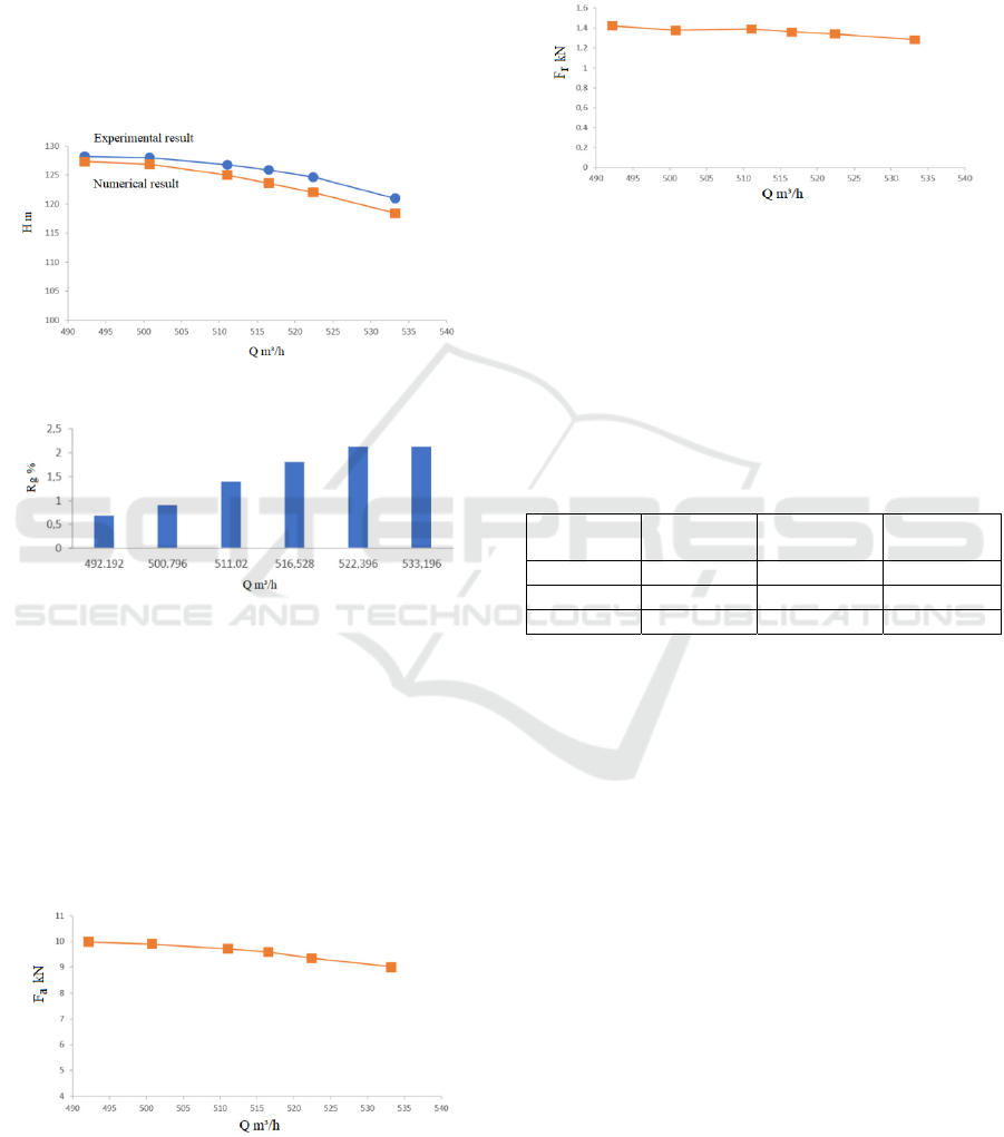
Figure 4 represents the numerical curve and the
experimental curve of pump head as a function of the
flow rate. It is observed a good agreement between
both curves. The corresponding relative deviations in
absolute value of the comparison results as a function
of the flow rate are illustrated in Figure 5. It can be
seen that the relative gaps (R
g
) are lower than 5% for
the considered flow rates. Thus, the pump model can
predict the hydraulic performances of the pump.
Figure 4: Pump head versus flow rate.
Figure 5: Relative gap of the pump head versus flow rate.
5.2 Effect of the Flow Rate on the Axial
and the Radial Forces
The analysis of the stresses and the strains is achieved
by means of the solid model while integrating the
internal pressures of the impellers, the axial and the
radial forces and the torques obtained from the
simulations of the fluid model according to the flow
rate and the rotating speed of the pump.
Figure 6: Axial force versus flow rate.
Figures 6 and 7 illustrate the axial and the radial
forces according to the conditions of working in terms
of flow rate and rotating speed. In these figures, it is
observed that the axial and the radial forces on the
impellers decreases slightly when the flow rate
increases.
Figure 7: Radial force versus flow rate.
5.3 Axial Force Validation for Three
Flow Rates
The comparison between the only three axial forces
obtained from the pump manufacturer corresponding
to three flow rates and the numerical results is
indicated in Table 6 including the relative gaps.
Table 6: Axial forces for three flow rates.
Flow rate
[m³/h]
Numerical
result [N]
Industrial
result [N]
Relative
g
a
p
[%]
114 10115.28 9388 7.1
511 9758.65 9277 4.9
681 7915.51 7581 4.2
5.4 Experimental Results
5.4.1 Test Bench
The developed experimental test bench is preliminary
for obtaining the strains and the stresses on the pump
shaft. It is composed of an impeller, a shaft, two
bearings and an electric motor. Table 7 shows the
main elements of the test bench (School of
Engineering). It is to highlight that this research will
be completed (future work) designing an
experimental test bench for the strain, the stress, the
axial and radial forces using an existing submersible
vertical two-stage pump in operating.
Furthermore, the different steps to achieve the
installation of the Wiser 1 data acquisition system on
the shaft are the following (Figures 8 and 9):
Step 1 (E1): To install the strain gauges on the
shaft and the wire in a complete bridge. As the
maximal concentration zone is on the impeller
keyway, the strain gauges will be placed near of
this zone.
Numerical Investigation of a High-Capacity Vertical Submersible Two-Stage Pump and Realization of an Experimental Test Bench for
Determining the Strains and the Stresses on a Pump Shaft
397
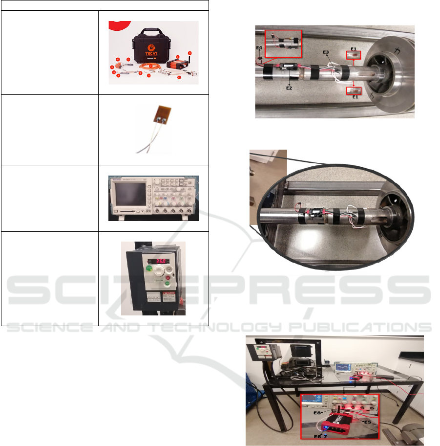
Table 7: Test bench elements.
Element
Tecat (Wiser 1) data
acquisition system
CC-33Ax5 strain gauge
TPS 2024 oscilloscope
Tektronix
ATV312 Variable speed
drive
Step 2 (E2): To bring up the remote transmitter
and the battery, close to the strain gauges.
Step 3 (E3): To use the cable to strain gauges
included to connect the remote transmitter unit in
the circuit of the bridge to strain gauges.
Step 4 (E4): To use the included battery cable to
connect the battery to the remote transmitter unit.
Step 5 (E5): To connect the antenna included to
the basis receiver and the unit supply of the basis
receiver in 12-24V DC via a jack plug connector
or 5V via a micro-USB connector.
Step 6 (E6): If the basis receiver is within reach
of the distant system and that this last is supplied
by a battery, the unit of basis will establish a RF
connection within 10 seconds about.
Step 7 (E7): Once the established cordless
connection, the blue LED placed in the front of
the basis unit must become blue stationary. If it
is the case, the basis unit actively gives out the
signals that it received from the remote control
on the four analog 0-5V output channels.
Step 8 (E8): The analog 0-5V output of the stress
signal must be connected to a data acquirement
system to record the signal of tension.
a)
b)
Figure 8: Installation of the Wiser 1 data acquisition system
on the pump shaft supporting impeller.
Figure 9: Connecting the transceiver of the Wiser 1 data
acquisition system.
5.4.2 Effect of the Rotating Speed on the
Strain and the Stress
Figures 10 and 11 illustrate the strain () and the stress
() on the shaft according to the rotating speed with
the strain gauges placed as indicated on Figure 8.
It can be seen than the strain and the stress increase
with the augmentation of the rotating speed increases.
SIMULTECH 2023 - 13th International Conference on Simulation and Modeling Methodologies, Technologies and Applications
398
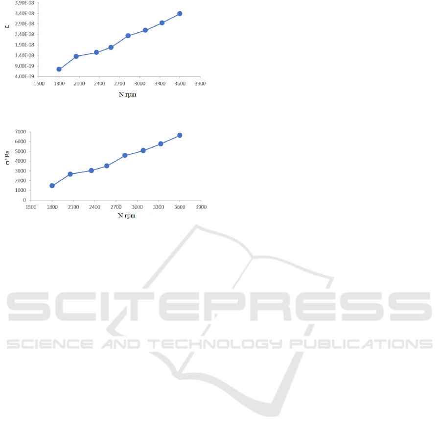
Figure 10: Strain versus rotating speed.
Figure 11: Stress versus rotating speed.
6 CONCLUSIONS
In this study, a submersible vertical two-stage pump
is numerically investigated in terms of the induced
axial and radial forces, and a preliminary test bench
was realized for determining the strains and the
stresses on a pump shaft with an impeller. From an
existing vertical submersible two-stage pump, a
numerical pump model is developed. The ANSYS-
CFX is used for the resolution of the continuity and
the Navier-Stokes equations and the simulations. A
good agreement is achieved between the numerical
simulation results obtained and the experimental
results for the pump head. Furthermore, the numerical
results of the axial force were compared with the
industrial results for three different flow rates. The
relative gaps from both result comparisons reveal the
relevant of the developed model of the submersible
vertical two-stage pump. In addition, an experimental
study is done on a pump shaft. It is observed that more
the rotating speed increases, more the strain and the
stress on the shaft also raise. Further research work is
planned to complete the experimental test bench for
the strain, the stress, the axial and radial forces using
an existing submersible vertical two-stage pump in
operating. This will allow to develop a generalized
numerical correlation for the calculations of the
strain, the stress, the axial and the radial forces in the
submersible vertical two-stage pumps while being
based on the experimental results.
ACKNOWLEDGEMENTS
The authors are grateful to the Technosub Inc.,
Industrial pumps manufacturing and distribution
(Rouyn-Noranda, Quebec, Canada) and the
Turbomachinery
laboratory of the Engineering School
(University of University of Quebec in Abitibi-
Témiscamingue).
REFERENCES
Abdelouahab, M. A., Dituba Ngoma. G., Erchiqui, F.,
Kabeya, P. (2020). Numerical Study of the Axial and
Radial Forces, the Stresses and the Strains in a High
Pressure Multistage Centrifugal Pump.
10th
International Conference on Simulation and Modeling
Methodologies, Technologies and Applications
(SIMULTECH).
ANSYS inc., www.ansys.com.
Badr, H. M., Ahmed, W. H. (2015).
Pumping machinery
theory and practice
. John Wiley & Sons.
Bolade P. S., Madki, S. J. (2015). Analysis of Hydraulic
Thrusts in Centrifugal Pump to Increase the Bearing
Life.
International Journal of Engineering Research &
Technology (IJERT), Vol. 4 Issue 08.
Dong W., Chu W. L. (2018). Numerical Investigation of the
Fluid Flow Characteristics in the Hub Plate Crown of a
Centrifugal Pump.
Chinese Journal of Mechanical
Engineering
, vol. 31, p. 64.
FLYGT, ITT (2004). Industries Engineered for life: Shaft
and Bearings Calculations.
02.03.Eng. 0,5 M. 04.04;
892932; www.flygt.com
.
Gülich, J. F. (2010).
Centrifugal Pumps, second Edition,
Springer.
La Roche-Carrier N., Dituba Ngoma G., and Ghie W.
(2013). Numerical investigation of a first stage of a
multistage centrifugal pump: impeller, diffuser with
return vanes, and casing. ISRN Mechanical
Engineering, Vol. 2013, Article ID 578072, 15 pages.
Malonda, P. Z., Dituba Ngoma, G., Ghié, W., Erchiqui, F.,
Kabeya, P., Kifumbi, F. (2023).
Performance Study of
Vertical Submersible Pump in Terms of Induced Loads
and Vibrations. Lecture Notes in Networks and
Systems, vol 601. Springer.
Matlakala, M., Kallon, D., Mogapi, K., Mabelane I.,
Makgopa, D. (2019). Influence of Impeller Diameter on
the Performance of Centrifugal pumps
. IOP Conference
Series
: Materials Science and Engineering.
Mbock Singock, T. A. (2018). Conception et caractérisation
numérique d'une pompe à turbine verticale de grande
capacité. Université du Québec en Abitibi-
Témiscamingue.
Popov E. P. (1999).
Engineering Mechanics of Solids, 2nd
edition
, Prentice Hall.
School of Engineering, Turbomachinery laboratory (E-
216), University of Quebec in Abitibi-Témiscamingue
(UQAT), www.uqat.ca.
Numerical Investigation of a High-Capacity Vertical Submersible Two-Stage Pump and Realization of an Experimental Test Bench for
Determining the Strains and the Stresses on a Pump Shaft
399

Smith, D. R., Price, S. (2005). Upthrust problems on
multistage vertical turbine pumps.
Proceedings of the
22
nd
International Pump Users Symposium.
Takacs, G. (2017).
Electrical submersible pumps manual:
design, operations, and maintenance
. Gulf professional
publishing.
Termomeccanica Pompe TM.P. S.p.A. (2003).
TERMOMECCANICA Centrifugal pump handbook, La
Spezia - Italy.
Wang, C., Shi, W., Si, Q., Zhou, L. (2014). Numerical
calculation and finite element calculation on impeller of
stainless steel multistage centrifugal pump.
Journal of
Vibroengineering
, vol. 16, pp. 1723-1734.
Wilk, A. (2009), Laboratory investigations and theoretical
analysis of axial thrust problem in high rotational speed
pumps.
WSEAS Trans. Fluid Mech, vol. 4.
SIMULTECH 2023 - 13th International Conference on Simulation and Modeling Methodologies, Technologies and Applications
400
